
Aerospace & Airfield Lighting Glass Design and Manufacturing Guide
Explore the 10 topic guides
Go directly to the application, engineering task, reliability question, or sourcing stage that matches your project.
How the optic connects to system performance
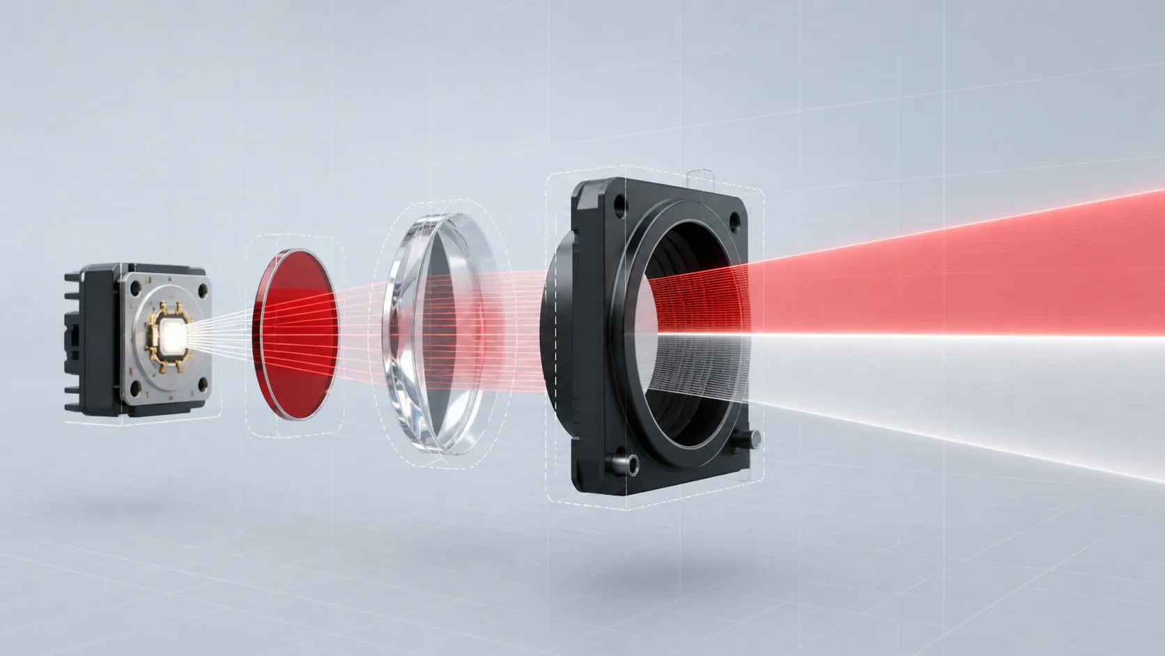
Two relationships prevent many specification errors: the source, filter, lens and mounting datums work as one optical chain; and the finished glass component is only one controlled part of the complete lighting assembly.
Fundamentals of Aerospace and Airfield Lighting Glass
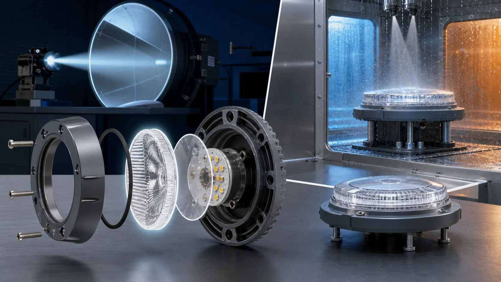
Aviation glass often looks like a passive cover, yet it can shape the beam, change the apparent color, protect a seal, and determine whether a lamp or sensor remains usable after years outdoors. This chapter explains what these components actually do and why two parts that look alike may behave very differently once optical geometry, mounting, temperature, and maintenance are taken into account.
What is aviation lighting glass?
Aviation lighting glass means optical or protective glass used in airport visual aids and aircraft lighting systems. Typical components include runway-light prisms, elevated-light globes, PAPI lenses and filters, aircraft position-light covers, landing-light windows, colored filters, diffusers, and protective covers.
The term describes an application category, not one glass chemistry. A part may seal and protect the light path, or it may directly control beam direction, luminous intensity, chromaticity, spectral transmission, diffusion, and glare. Suitability depends on the finished geometry, mounting, light source, environment, inspection plan, and complete fixture configuration.
Cockpit display covers, camera windows, sensor windows, and other non-lighting transparent components are treated separately in the Cockpit Display Glass & Aerospace Optical Windows guide.
How is aviation lighting glass different from ordinary lighting glass?
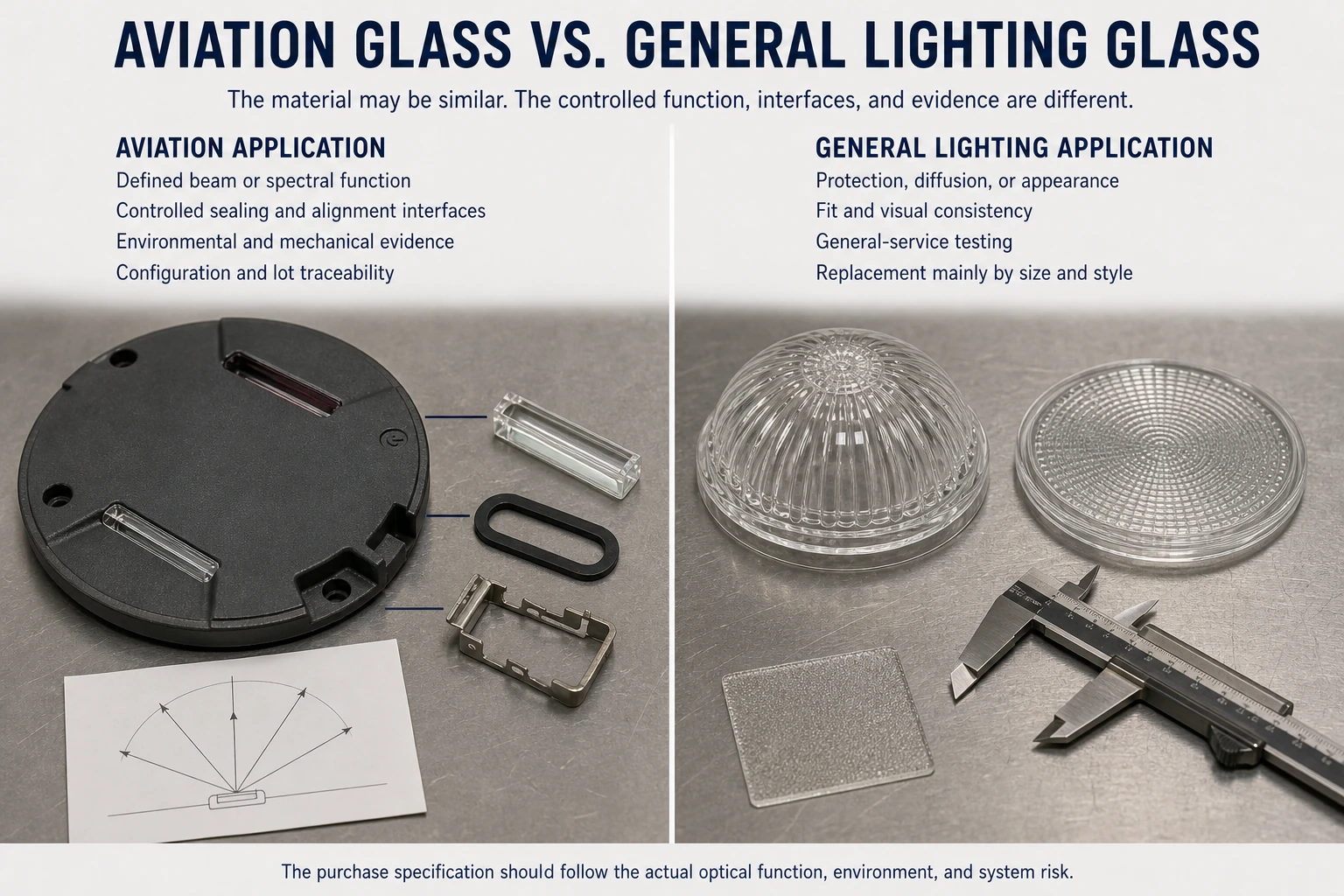
- The main difference is not that aviation glass is always a special chemistry; it is that the component is controlled within a safety- and performance-driven system. Ordinary lighting glass may be accepted primarily by appearance, fit, and general durability. Aviation lighting glass is more likely to have defined optical transmission, color, beam influence, critical dimensions, surface condition, environmental exposure, inspection records, and configuration controls.
- Small variations can have system effects. A prism angle shift can move a main beam. Color-filter thickness or composition can alter chromaticity and intensity. Edge chips can reduce strength or damage a seal. Molded waviness that is harmless in a decorative globe can create unwanted structure in a narrow aviation beam. A coating that performs well at room temperature may change after humidity, abrasion, or thermal cycling.
- This does not mean every aviation component needs imaging-grade tolerances or the most expensive material. Over-specification increases cost, tool complexity, and scrap without improving the fixture. The correct approach is to identify the glass characteristics that influence the approved system requirement, then specify measurable limits for those characteristics. A controlled, application-specific commercial glass can be a better engineering choice than a premium optical grade whose properties do not address the actual failure mode.
The practical distinction is therefore application control: aviation glass earns its specification from the system function, not from a premium-sounding material label.
Is every transparent aviation component a lens?
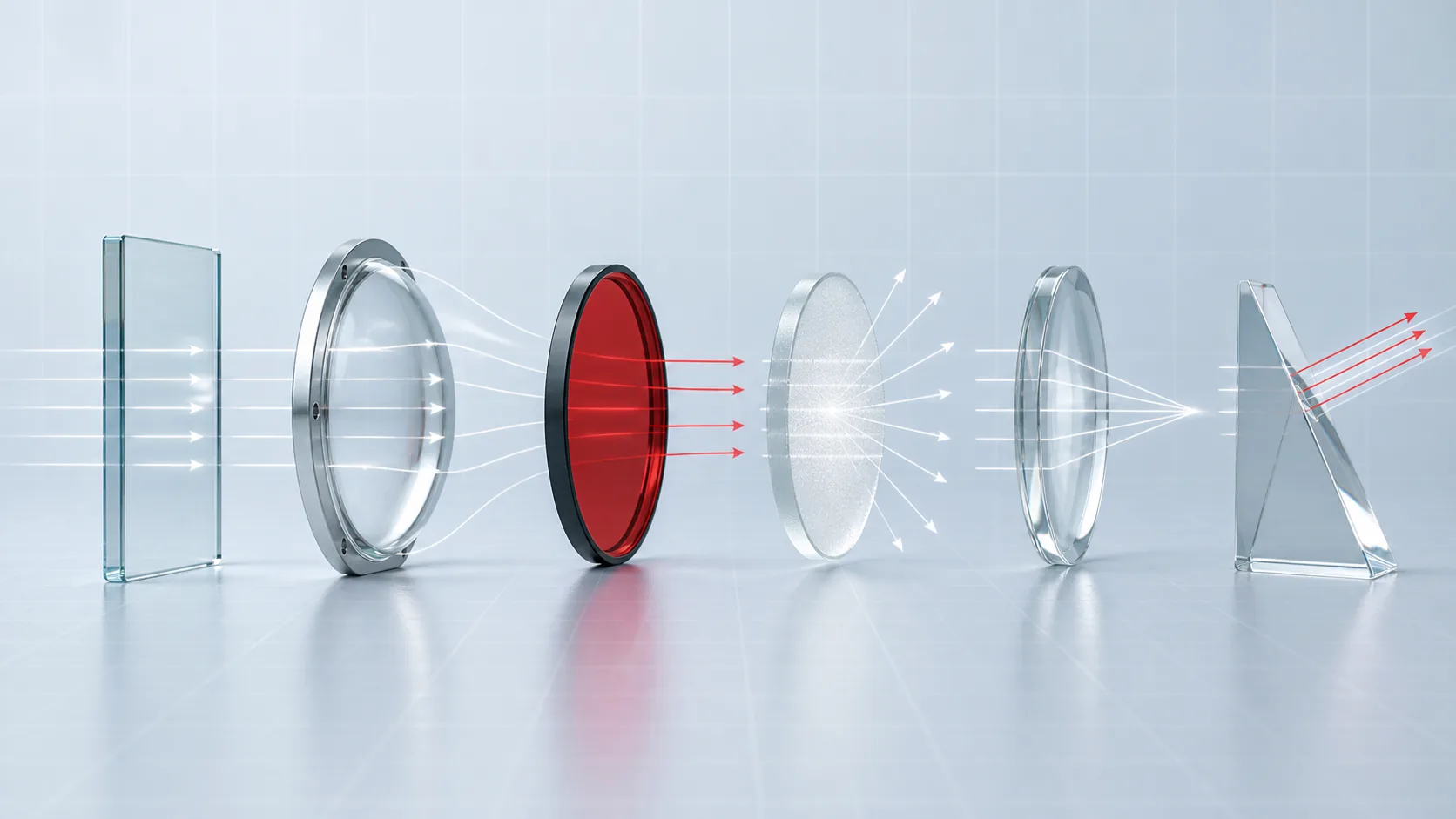
Short answer: no. “Transparent component” describes appearance; lens, prism, filter, diffuser, window, and cover describe optical or mechanical jobs.
- Window: protects a sensor or light path while adding as little beam or image change as possible.
- Cover: provides environmental or structural protection and may tolerate controlled optical power.
- Filter: changes spectral transmission, color, or detector response.
- Diffuser: deliberately spreads light or hides individual sources.
- Lens: changes convergence, divergence, or image formation.
- Prism: redirects light and may create a tightly controlled angular distribution.
One molded part can perform several of these functions at once. A red aircraft-light cover may protect, filter, and shape the signal; an in-pavement prism may redirect the beam and help seal the optical opening. The drawing and inspection plan therefore need to describe the functions being controlled, not merely call the part “glass” or “lens.”
Why is the glass component part of the optical system rather than just a shield?
Light changes direction and intensity whenever it passes through glass interfaces.
Curvature, prism angle, refractive index, thickness, surface texture, coatings, and assembly position can all alter the outgoing distribution. Even a nominally flat protective window introduces reflection losses at two surfaces and may add wedge, ghost reflections, or stress birefringence. A colored cover further changes the spectrum, which affects both measured chromaticity and luminous intensity.
The effect becomes critical when a fixture has a narrow acceptance envelope. FAA airfield-light specifications define beam coverage and intensity regions for complete fixtures, while PAPI requirements control the red/white transition at very small angular scales. The glass manufacturer does not certify the complete fixture, but glass variation can determine whether the fixture passes or fails qualification and production photometry.
Treat the glass, source, reflector, seals, and mechanical datum scheme as one tolerance chain. Optical simulation should use measured or controlled material data rather than a generic refractive index when performance is sensitive. Prototype testing should be conducted with production-representative glass, surface finish, filter color, and mounting stress. If the final assembly compresses a gasket around the optic, verify that the installation does not tilt, distort, or chip it.
OEM project input checklist
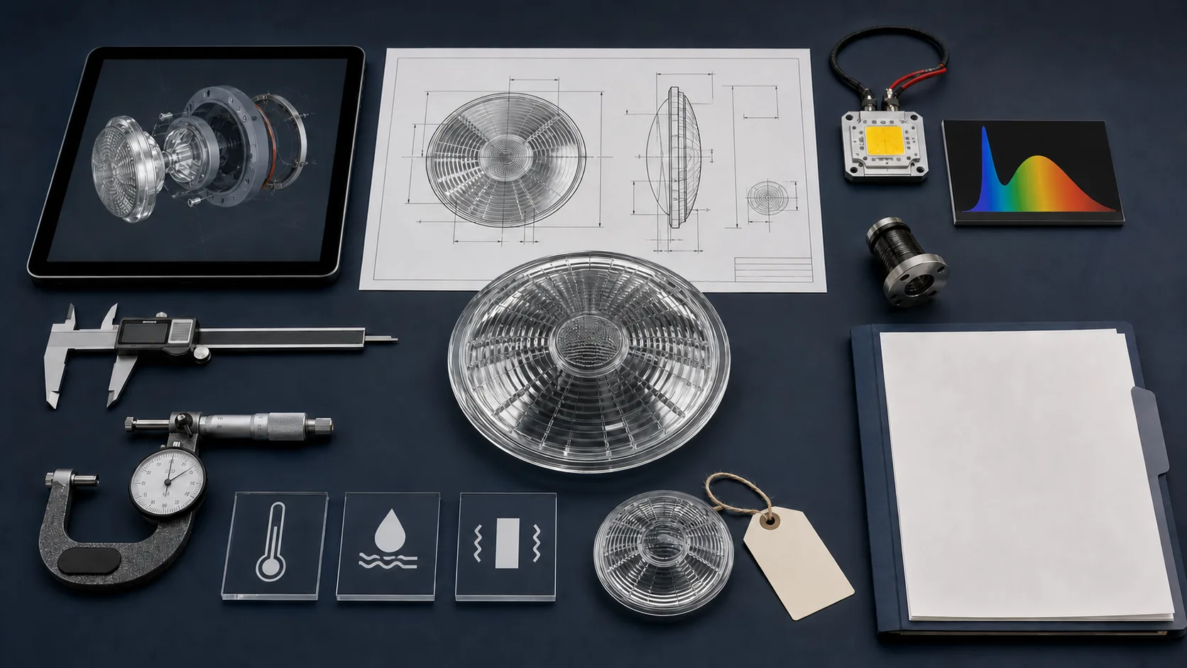
A custom aviation lighting glass project should begin with one controlled input package. The supplier does not need every answer on day one, but unresolved items should be identified before tooling or qualification samples are approved.
| Input category | Define before design freeze | Why it matters |
|---|---|---|
| Optical target | Beam, intensity, color or spectrum, transmission, diffusion, glare and viewing envelope | Determines which surfaces, dimensions and material properties are function-critical |
| Drawing and assembly datums | 2D drawing, 3D model, clear aperture, mounting seats, orientation, seals, fasteners and allowable contact | Connects optical geometry to fit, alignment, stress and interchangeability |
| Source and spectrum | Lamp or LED type, spectrum or bin, emitting geometry, operating point, dimming and temperature | Color, intensity and beam shape depend on the source-and-glass combination |
| Environment | Operating and storage temperature, thermal shock, vibration, impact, water, UV, fluids, abrasion and cleaning | Sets material, coating, edge, mounting and validation requirements |
| Inspection and documents | Critical dimensions, optical tests, defect zones, sampling, certificates, traceability and change notification | Turns system needs into repeatable production controls |
| Volume, samples and change control | Annual demand, lot size, prototype route, master samples, tooling ownership, approval authority and revision process | Aligns manufacturing economics with the controlled configuration |
When the design replaces a legacy part, include the fixture manufacturer and model, approved part number, known revision, representative samples, installation history, and authority for approving change. A physical sample can support measurement, but it cannot reveal every hidden tolerance or qualification requirement.
Why do optical performance and mechanical reliability have to be designed together?
Optical and mechanical decisions often compete.
Increasing thickness can improve handling robustness but add absorption, mass, thermal gradients, and a different optical path. A highly polished sharp edge may fit an optical model yet be vulnerable to chipping. Chemical strengthening can improve damage resistance in suitable glass but may introduce dimensional or optical considerations that must be characterized. A coating may improve transmission while becoming the most abrasion-sensitive surface in the assembly.
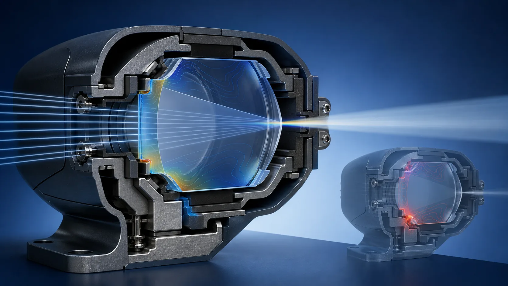
The fixture also loads the glass. Uneven gasket compression, rigid point contact, incorrect torque, or a mismatch in thermal expansion can create stress that was absent during free-state inspection. An optic that passes dimensional checks on the bench can shift its beam after clamping. Conversely, relaxing an optical tolerance without analysis may produce a mechanically robust part that cannot meet the fixture photometric requirement.
Use a joint design review covering ray path, thermal path, supports, seal compression, edge clearances, tolerance stack, and service access. Define which surfaces control optical alignment and which carry mechanical load. Wherever possible, avoid making a fragile optical edge a hard assembly datum. Qualification should use the intended mounting condition, and incoming inspection should focus on component attributes that correlate with fixture performance. This systems approach reduces late redesign more effectively than maximizing any single glass property.
A reliable design is one in which optical output remains acceptable after real mechanical and environmental loads, rather than one that optimizes strength or photometry in isolation.
Why is glass still used when transparent polymers are lighter?
Transparent polymers can reduce mass, absorb impact, and enable complex molded shapes. Glass remains attractive for a different set of reasons, so the choice is a trade-off rather than a hierarchy.
Where polymers often lead. Low density, ductile impact behavior, integral clips or bosses, and rapid molding can be valuable for cabin parts or lightly loaded covers. Their limits may include surface abrasion, coating dependence, thermal movement, UV aging, and chemical sensitivity.
Where glass often leads. Scratch resistance, dimensional stability, heat resistance, stable color, and long-term optical clarity favor glass in exposed runway optics, hot landing-light covers, filters, and sensor windows. The trade-off is brittle fracture behavior and the need to protect edges from point contact.
How to choose. Compare the complete installed solutions—including hard coats, thickness, seals, replacement interval, cleaning, rain erosion, temperature, and qualification history. The best material is the one that maintains the required optical function with acceptable lifecycle risk, not simply the lightest or hardest candidate.
Choose a guide by engineering task
| Current task | Start with | Typical output |
|---|---|---|
| Identify the governing requirement and approval owner | Standards & Compliance | Compliance matrix and responsibility split |
| Develop or replace an airfield optic | Airfield Lighting Glass or In-Pavement Prisms | Application-specific optical and mechanical requirements |
| Control a PAPI transition | PAPI Optical Components | Source-filter-lens tolerance and verification plan |
| Select material or process | Materials & Manufacturing | Material/process shortlist and DFM risks |
| Diagnose field degradation or breakage | Reliability & Maintenance | Inspection evidence and root-cause path |
| Prepare an RFQ or legacy-part replacement | Development & Procurement | Controlled input package and approval workflow |
Detailed topic guides
Use this page for the system-level overview and shared technical terminology. Continue with the focused guide that matches your application, qualification task, material decision, failure investigation, or RFQ.
Lighting guides cover visible-signal and illumination components. Display covers and sensor windows are separated because they preserve information or detector performance rather than produce an aviation light signal.
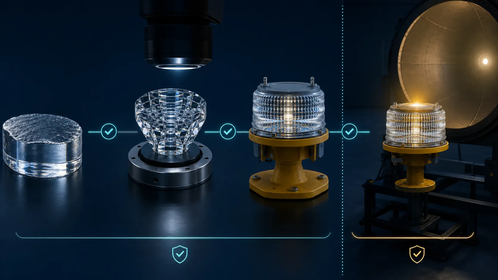
Match FAA, ICAO, SAE and RTCA requirements to the complete equipment, component evidence, document revision and responsible organization without overstating glass-part certification.
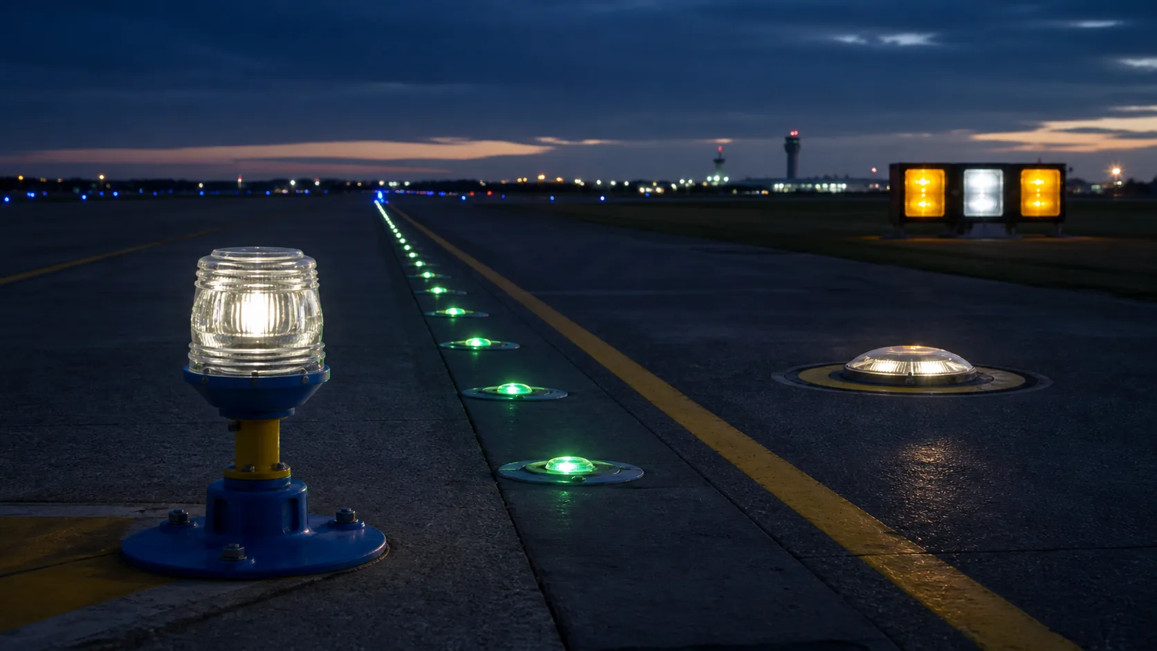
Compare runway, taxiway, elevated, obstruction, heliport and sign-light glass by optical function, installation style, exposure and replacement risk.
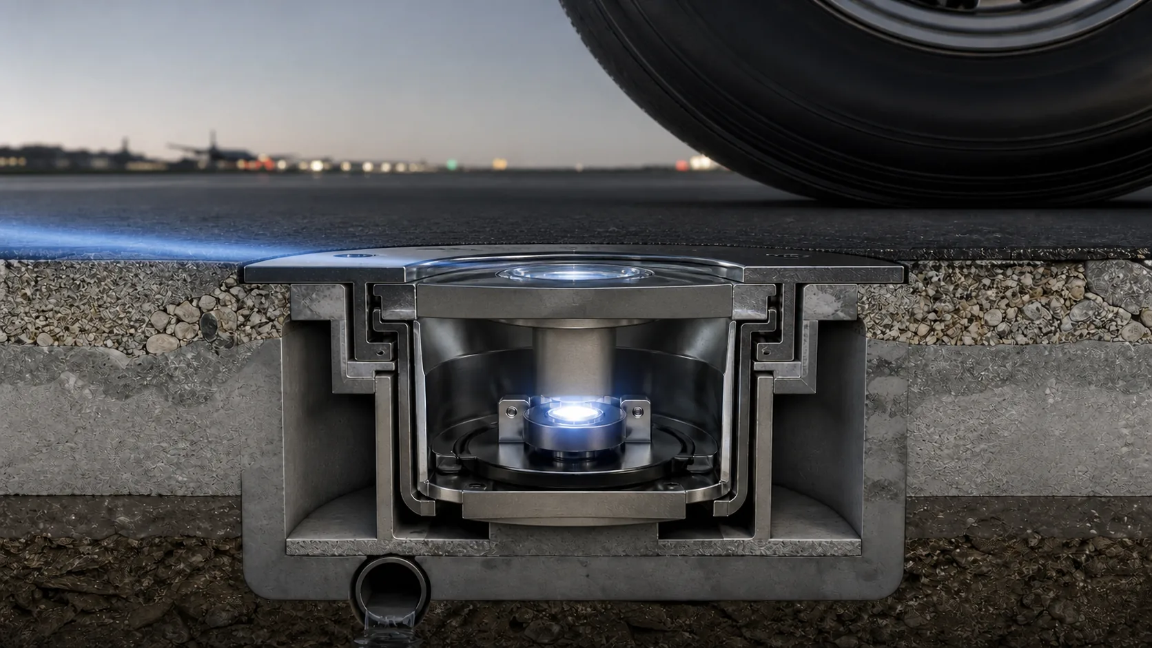
Specify prism geometry, datums, sealing faces, load paths, surface defects and production tests for in-pavement airfield fixtures.
Control the PAPI red/white transition through source, filter, lens, housing datums, temperature management, inspection and complete-unit verification.
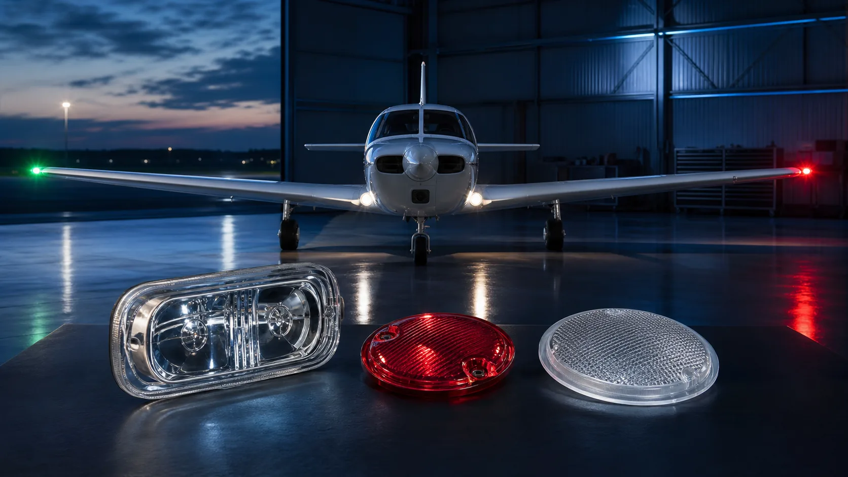
Select glass for aircraft signal, landing, emergency and cabin lighting according to optical duty, erosion, vibration, fluids, heat and weight.
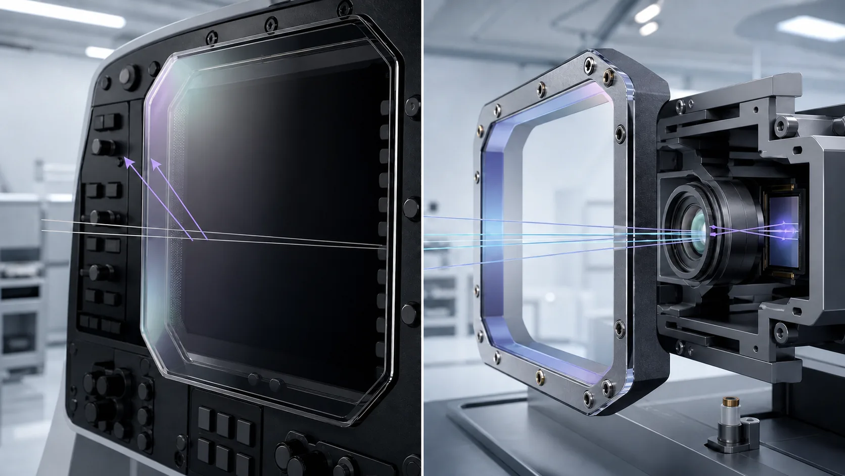
Define display covers and sensor windows by reflection, distortion, spectral band, wedge, flatness, condensation control and coating durability.
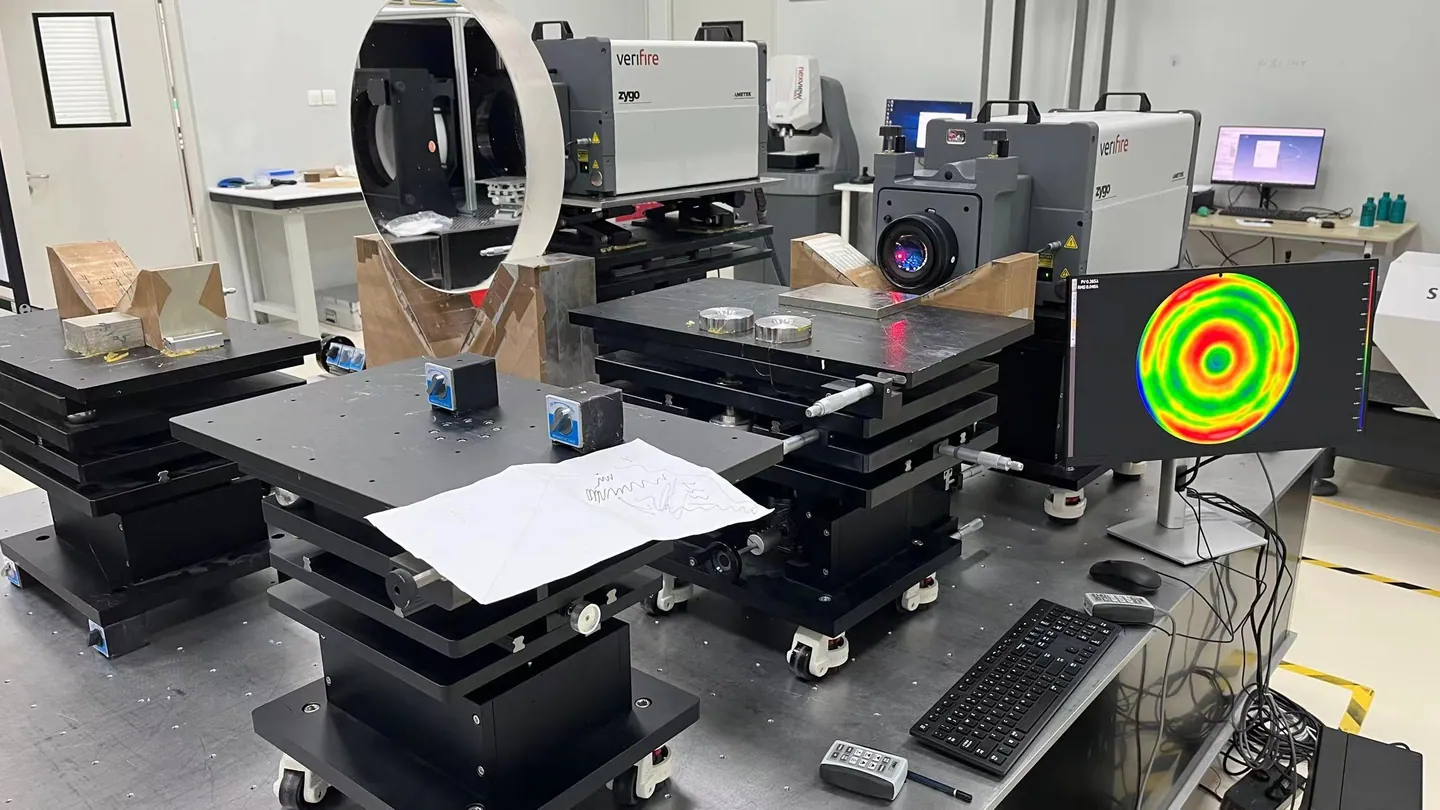
Translate beam, transmission, chromaticity, source spectrum, scatter and refractive-index requirements into measurable optical tolerances.
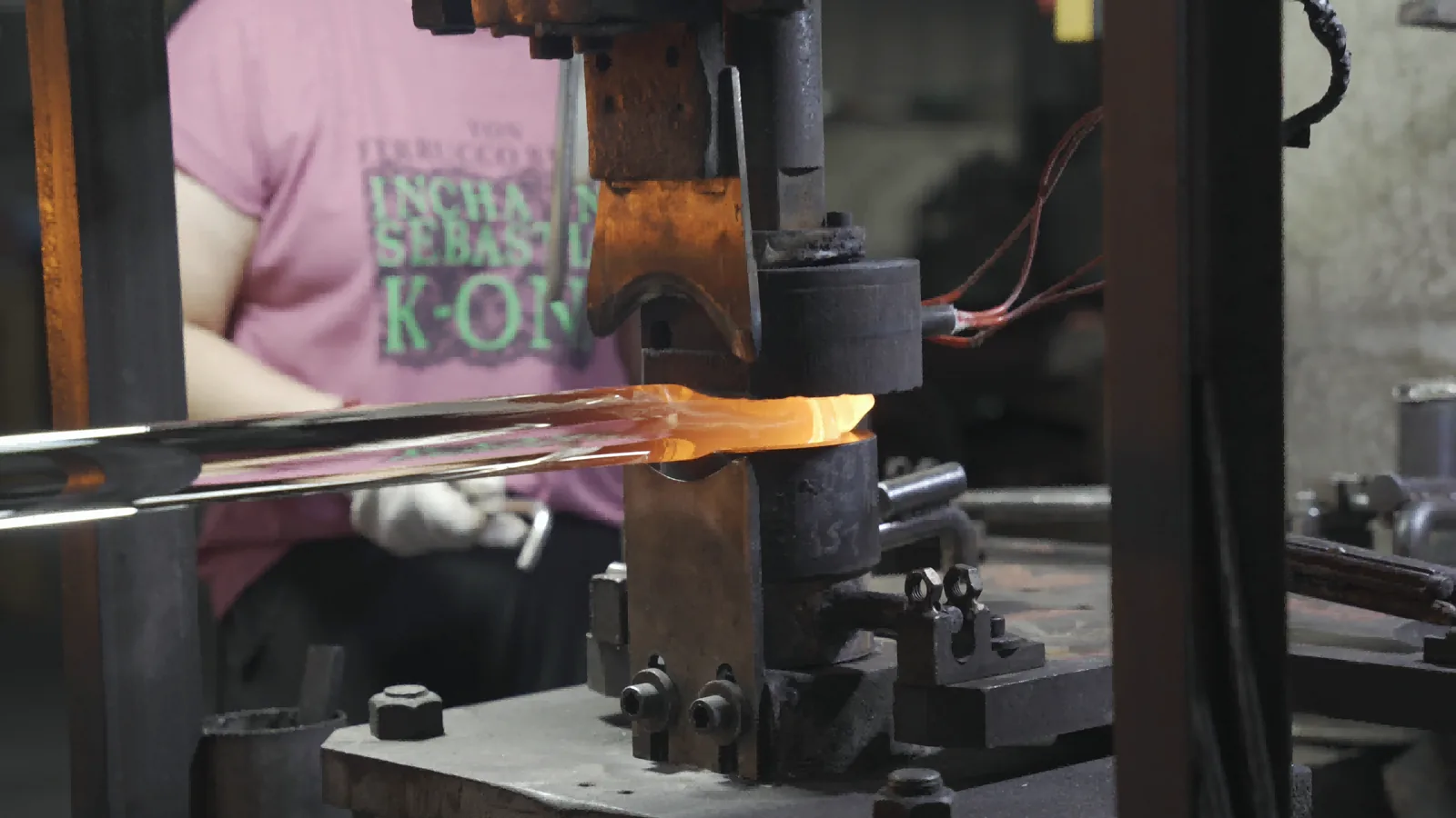
Compare glass and non-glass materials with molding, machining, annealing, polishing, strengthening, printing and coating routes.
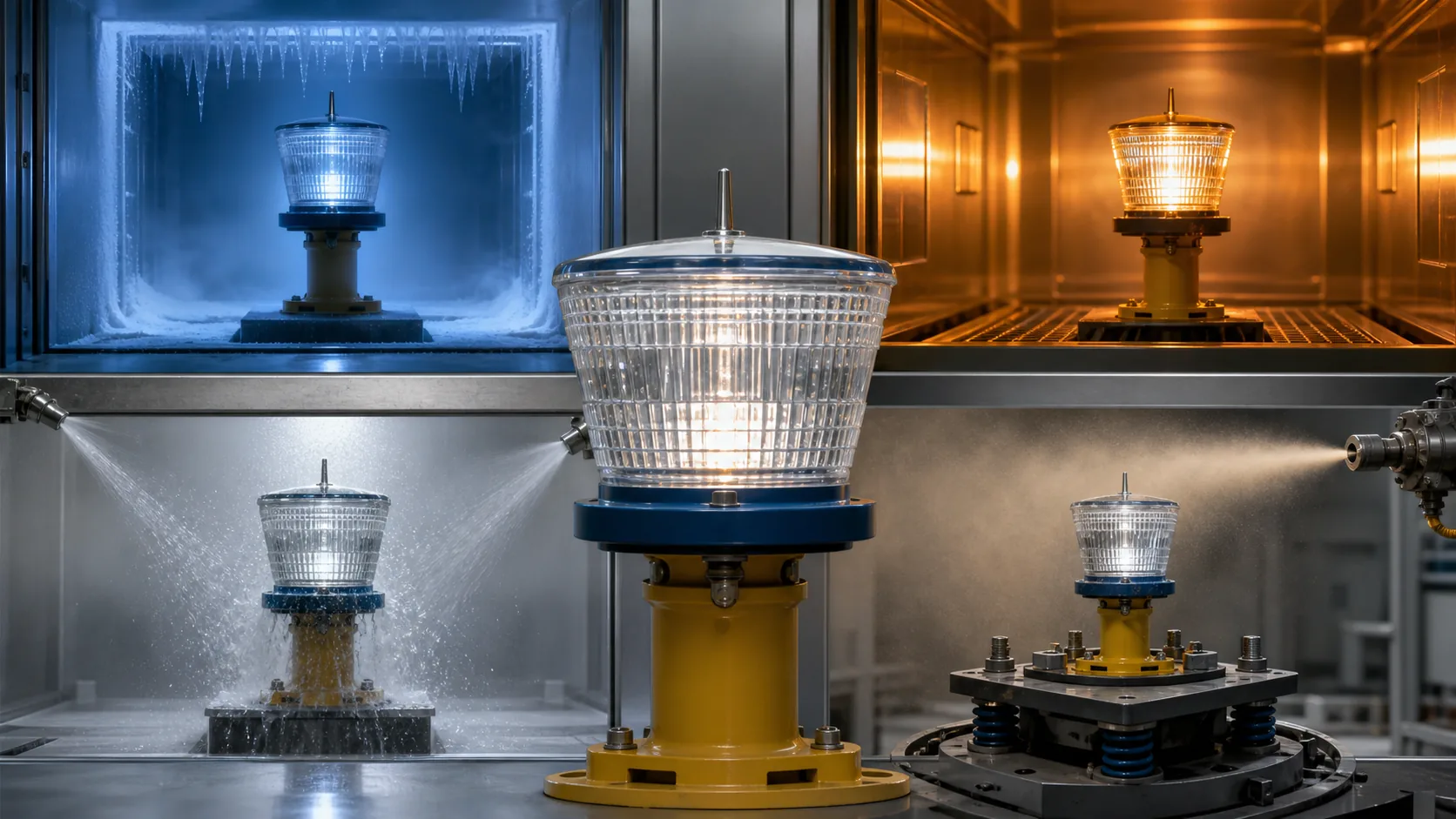
Connect thermal, mechanical, chemical and weather exposure to test evidence, inspection criteria, maintenance actions and root-cause analysis.
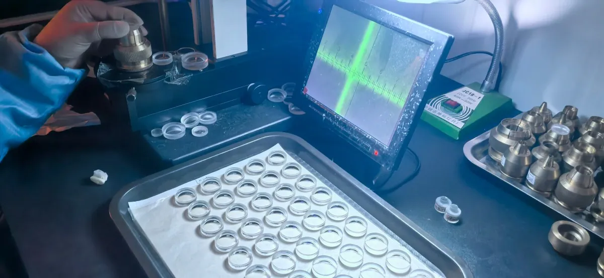
Move from drawings or legacy samples to DFM, prototypes, approval, traceability, controlled change, second sourcing and long-term supply.
Contact Us
Your feedback fuels our growth, and your questions drive our solutions.
We value your feedback, inquiries, and suggestions. Please feel free to get in touch with us
General inquiries
Please contact us via sales@bo-glass.com, and we will reply to you as soon as possible.
Interested to work with us
Drop your resume at info@bo-glass.com
and we will get back to you shortly.
We uses the contact information you provide to us to contact you about our relevent content, products, and services.