
In-Pavement Runway & Taxiway Light Prisms
Optical geometry, sealing, loading, durability, inspection, and replacement considerations for in-pavement airfield light prisms.
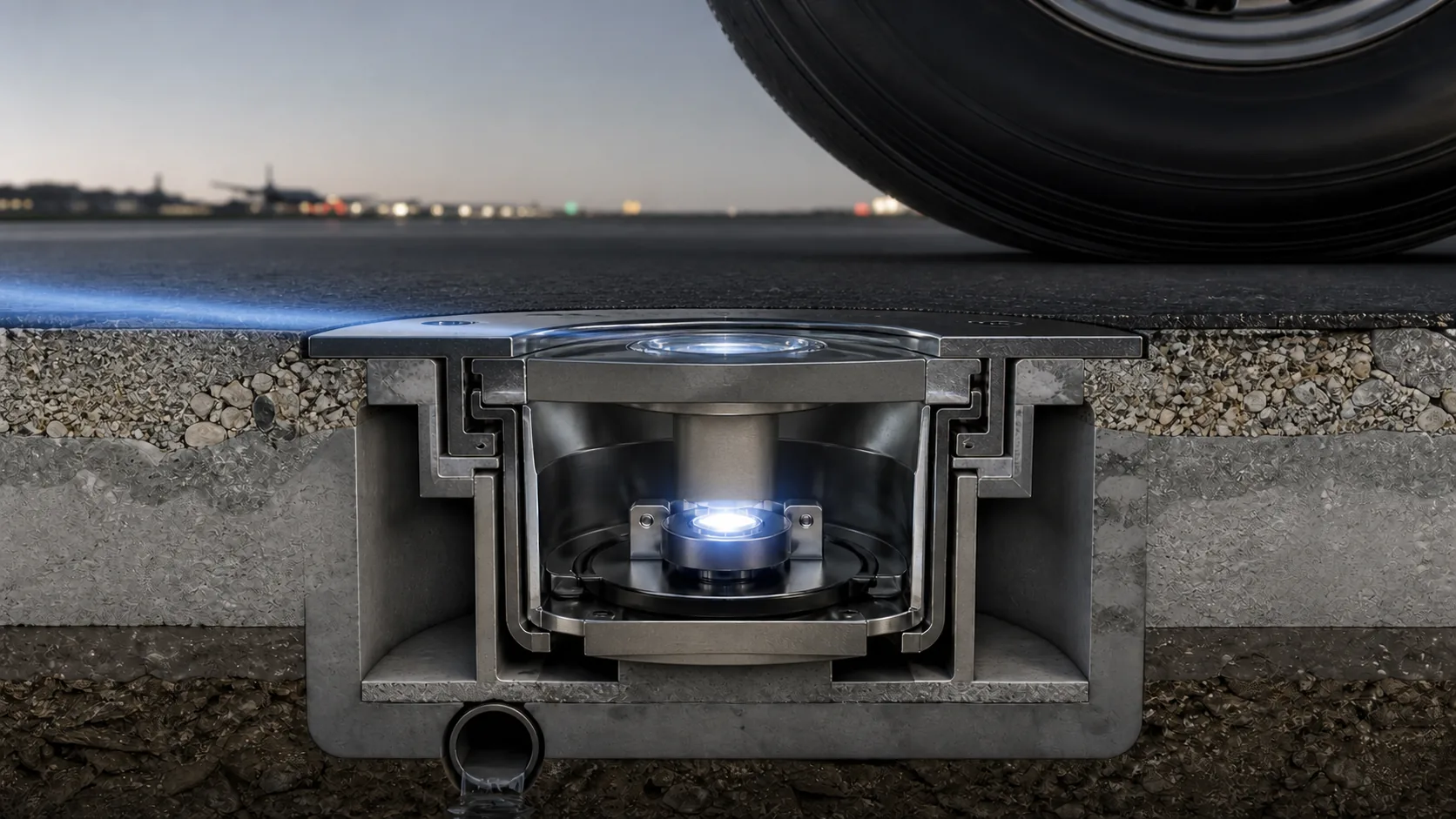
In-Pavement Runway and Taxiway Light Optics
An in-pavement prism has to solve two conflicting problems: it must project a controlled beam only a few degrees above the pavement, yet remain protected inside a fitting exposed to wheel loads, rubber deposits, water, grit, and snow-removal activity. The useful question is therefore not simply whether the glass is strong. It is how optical faces, buried edges, seals, housing support, and surface contamination interact in the installed light.
What does an in-pavement runway light prism do?
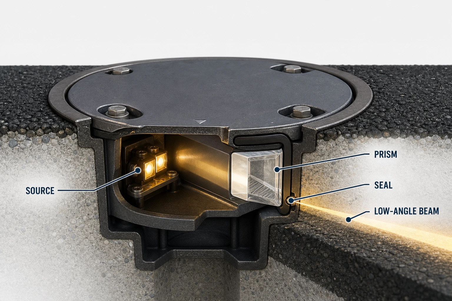
An in-pavement prism redirects light from a source and optical chamber into a low-angle beam visible to an approaching or taxiing pilot. Its refracting faces, material index, installed orientation, and position relative to the source determine beam direction and spread. It also forms part of the environmental boundary at the optical opening, although the housing and seal create the complete barrier.
The prism is subjected to a difficult combination of conditions: mechanical load transmitted through the fixture, vibration, impact, thermal cycling, water, rubber deposits, sand, deicing chemicals, and repeated cleaning. Optical performance must remain acceptable after the complete fixture is exposed to qualification tests. Edge integrity and seating geometry are therefore as important as the polished aperture. For a new design, develop the prism together with the source, reflector, housing, masks, and pavement geometry. For an existing design, preserve material, prism angles, datum relationships, color, and seal interface unless the design authority approves a change. Manufacturing feasibility can be reviewed from drawings or representative samples, while fixture-level optical validation remains the OEM’s responsibility.
Which prism dimensions most strongly affect beam position?
The most influential dimensions are usually the angles and relative positions of the entrance and exit surfaces, the datum face that seats the prism, and the installed relationship between the optic and source. Wedge, decenter, curvature, wall thickness, and local surface form may also matter. The sensitivity depends on the optical architecture; a tolerance that is critical in one fixture can be unimportant in another.
A ray-trace sensitivity study should rank each variable by its effect on beam center, coverage, and intensity. That ranking becomes the basis for drawing tolerances and inspection. Do not specify every dimension at the same tight limit. Instead, control the functional chain from mounting datum to optical surface. If molded features cannot be measured directly with conventional tools, agree on a profile method, fixture gauge, CMM strategy, optical comparator, 3D scan, or functional beam test. Correlate component data with fixture photometry during development. If beam shift tracks one angle, strengthen that control. If variation is dominated by source position or housing machining, tightening the glass alone will not solve the problem. Functional evidence prevents a costly tolerance stack built on assumptions.
Why can a visually perfect prism still fail fixture photometry?
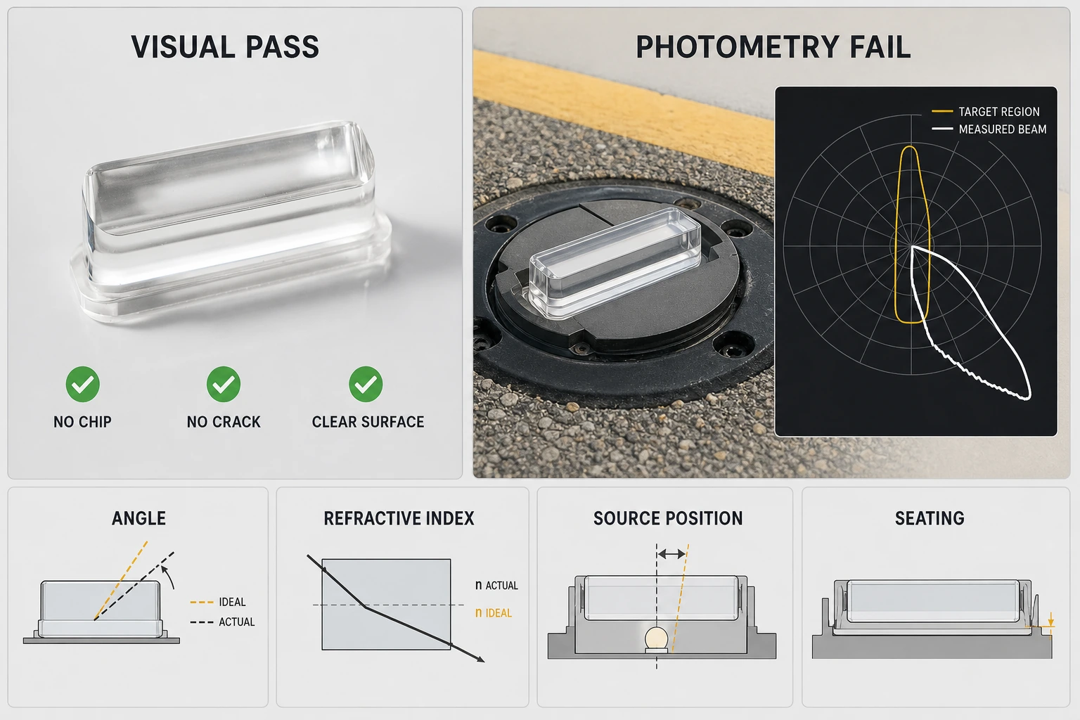
Visual inspection detects chips, cracks, inclusions, haze, stains, and obvious molding defects, but it cannot reliably measure optical angle, refractive behavior, source alignment, or beam distribution.
A prism can look flawless and still have a small angular error, wrong orientation, incorrect refractive index, subtle surface form deviation, or thickness change that moves energy outside the required photometric region.
The fixture may also be responsible. The source can be off position, the reflector tilted, the housing mask incorrect, or the prism unevenly seated. A colored prism may meet visual color expectations yet lose too much intensity or miss chromaticity at operating temperature. Assembly stress can change alignment after free-state inspection.
Use layered verification. Visual and dimensional inspection protect workmanship and interfaces. Material and spectral controls protect index and color. A component-level optical check can detect beam deviation or prism-angle error. Complete-fixture goniophotometry proves the system requirement. Production controls should be chosen from development correlation: if a simple component measurement predicts fixture performance, use it routinely; if it does not, retain appropriate fixture sampling.
For this reason, fixture photometry—not visual appearance—remains the decisive test of whether a runway-light prism is optically interchangeable.
How should a bidirectional prism assembly be controlled?
- A bidirectional fixture emits in two opposing directions and may use clear or different colored channels. The risks are swapped components, rotated prisms, incorrect color direction, asymmetrical seating, and cross-talk between optical paths. The part and assembly design should make the correct configuration obvious and, ideally, physically enforce it.
- Use asymmetric keys, dedicated pockets, durable orientation marks, unique part numbers, or controlled color identifiers. Define the runway-reference direction on the drawing and work instructions. Inspection should verify both direction and color; relying on operator memory is weak configuration control. If two prisms appear similar, use mistake-proof packaging and line-side segregation.
- Photometry must be evaluated in both directions because one channel can pass while the other fails. Check for unwanted light across the center or into masked zones. In service, maintenance instructions should prevent left/right reversal after cleaning or seal replacement. A component supplier should package pairs or kits when that reduces assembly error and should preserve traceability to each color lot. The final fixture marking remains essential so installers align the unit correctly to the runway or taxiway centerline.
How do aircraft wheel loads reach the glass prism?
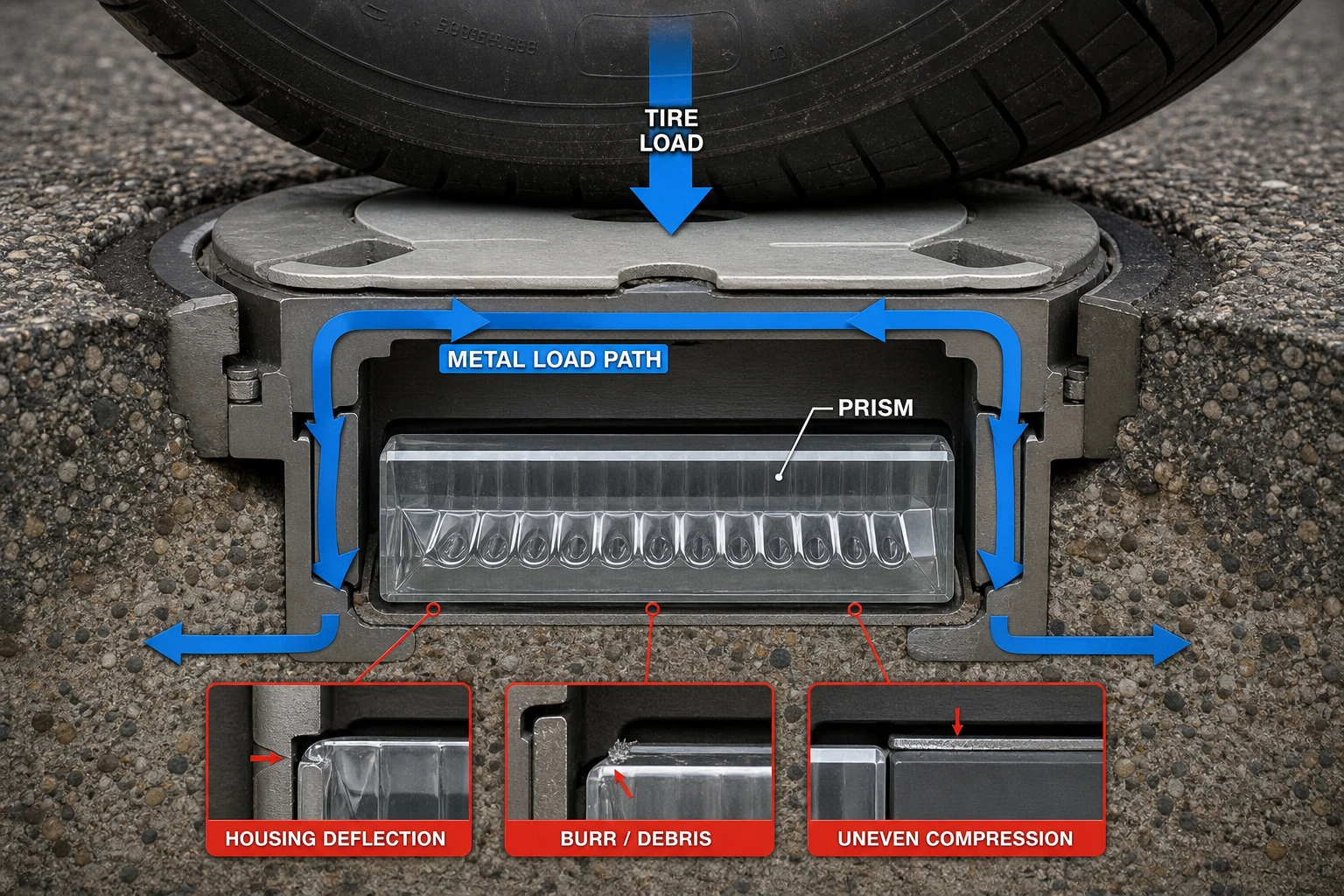
Load path. An aircraft tire first loads the metal top structure of an in-pavement fixture. The housing, adapter, bolts, and base are intended to carry that load around the optical opening. Glass becomes highly stressed when housing deflection, a burr, trapped debris, excessive seal compression, or incorrect assembly creates local contact at the prism edge or seat.
What the FAA numbers mean. FAA AC 150/5345-46F applies a complete-fixture static load equal to 450 times the defined top area in square inches, together with an 11,000 lb (4,989.5 kg) shear requirement. These values describe the configured light and its load path; they are not standalone strength ratings for a loose prism.
- Housing analysis shows where deflection can reach the glass.
- Prism drawings control seat geometry, edge clearance, critical chips, and contact surfaces.
- Assembly controls remove burrs and debris and preserve gasket compression and fastener sequence.
A thicker prism is not an automatic cure: it can reduce clearance and increase point loading. Fracture-origin analysis is more useful than adding material before the actual load path is understood.
What is hydraulic impact, and why is it important for inset lights?
What happens. Water trapped over an inset light transmits a short pressure pulse when a tire or external load strikes it. Because water is nearly incompressible, the window, seal, and housing can see a very different stress pattern from a dry static load.
FAA fixture example. In AC 150/5345-46F, the configured light is submerged in about 0.5 in (13 mm) of water beneath a 1.75 in (44.5 mm) piston. A 5 lb (2.3 kg) steel ball is dropped 6 ft (1.8 m) onto the piston, and the event is repeated five times. Mechanical failure, optical damage, or water entering the optical cavity causes rejection.
What the result teaches. A failure may come from glass damage, seal extrusion, insufficient support, trapped volume, or housing deformation. That is why a coupon impact number cannot replace the assembly test. Useful post-test inspection includes cracks, chips, looseness, leakage, and beam change.
Why are sealing surfaces on a runway prism critical?
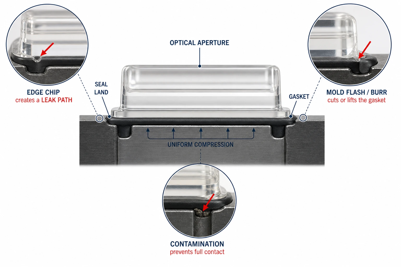
The sealing surface determines how consistently the gasket contacts the prism and housing.
Waviness, chips, mold flash, roughness, contamination, or dimensional variation can create leak paths. Excessive roughness may damage a seal; an overly sharp edge can cut it during assembly. If the prism sits unevenly, the beam can shift and local stress can rise.
Define the seal land separately from the optical aperture. Specify flatness or profile only to the degree required by the seal design, along with edge breaks, surface condition, and no-defect zones. Consider whether a molded surface is adequate or whether grinding is necessary. More machining is not automatically better; it can add cost and subsurface damage if the functional requirement is not clear.
Validate the interface with the actual gasket material, compression, lubricant or assembly aid, temperature range, and housing. Perform leakage testing after mechanical and thermal exposures because seals can pass initially and fail after movement. In production, protect the seal land from handling scratches and chips, and clean it before assembly. A reliable optical chamber is a system outcome involving prism, gasket, housing, fasteners, and process control.
Can a coating make a runway prism self-cleaning?
No coating should be described as universally self-cleaning without strong field evidence. Hydrophobic or low-surface-energy coatings can change water behavior and may reduce adhesion of some contaminants, while hard or anti-reflective coatings can address other needs. Runway contamination includes rubber, fuel or oil residues, dust, chemicals, and mechanical abrasion—one surface treatment rarely solves all of them.
The coating also becomes part of the optical and maintenance system. It can change transmission, reflection, color, and surface stress. Its performance may decline after UV, salt, deicing fluid, thermal cycling, sand, rubber-removal chemicals, or repeated wiping. Coating edges and masked seal lands require control. A damaged coating can create patchy transmission that is harder to diagnose than uniform uncoated wear. Specify the exact problem and verification method: contact angle alone is not evidence of reduced runway maintenance. Test optical performance before and after representative contamination, cleaning, abrasion, and environmental exposure. Compare lifecycle cost and field serviceability. If the coating cannot be repaired or identified in service, include a clear replacement criterion and configuration mark.
What causes prism cracking in an inset fixture?
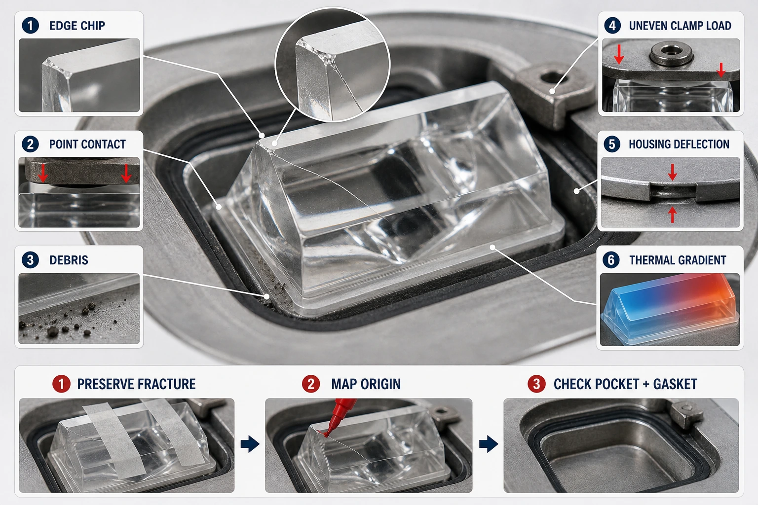
Common causes include edge damage, hard point contact, debris under the prism, excessive or uneven clamp load, housing deformation, seal misplacement, thermal shock, impact, material or process defects, and incompatible dimensional stack-up.
Cracks can also start from grinding damage or an inclusion, but assembly and handling factors are often equally important.
Glass is strong in compression but sensitive to tensile stress concentrated at flaws. A small chip in a highly stressed edge can matter more than a larger cosmetic mark in a low-stress zone. Temperature gradients and differences in thermal expansion among glass, metal, and seal can add stress. Repeated loads can extend an existing crack even if the initiating event occurred earlier.
Investigate fractures systematically. Preserve pieces, map the origin, record installation and torque, inspect the pocket and gasket, check dimensions, and review recent maintenance or impact. Compare with retained samples and production records. Do not conclude “weak glass” solely from a broken part. Corrective action might involve edge processing, packaging, seal design, housing stiffness, assembly instructions, or material—not necessarily greater thickness.
How should surface defects on a runway prism be specified?
- Use functional zones. The optical aperture needs limits for defects that scatter, block, or redirect light. The sealing land needs limits for chips, waviness, flash, and scratches that could create leaks. Loaded or exposed edges need controls based on strength and assembly. Hidden surfaces can often accept wider cosmetic variation if it does not affect fit or durability.
- Avoid one generic scratch/dig or cosmetic standard over the whole molded part. Imaging-optics notation may be inappropriate for a non-imaging illumination prism, while an appearance-only limit may miss a beam-critical ripple. Define defect type, size, quantity, spacing, location, inspection lighting, magnification, and reference samples. For bubbles, stones, cords, mold marks, laps, pits, or checks, state whether rejection is based on optical blockage, stress risk, or appearance.
- Validate the limits with photometry and strength evidence. If a defect within the proposed limit has no measurable effect and no structural relevance, tighter control adds cost without value. If small defects at a specific edge cause fracture, create a protected no-chip zone there. Photographs can supplement but should not replace measurable criteria and approved boundary samples.
What production tests are appropriate for inset-light prisms?
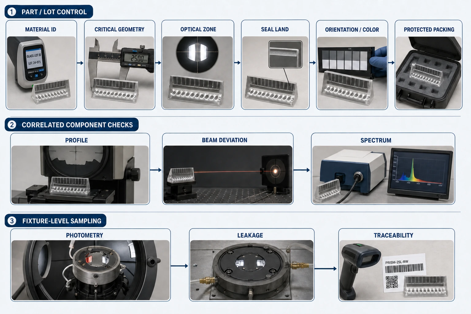
Production control for an inset-light prism works best as three layers rather than one oversized final inspection:
- Every part or lot: material identity, critical prism angles and datums, optical-zone defects, seal-land geometry, orientation, color or spectrum, and protected packaging.
- Correlated component checks: a master gauge, profile scan, collimated-beam deviation test, or spectral measurement that has demonstrated a relationship to fixture performance.
- Fixture-level sampling: photometry and leakage performed by the equipment manufacturer under the approved production plan.
FAA AC 150/5345-46F requires every finished in-pavement optical assembly to be leak-tested at 20 psi (137.9 kPa), with photometric sampling and production records retained for three years. Those are finished-fixture obligations, not tests that a loose prism independently satisfies.
Production control is most effective when rapid component checks are correlated with periodic fixture photometry instead of trying to repeat full qualification on every glass part.
Official and standards references for this guide
Source status was reviewed on August 12, 2026. The contract, certification basis, approved equipment configuration and controlled document revision determine actual applicability. Obtain authorized copies of paid standards.
- FAA, AC 150/5345-46F for complete in-pavement fixture requirements, qualification tests and production obligations.
- FAA, AC 150/5340-30 - Design and Installation Details for Airport Visual Aids.
- FAA, Airport Lighting resources, including the FAA-hosted in-pavement lighting design, installation and maintenance document.
- ISO, ISO 10110-7:2017 - Surface imperfections, when the project elects to use ISO optical-drawing notation for relevant finished surfaces.
Contact Us
Your feedback fuels our growth, and your questions drive our solutions.
We value your feedback, inquiries, and suggestions. Please feel free to get in touch with us
General inquiries
Please contact us via sales@bo-glass.com, and we will reply to you as soon as possible.
Interested to work with us
Drop your resume at info@bo-glass.com
and we will get back to you shortly.
We uses the contact information you provide to us to contact you about our relevent content, products, and services.