
CNC machining in Soda-Lime Glass


Float Glass Fabrication Capabilities
Max. Processing Size: | Sheets over 5m in length, large-format panels |
Min. Part Size: | Precision micro-components down to 10mm. |
Cutting Tolerance: | ±0.1 mm(CNC/Waterjet),±0.05 mm(Laser) |
Drilling/Milling Tolerance: | ±0.1 mmposition &diameter) |
Edge Profile Tolerance: | ±0.1 mm |
Standard Thickness Range: | From 1.5 mm and above. |
Ultra-Thin Processing Capability: | Down to sub-1.0 mm(e.g.,0.3-0.7 mm for specialty applications) |

What are the ingredients of clear float glass?
1.High Calcium Content (7.7%–11.8%): This range ensures that the glass hardens quickly during formation, preventing excessive stretching and maintaining structural integrity. The controlled calcium levels help achieve a fine-grain structure, enhancing overall durability.
2.Medium Magnesium Levels (2.5%–4.5%): By keeping magnesium within this spectrum, manufacturers mitigate brittleness-related issues caused by higher calcium content. This balance contributes to the glass’s flexibility and resistance against cracking under stress.
3.Low Aluminum Content (<2.0%): Reducing alumina prevents the glass from becoming overly viscous during production, ensuring smoother processing and a clearer final product. Lower aluminum levels also contribute to improved thermal stability.
4.Trace Iron Levels (≤0.1%): The precise control of iron content minimizes color variations in the glass. During melting, Fe²+ is oxidized to Fe³+, which reduces its ability to absorb light and cause discoloration. Post-melting processes further refine this balance, ensuring consistent clarity.
By adhering to these specifications—SiO₂ (71.5%–72.5%), Na₂O/K₂O (13.4%–14.50%), CaO (7.7%–11.8%), MgO (2.5%–4.5%), Al₂O₃ (<2.0%), Fe₂O₃ (≤0.1%), and SO₂ (<0.30%)— manufacturers achieve float glass that is both strong and visually appealing, suitable for a wide range of applications from residential windows to architectural designs.
This standardized approach not only enhances the quality and consistency of float glass but also streamlines production processes, making it more efficient and cost-effective in industrial settings.
| Oxide Introduced | Raw Material | Characteristics |
| SiO₂ | Quartz Sand (Silica Sand) | Pure silica sand is white, with SiO₂ content over 99% |
| SiO₂ | Sandstone | High-quality sandstone is white or light blue, with a density of 2.50–2.65 g/cm³ |
| Al₂O₃ | Feldspar | Density: 2.50–2.70 g/cm³ |
| Al₂O₃ | Kaolin | Density: 2.40–2.60 g/cm³ |
| Al₂O₃ | Wollastonite | Density: 2.80–2.90 g/cm³ |
| Al₂O₃ | Aluminum Hydroxide | White crystalline powder, density: 3.50–4.10 g/cm³ |
| Na₂O | Sodium Carbonate (Soda Ash) | Available in heavy (white powder, density: 1.50 g/cm³) and light (white powder, density: 0.10–1.00 g/cm³) forms, soluble in water |
| Na₂O | Mirabilite | Includes anhydrous (white or light green crystals, density: 2.70 g/cm³) and hydrated forms (needs dehydration before use) |
| Na₂O | Sodium Hydroxide (Caustic Soda) | White crystalline brittle solid, soluble in water, corrosive |
| Na₂O | Sodium Nitrate | Colorless or light yellow hexagonal crystals, density: 2.25 g/cm³ |
| K₂O | Potassium Carbonate | White crystalline powder, density: 2.03 g/cm³ |
| K₂O | Potassium Nitrate | Transparent crystals, density: 2.10 g/cm³ |
| CaO | Calcite | Appears white, gray, light red, or light yellow |
| CaO | Limestone | Mostly gray, light yellow, or light red, density: 2.70 g/cm³ |
| CaO | Precipitated Calcium Carbonate | By-product of calcium chloride production |
| MgO | Dolomite | Appears blue-white, light gray, or black, density: 2.80–2.95 g/cm³ |
| MgO | Magnesite | White, light red, pale red, or flesh red appearance |
Surface Finishing & Secondary Processing
Screen Printing
Coating (e.g., Sputtering)
Sandblasting
Polishing / Grinding
Acid Etching
CNC Engraving
Painting / Enameling
Applies ceramic-based paint onto the surface, which is then fired at high temperature to fuse into a durable, colored coating.
Advantages of Float Glass in Component Design & Production
Float glass serves as a foundational and preferred material for custom glass components due to its balanced combination of properties, processability, and cost.
Benefits
Optical Clarity & Consistency
Offers high natural light transmittance (typically 88-91%), providing excellent clarity for most non-specialized optical applications.
The float process ensures superior surface flatness and minimal optical distortion compared to other sheet glass methods, ensuring consistent visual quality.
Superior Machinability & Design Flexibility
Excellent material for secondary processing: can be reliably and precisely cut, drilled, milled, edge-worked, and polished using standard CNC and glass fabrication equipment.
Serves as an ideal substrate for a wide range of surface treatments (coating, printing, etching, laminating, tempering) allowing functional and aesthetic customization.
Cost-Effectiveness & Scalability
The continuous float process enables high-volume production of large, uniform sheets at a low cost per unit area, making it economically viable for both prototypes and mass production.
Readily available in a wide range of standard thicknesses (from 2mm to 25mm) and large formats, reducing material constraints and lead times.
Balanced Performance Foundation
Provides a perfect starting material that can be upgraded: It can be subsequently tempered for strength or laminated for safety, allowing designers to specify the base material first and add properties as needed.
Offers good chemical stability and hardness for durability in everyday applications.
Material Stability & Quality
Has consistent, predictable physical and thermal properties (e.g., coefficient of expansion, density), which is critical for precise engineering and machining tolerances.
In summary, clear float glass is the optimal choice for most custom components due to its excellent processability, consistent quality, design versatility, and unmatched cost efficiency for volume production, striking the ideal balance between performance and economy.
Key Limitations to Consider
Limited Optical & Material Performance
Optical Quality: Higher inherent green tint (from iron content) and lower clarity (≈91% max transmittance) compared to ultra-clear low-iron glass (>91%) or specialty optical glass. Not suitable for high-precision optics.
Thermal & Chemical Resistance: Lower thermal shock resistance and higher coefficient of thermal expansion than borosilicate glass. Less resistant to certain chemicals and prone to gradual weathering/aging.
Mechanical Strength: In its annealed state, it is relatively fragile and vulnerable to impact and surface scratches.
Processing & Design Constraints
Secondary Processing Limits: Extensive deep cutting, drilling near edges, or creating very complex internal shapes significantly increases fracture risk. Machining ultra-thin (<1.5mm) sections is highly challenging.
Post-Processing Necessity: Often requires tempering or laminating to meet safety standards, adding cost and lead time. Cannot be used in safety-critical applications in its basic form.
Form Limitations: Primarily supplied as flat sheets. Creating complex 3D shapes requires separate and expensive hot-bending processes.
Application-Specific Drawbacks
Weight: Its standard density (≈2.5 g/cm³) makes large components heavy, impacting support structures and installation.
Sustainability Footprint: The float manufacturing process is energy-intensive. While recyclable, closed-loop recycling into new float glass is complex, often leading to downcycling.
Primary Application Fields for Soda-Lime Glass
Soda-lime glass is the dominant material where clarity, chemical resistance, heat tolerance, and a hard surface are required. Its cost-effectiveness and formability make it ideal for high-volume production across lighting, packaging, consumer goods, and technical industries.
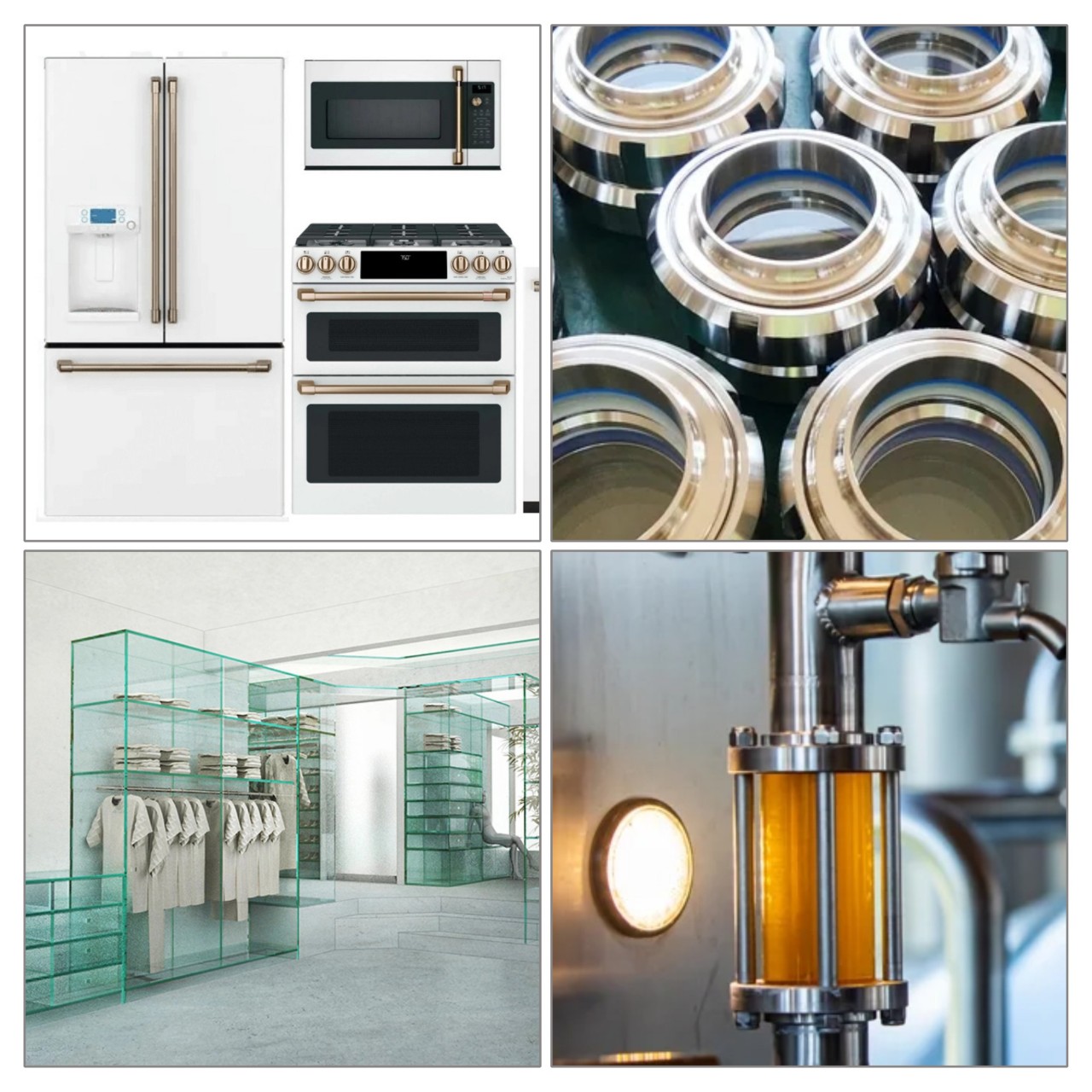
Oven doors, microwave turntables: Cutting, printing, tempering. Refrigerator shelves, stove tops: Cutting, edge grinding, tempering. Control panel covers: Cutting, printing, coating.Oven doors, microwave turntables: Cutting, printing, tempering. Refrigerator shelves, stove tops: Cutting, edge grinding, tempering.
Furniture & Interior Design
Table tops, shelves, cabinet doors: Cutting, edge polishing, laminating, acid etching. Decorative panels, mirrors: Cutting, printing, sandblasting, silvering.
Retail & Display
Display cases, refrigerator lids, signage: Cutting, edgework, printing, laminating. Shelf dividers, protective barriers: Precision cutting, drilling, polishing.
Lighting & Optical
Light fixture covers, diffusers, reflectors: Cutting, bending, sandblasting, coating. Basic lens prototypes, light guides: Precision cutting, edge grinding, polishing.
Industrial & Equipment
Machine sight glasses, gauge covers: Precision cutting, drilling, tempering. Safety guards, inspection windows: Cutting, drilling, tempering or laminating.
Solar Energy
Solar panel cover glass (for certain types): Cutting, etching (texturing), anti-reflective coating.
Home & Consumer Goods
Picture frames, craft glass, cookware lids: Cutting, edge smoothing, printing. Aquarium panels: Cutting, polishing, bonding.
FAQ: Deep Processing of Soda-Lime Float Glass
What are the common defects in raw float glass that can affect deep processing?
How do surface blemishes from production impact secondary coating?
What are the main challenges in processing very thin (<1.1mm) or very thick (>12mm) float glass?
Thick Glass: The main challenges involve controlled forming and especially annealing. Uneven cooling can induce excessive stress, leading to breakage during or after processing.
Why is there a risk of breakage when drilling holes or machining edges near the glass edge?
What causes "roller wave" distortion, and how does it affect precision assembly?
Can float glass meet the high purity and surface quality requirements for electronics (e.g., cover glass, touch panels)?
How does the choice of glass supplier impact my deep processing results?
What post-processing steps can mitigate the inherent limitations of standard float glass?
• Tempering or Heat-Strengthening: Improves mechanical and thermal shock resistance.
• Chemical Strengthening: Particularly good for thin glass, providing high strength without optical distortion.
• Laminating: Creates safety glass and allows for functional interlayers.
• Surface Coating: Adds optical, thermal, or electrical functions (e.g., Low-E, ITO).
• Edge Polishing and Sealing: Improves strength and aesthetics.
Why is clear float glass cheaper?
Abundant Raw Materials
Transparent float glass is inexpensive primarily due to its raw materials, which include silica (sand), sodium carbonate (soda), and calcium oxide (lime). These components are widely available and abundant in nature, reducing the overall cost of production. The accessibility of these materials contributes significantly to keeping the price of transparent float glass low in the market.
Efficient Manufacturing Process
The production of transparent float glass utilizes a highly automated and efficient manufacturing process. The float glass method involves melting raw materials and allowing the molten glass to float on molten tin, resulting in a smooth and uniform surface. This continuous production technique enables high output rates and minimizes labor costs, further driving down the price of the final product.
Economies of Scale and Limited Specialization
The production of transparent float glass benefits from economies of scale, as it is manufactured in large quantities, leading to a lower cost per unit. Unlike specialty glasses, which may require specific formulations or additional treatments, float glass is designed for general use, which simplifies processing and reduces costs. Its wide range of applications, including windows and containers, supports its affordability due to competitive pricing in the market.
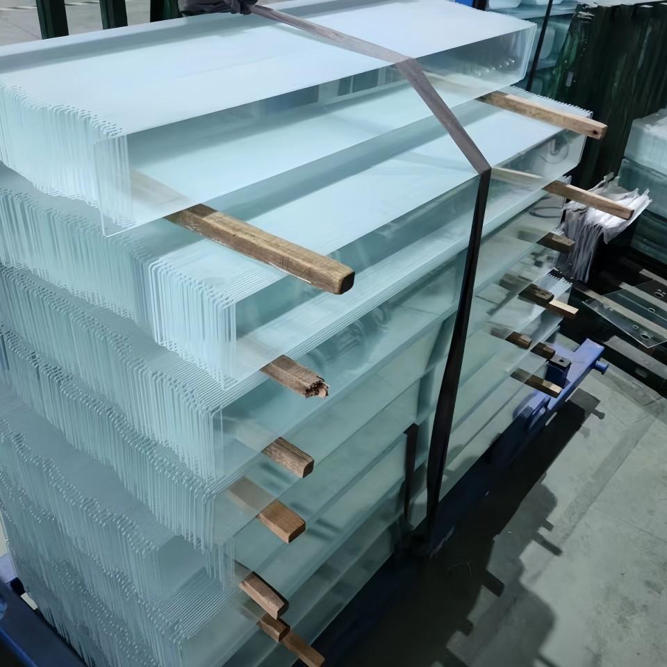
What are the auxiliary raw materials of glass?
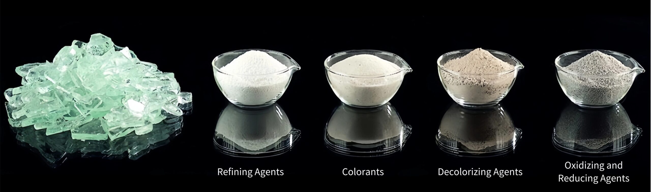
| Category | Material | Characteristics |
|---|---|---|
| Colorants (Ionic) | Iron Compounds | FeO (Black Powder) - Produces blue-green glass; Fe₂O₃ (Red-brown Powder) - Produces yellow-green glass |
| Manganese Compounds | MnO₂ (Black Powder) - Produces light yellow glass; KMnO₄ (Gray-purple Crystals) - Produces reddish-purple glass | |
| Colorants (Colloidal) | Gold Compounds | AuCl₃ (Dissolved in aqua regia) - Produces rose, ruby, or red-gold glass based on concentration |
| Silver Compounds | AgNO₃ (Colorless Crystals) - Produces yellow glass when heated | |
| Flux Agents | Fluorides | Fluorspar (CaF₂) - Improves melting efficiency when combined with Al₂O₃ |
| Decolorizing Agents | Oxidants | NaNO₃, KNO₃ - Remove unwanted coloration caused by iron and other impurities |
| Reducing Agents | Carbon-Based | Charcoal, Coke, Wood Powder - Act as reducers in glass manufacturing |
Cullet
What are the steps for broken glass processing?
Washing:
Cullet passes through equipment such as hoppers, belt conveyors, rotary drum washers, and sedimentation tanks to remove dirt and sand. This process cleans the cullet, making it easier to sort and recycle.
Grading:
Cullet is classified using belt conveyors and vibrating screens. Large fragments are manually sorted based on types, such as float glass, patterned glass, quartz glass, or colored glass. Flat glass can be reused directly, while patterned glass, having a different composition, requires chemical analysis and formula adjustments before being incorporated into the batch. Quartz glass must be crushed to pass a 20-mesh sieve, and colored glass is sorted by color for selective reuse depending on production needs.
Crushing:
Large cullet fragments are not suitable for batch uniformity and can cause melting issues, while excessively fine cullet increases gas adsorption, hindering the refining process. The ideal cullet size ranges from 20–40 mm. The crushing system includes roller crushers, elevators, electromagnetic feeders, drum screens, and dust collectors. Coarse particles are reprocessed through crushing cycles, while properly sized cullet is sent to storage for composition analysis before use in the batch formulation.
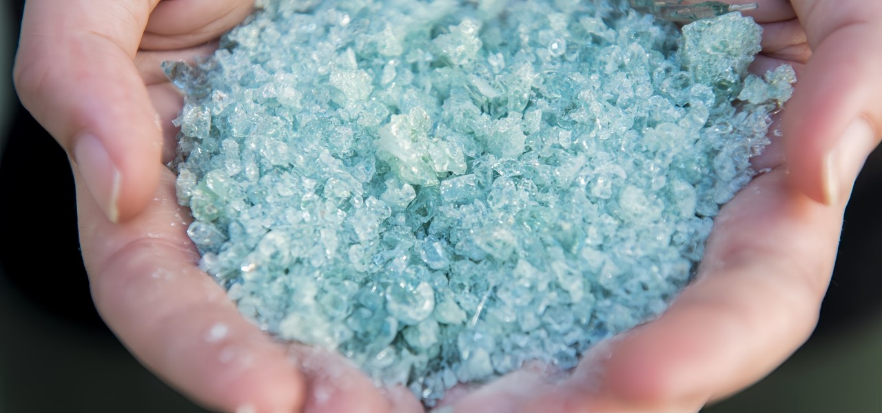
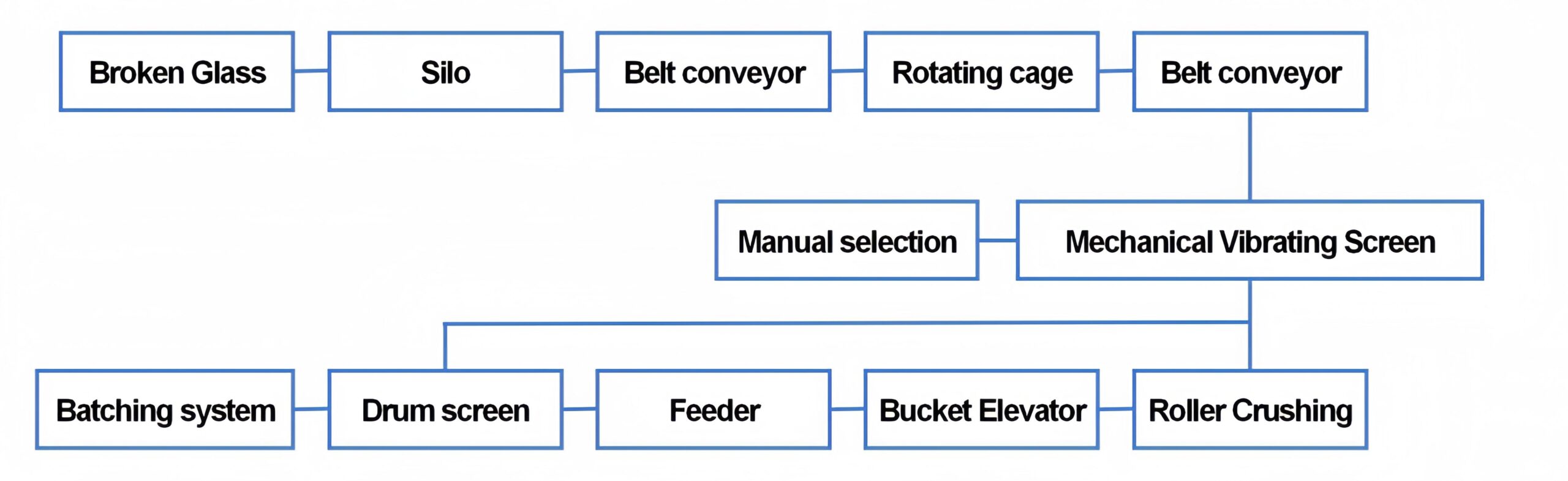
Process flow of broken glass processing system
Precautions when using cullet
② Add oxidants and decolorizers appropriately. When the cullet is remelted, some of its components will undergo thermal decomposition and release oxygen, making it have reducing properties. For colored glass based on variable valence elements, it will cause color changes, and for colorless glass, the color of the glass will become darker due to the conversion of Fe₂O₃ into FeO. Therefore, oxidants and decolorizers should be added appropriately.
③ Replenish clarifiers. Cullet contains a small amount of chemically combined gas, which produces small bubbles equivalent to secondary bubbles during remelting. Therefore, when adding cullet, clarifiers should be added.
④ The appropriate particle size of the cullet should be determined. When the particle size of the cullet is less than 0.25mm and greater than 2mm, both have good effects on melting. In production, 2-20mm particle size is generally used.
⑤ Remove impurities. The chemical composition of the cullet should be the same as the glass in the kiln, otherwise, the impurities in the cullet must be screened, washed,d and removed before use.
⑥ The amount of the cullet should be stable. Generally, the amount of cullet used in float glass is equal to 20%~30% of the total weight of the raw materials.
What is the production process of clear float glass?
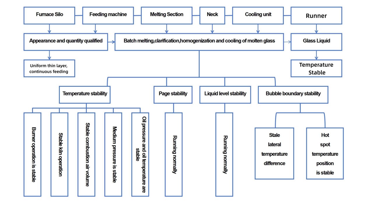
What is the float glass melting process?
| Physical Reactions | Chemical Reactions | Physicochemical Reactions |
|---|---|---|
| Heating of raw materials | Decomposition of carbonates | Formation of eutectic mixtures |
| Drying of raw materials | Decomposition of sulfates | Solubility in solids and liquid interactions |
| Melting of individual components | Decomposition of nitrates | Interactions between glass melt, furnace gases, and bubbles |
| Phase transformation | Decomposition of chemically bound water | Interactions between glass melt and refractory materials |
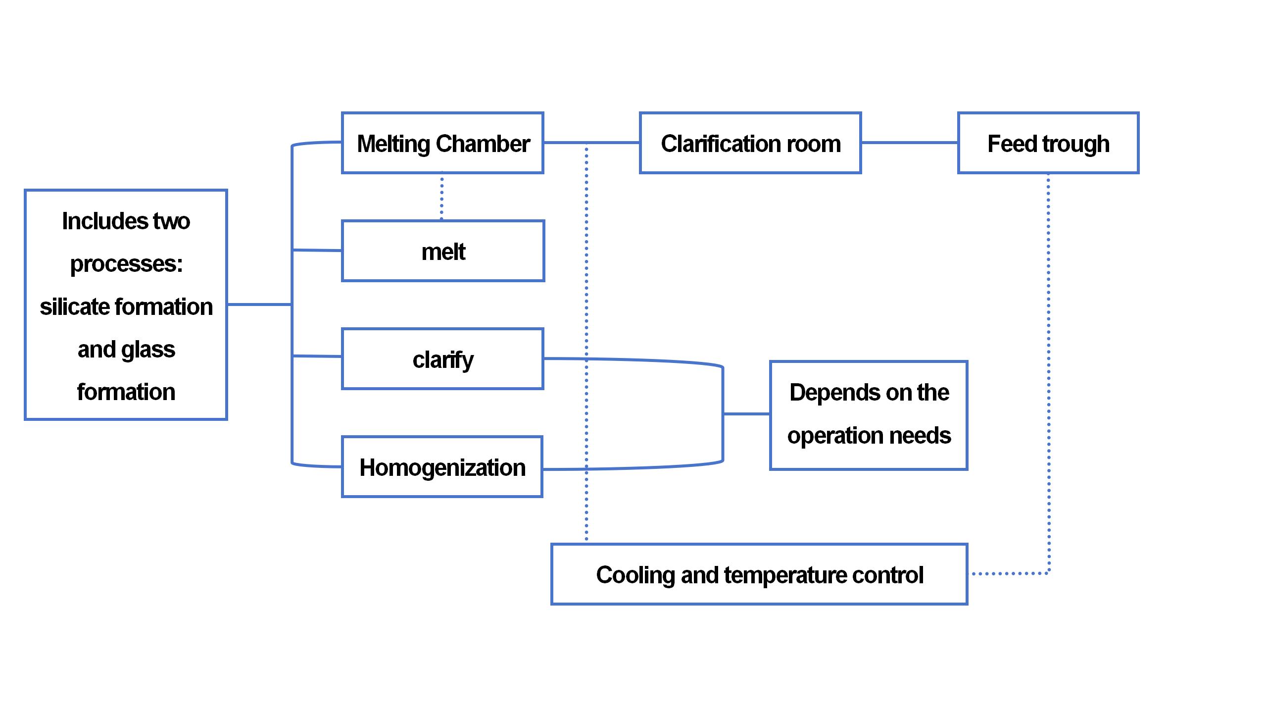
What are the classifications of melting process stages?
Formation of Silicates (800°C – 1000°C):
The result is an opaque sintered material composed primarily of silicates and silica.
Formation of Glass Liquid (>1200°C):
This stage culminates in the formation of an uneven, bubbly glass liquid that is not yet transparent.
Clarification Stage (1400°C – 1500°C):
Trapped air bubbles expand and escape due to reduced viscosity, leading to a clearer glass with some visible streaks remaining.
Homogenization Stage:
Extended high-temperature exposure allows for even composition and temperature distribution through convection and diffusion.
This stage concludes just below the clarification temperature, ensuring uniformity in the glass liquid.
Cooling Stage (1100°C – 1050°C):
Proper cooling prevents stress and ensures the glass can be shaped without distortion or breakage.
What factors affect float glass melting?
- Chemical composition of batch materials: The chemical composition of raw materials has a decisive influence on the melting rate, and different temperatures are required according to different formulas. The higher the ratio of total alkali metal oxides to SiO2 and Al2O3, the higher the solubility.
- Raw material characteristics: The nature and type of raw materials significantly affect melting, including particle size, shape, local refractoriness, gas content, and composition. To introduce the same oxides, the most favorable mineral and chemical raw materials for melting are selected.
- Mixing of batch materials: The uniformity of batch preparation is a key process indicator that directly affects the quality and melting rate of glass. Ensure that the batch stratification phenomenon is fully mixed and maintained uniformly distributed.
- Feeding method: Different feeding methods affect the melting rate, temperature distribution in the melting zone, and surface stability, and ultimately affect the output and quality of glass. The thin layer feeding method (material layer thickness is controlled within 50mm) promotes uniform distribution of components and accelerates the reaction.
- Melting temperature range: Higher temperatures can increase the intensity of the reaction, accelerate the fusion of batch particles, and accelerate the formation of glass liquid. In the range of 1400-1500℃, every 1℃ increase in melting temperature can increase the melting rate by 2%, which is an effective strategy to increase production capacity.
- Furnace pressure, atmosphere: The stability of the furnace pressure and atmosphere affects the melting efficiency and product quality.
- Refractory and fuel quality: The condition of the furnace lining and the type/quality of the heating fuel directly affect the melting performance.
- Furnace structure and auxiliary equipment: Design features such as the configuration of the furnace body and auxiliary facilities such as stirrers can affect the temperature distribution and material movement in the furnace.
- Automation level: A higher degree of automation improves the accuracy of process control and the efficiency of monitoring and adjusting key parameters during glass melting.
What is float glass forming process?
Forming mechanism
Glass Liquid Floating Height on the Tin Liquid Surface
The floating height h₁ and immersion depth h₂ of the glass liquid can be expressed using the equation :
h₁ = (dg – dt) / dg * H
Where
Dg and dt are the densities of the glass and tin liquid, respectively.
H is the free thickness of the glass liquid on the surface of the tin liquid.
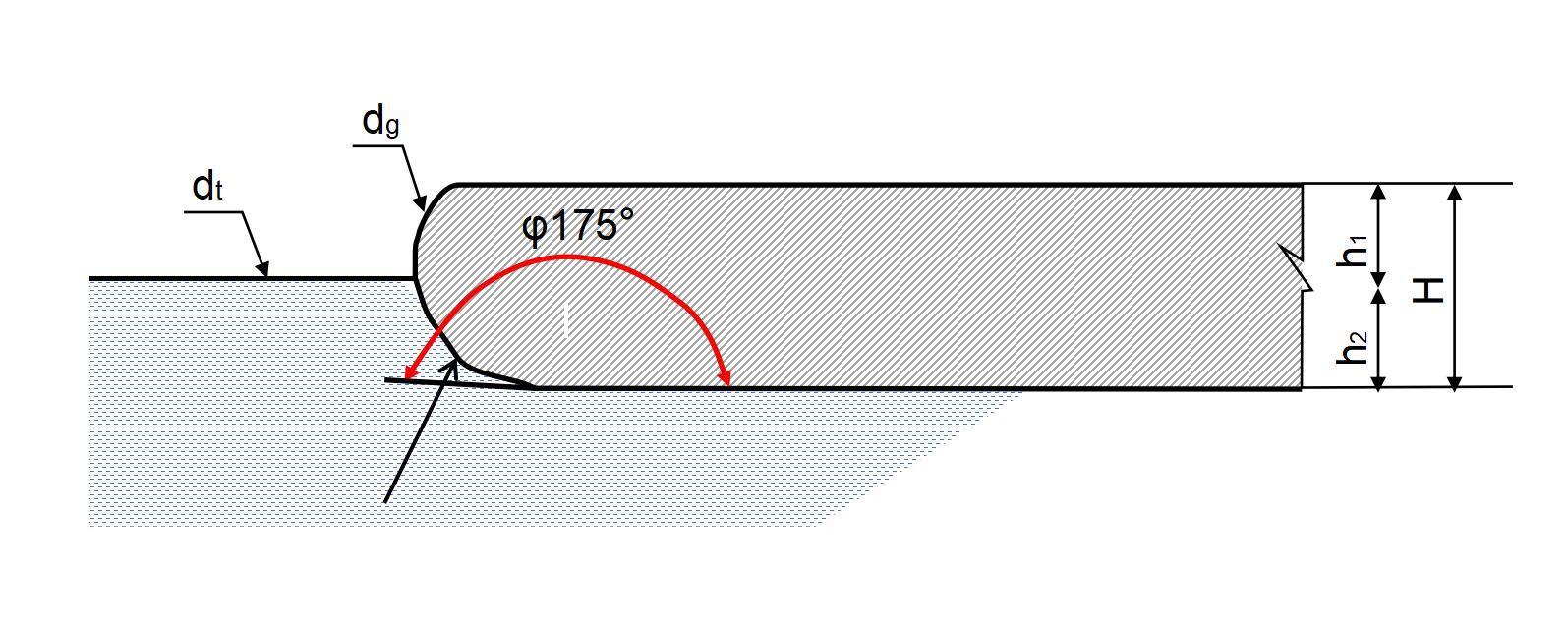
Schematic diagram of the floating height of glass liquid on the surface of tin liquid
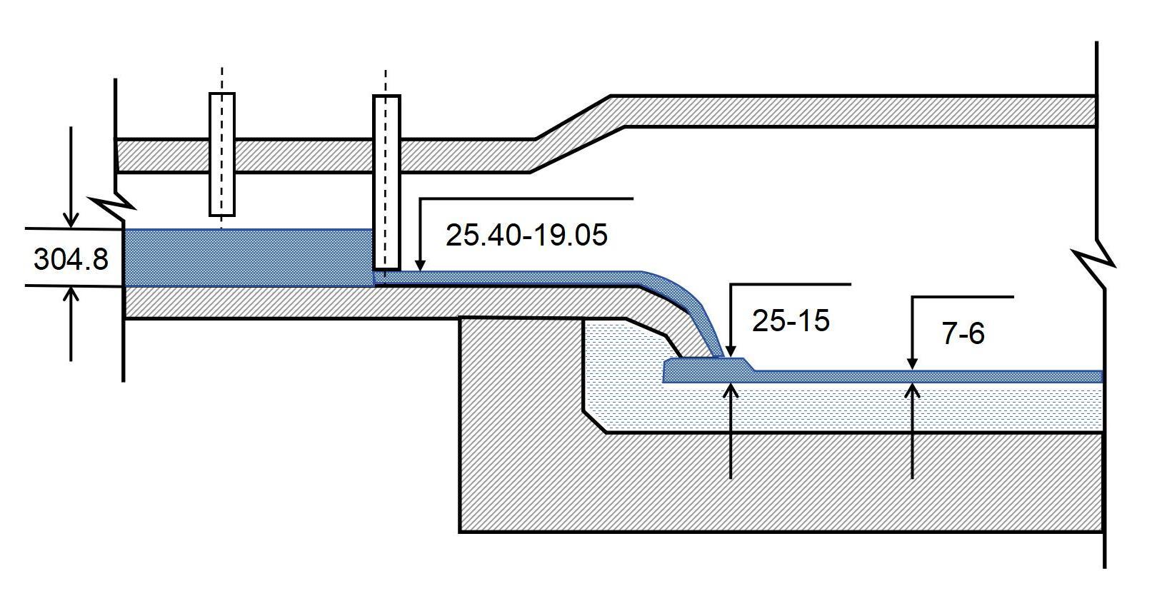
Thickness of glass liquid at the inlet of tin bath (unit: mm)
Free Thickness of Float Glass
σg, σt, σgt, dg, dt and g (gravitational acceleration)
The relationship between the surface tension and density of glass, tin, and protective gas at various temperatures is shown in Table. For instance, at 850°C, the density of the glass liquid is 2493 kg/m³, and the surface tension is 0.5113 N/m.
By substituting the values from the Table into the equation the equilibrium thickness of the glass ribbon can be calculated. At 850°C, the balance thickness of the glass ribbon is approximately 7 mm, which is consistent with actual measurements.
| Temperature (°C) | Density of Glass Liquid (dg) [kg/m³] | Density of Tin Liquid (d) [kg/m³] | Interfacial Tension (a) [N/m²] | N-H |
|---|---|---|---|---|
| 850°C | 2493 | 6560 | 0.5113 | 0.3614 |
| 1000°C | 2490 | 6518 | 0.4905 | 0.3335 |
Polishing Time of Glass on the Tin Liquid Surface
When the glass liquid flows from the channel into the tin bath, the difference in height between the channel surface and the tin liquid surface, along with the uneven flow velocity, creates a sinusoidal wave pattern. As the liquid spreads laterally and drifts forward, the sinusoidal pattern gradually weakens, as shown in Figure. At high temperatures, the glass liquid’s surface tension helps it flatten, resulting in a polished surface. The time required for this polishing process is referred to as the polishing time, and it is an important technical parameter for designing the length and width of the tin bath.
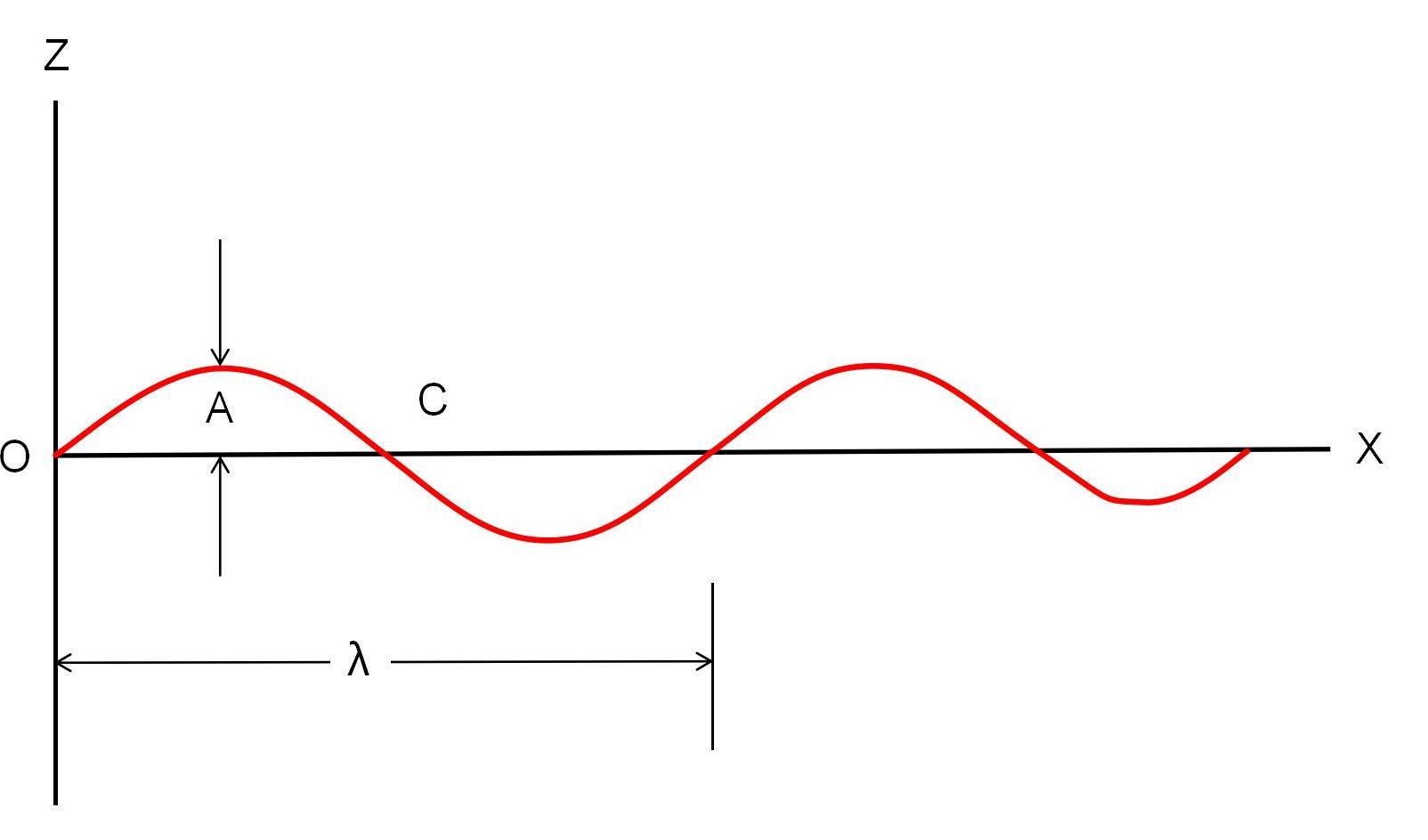
Pressure on the Glass Liquid
P = σ (1 / R₁ + 1 / R₂)
where R₁ and R₂ are the radii of curvature of the glass liquid surface in the length and width directions. The surface tension plays a major role in the polishing process, and the critical value of surface tension should not be lower than the static pressure to achieve a smooth, polished surface.
Estimation of Polishing Time
λo = 2.4 cm
v = 3.5 × 10⁻² cm/s
By using the formula t = λ / v, the estimated polishing time is approximately 68.5 seconds. In practice, the glass liquid remains in the polishing zone for about 1 minute to achieve a bright, smooth surface, which aligns well with the theoretical estimation.
Factors affecting forming quality
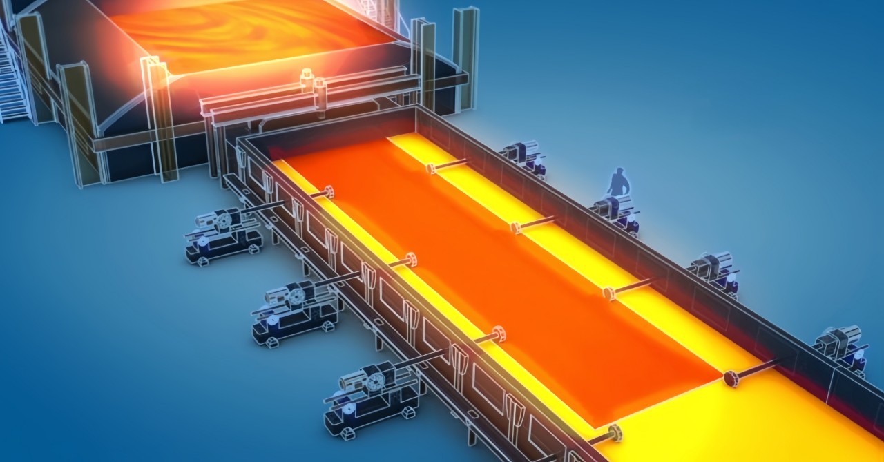
Tin Bath Temperature Regime
The tin bath temperature regime refers to the temperature distribution along the length of the tin bath. It forms the basis of the forming process and plays a critical role in the spreading, polishing, cooling, and solidification of the glass liquid. It also affects the drawing speed of the glass ribbon, the types and specifications of the glass, as well as production yield and quality. The following points outline the impact of temperature on forming, with a focus on variations in the flow channel temperature:
- Excessively High Flow Channel Temperature: When the flow channel temperature is too high, the viscosity of the glass liquid decreases, causing it to spread out more when entering the tin bath. This results in a glass ribbon that is too thin and wide, leading to issues such as edge sticking and full bath overflow. Moreover, forming becomes difficult at the edge drawing machine.
- Excessively Low Flow Channel Temperature: When the flow channel temperature is too low, the viscosity of the glass liquid increases, which affects the conditions for spreading and polishing. This negatively impacts the surface quality of the glass and may lead to edge separation and glass breakage. It also causes difficulties in drawing the glass to the desired thickness or accumulation.
- Temperature Fluctuations: Fluctuating flow channel temperatures cause instability in the width of the glass ribbon. The thickness of the glass ribbon will vary accordingly, leading to issues such as edge separation and edge sticking.
- Uneven Flow Channel Temperature: If the temperature is uneven along the flow channel, the viscosity of the glass will vary across the width of the ribbon. This can result in defects such as “streaks” on the glass product due to uneven spreading and cooling.
Tin Bath Pressure Control
- Temperature Control – The tin bath is a high-temperature environment, making the protective gas highly sensitive to temperature fluctuations. Temperature changes directly impact pressure stability.
- Protective Gas Volume and Pressure – The tin bath chamber must be filled with protective gas. If the gas volume is insufficient, the bath may enter a negative pressure state. For tin baths with a production capacity of 300–400 tons per day, the standard protective gas flow rate is 1100–1400 m³/h. The gas volume is directly proportional to its pressure; if the pressure drops, the gas supply decreases, leading to a negative pressure condition. The typical outlet pressure of the protective gas is maintained at around 2000 Pa.
- Sealing Conditions – Proper sealing is crucial for maintaining pressure stability. A well-sealed tin bath minimizes gas leakage, ensuring a stable protective atmosphere.
Variations in Furnace Operation
Glass Level Fluctuations – Variations in the molten glass level affect the flow rate entering the tin bath, leading to width changes in the glass ribbon. This can cause edge defects such as overcoating or edge detachment. If the level fluctuation is severe, it alters the glass flow behavior, leading to temperature and compositional inconsistencies that create streaks in the final product.
Furnace Pressure Fluctuations – Changes in furnace pressure can alter the flow rate in the forehearth and affect the width of the glass ribbon, increasing the risk of edge defects or an overfilled tin bath.
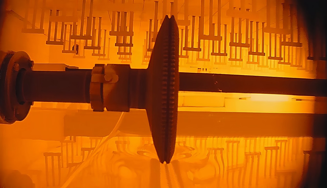
Tin Bath Atmosphere Control
Currently, a protective gas mixture of N₂ and H₂ is commonly used in tin baths. The typical composition is 90%–97% N₂ and 3%–10% H₂, with an oxygen content not exceeding 5 cm³/m³ (ppm). If the protective gas quality is poor or contains impurities, it can increase contamination of the molten tin. If the gas supply is insufficient, the pressure in the tin bath may drop too low, allowing external air to enter and oxidize the tin. Both scenarios can lead to glass defects such as tin adhesion and scratches. Additionally, pressure fluctuations may cause “tin drops” to appear.
Tin Surface Level and Depth
Theoretically, the tin surface should be as level as possible with the edge of the tin bath. However, to prevent tin overflow and avoid tin being carried out by the moving glass ribbon, the tin surface is typically maintained about 20 mm below the edge. This requires the tin bath’s edges to be precisely leveled during design, construction, and even after the heating process. Uneven edges or gaps can lead to tin overflow. Additionally, the steel casing at the tin bath’s exit must be effectively cooled to prevent it from melting due to prolonged contact with molten tin.
The tin depth inside the bath generally ranges between 50 and 100 mm. Two common depth configurations are used:
- Uniform Depth – The tin depth remains the same from the front to the end of the bath, typically between 100 and 110 mm. This flat-bottom design is simple and easy to construct but requires a larger volume of tin.
- Stepped Depth – This design incorporates bottom dams to control tin flow according to the glass-forming requirements. Although more complex, it reduces the amount of tin required and minimizes variations in tin depth across different sections of the bath. Table 4-9 lists the tin depths at various positions in a 49-meter-long tin bath.
Thin Glass Formation
Glass with a thickness lower than its natural equilibrium thickness is classified as thin glass. Producing such glass requires external forces from edge pullers and the main drive rollers.
- Increasing the pulling speed of the main drive rollers accelerates the movement of particles within the glass ribbon, increasing tension and thinning the glass.
- Edge pullers apply lateral force to the glass ribbon to counteract the shrinkage force in the width direction, ensuring uniform thickness and preventing defects.
Currently, there are two main methods for producing thin glass: high-temperature thinning and low-temperature thinning, as shown in Figure.
In high-temperature thinning (1050°C), the width and thickness change follow the POQ curve in Figure 4-29.
In low-temperature thinning (850°C), the width and thickness change follow the PBF curve.
For example, if the original glass ribbon is at point P with a width of 5m and a thickness of 7mm:
When using the high-temperature method, pulling the width to 2.5m results in a thickness of 6mm (point O).
When using the low-temperature method, pulling to the same width results in a thickness of 3mm (point F).
Similarly, if the target thickness is 4mm:
The high-temperature method results in a width of 0.75m (point Q).
The low-temperature method results in a width of 3m (point B).
This demonstrates that the low-temperature method can produce thinner glass, making it the preferred method in modern glass manufacturing.
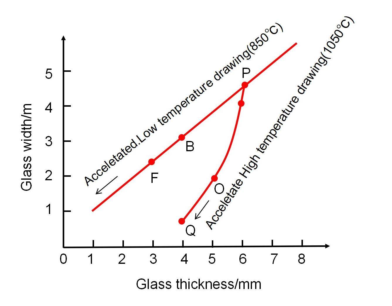
High and low temperature thinning curves
Low-Temperature Thinning Method
(1) Rapid Cooling Method
In this method, the glass ribbon is quickly cooled to around 700°C (viscosity ~10 Pa·s) after leaving the polishing zone. It then enters a reheating zone, where it is heated to 850°C (viscosity ~10⁰ Pa·s) before being thinned by increasing the pulling speed.
Advantages:
The rapid cooling prevents deformation, maintaining the quality of the polished surface.
It achieves effective thinning results.
Disadvantages:
The rapid cooling and reheating cycles cause uneven temperature distribution, leading to possible thickness variations.
The additional reheating process increases energy consumption and production costs.
(2) Gradual Cooling Method
The gradual cooling method is the most commonly used process for producing thin glass. Unlike the rapid cooling method, it does not involve a sudden cooling zone or reheating zone. Instead, the temperature decreases gradually, avoiding thermal shock and ensuring a uniform temperature across the glass ribbon. This method has minimal impact on glass quality, is easy to operate, and consumes less energy.
The gradual cooling process involves four zones:
Spreading (Polishing) Zone – 1055–996°C (viscosity: 10²–10¹² Pa·s)
Ensures that the molten glass entering the tin bath spreads evenly and achieves a natural equilibrium thickness.
Gradual Cooling Zone – 996–883°C (viscosity: 10³.²–10 Pa·s)
The glass ribbon is stretched by the main drive rollers.
Edge pullers are used to control width shrinkage, ensuring that the reduction mainly affects thickness.
Forming Zone – 883–769°C (viscosity: 10⁴.²⁵–10⁵.⁵⁷ Pa·s)
Several pairs of edge pullers apply both lateral and longitudinal forces, further stretching the glass to achieve the desired thinness.
Cooling Zone – 769–600°C (viscosity: 10⁵.⁷⁵–10⁵.⁵⁷ Pa·s)
The glass ribbon is no longer thinned but is gradually cooled.
The temperature at the tin bath exit is approximately 600°C.
Key Considerations for Thin Glass Production
Thin Glass Edge Puller Parameters
| Item | 1# | 2# | 3# | 4# | 5# | 6# |
|---|---|---|---|---|---|---|
| Edge Puller Speed (m/h) | 960 | 900 | 870 | 880 | 860 | 790 |
| Rod Outer Clearance (S) (mm) | 1160 | 1120 | 1160 | 1130 | 1050 | 1010 |
| Rod Outer Clearance (N) (mm) | 7.5 | 7.5 | 7.5 | 5 | 6 | 5.5 |
Thick glass forming
Edge Puller Method
Advantages:
Requires no additional auxiliary equipment
Simple operation and flexible thickness adjustments
Disadvantages:
Limited thickness range
Difficult to control during production
Highly sensitive to temperature fluctuations, which may lead to uneven thickening or edge adhesion defects
Deep teeth marks caused by the puller heads can distort the glass edges, reducing the pulling efficiency
This method is suitable for producing glass with thicknesses ranging from 8 to 19 mm.
Example: 12mm Thick Glass Production
Production output: 470 t/d
Main drive speed: 185 m/h
Original glass width: 3550 mm
Final glass width: 3050 mm
Inner tooth distance: 3210 mm
Flow channel temperature: 1100°C
Tin bath exit temperature: (595 ± 5)°C
Final average thickness: ≤ 11.90 mm
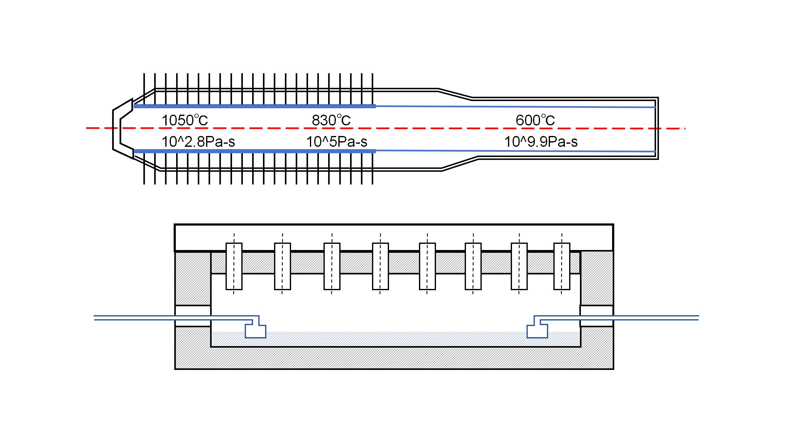
Graphite retaining wall method
Fender Wall Method
The fender wall method (FS method) is a proprietary technology developed by Pilkington Glass (UK). This method involves installing long graphite water-cooled fender walls in the high-temperature zone of the tin bath, where the glass spreads and accumulates to the required thickness.
Key technical challenges:
- The graphite must not stick to the molten glass at high temperatures.
- Controlling the glass flow rate and thickness precisely.
- The complex structure of the fender wall requires strict installation positioning and precise water-cooling control
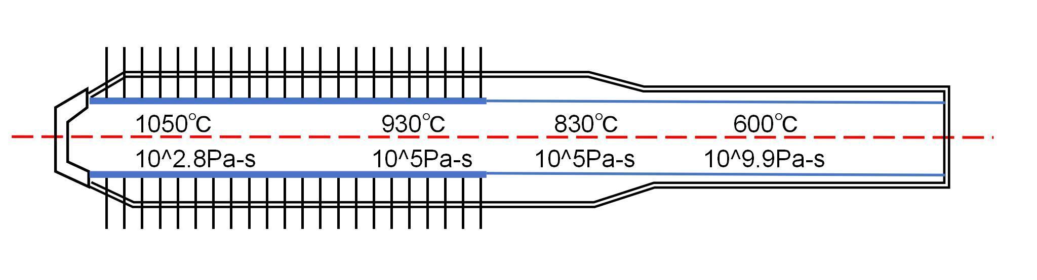
Schematic diagram of retaining wall edge pulling machine method
By using graphite water-cooled fender walls, the lateral flow of the molten glass is restricted within the tin bath. This accumulation process is further adjusted using linear motors, cooling water systems, and tin bath electrical heating to control thickness and ribbon width.
Advantages:
Produces glass with excellent flatness and optical quality.
Suitable for manufacturing glass with thicknesses ≥ 15 mm.
Disadvantages:
Since the glass remains in the tin bath for an extended period, crystallization (devitrification) may occur.
Glass residue tends to accumulate at the fender wall junctions, leading to crystallization.
Regular cleaning is required, preventing long-term continuous production.
Contact Us
Your feedback fuels our growth, and your questions drive our solutions.
We value your feedback, inquiries, and suggestions. Please feel free to get in touch with us
General inquiries
Please contact us via sales@bo-glass.com, and we will reply to you as soon as possible.
Interested to work with us
Drop your resume at info@bo-glass.com
and we will get back to you shortly.
We uses the contact information you provide to us to contact you about our relevent content, products, and services.