
Aircraft Exterior & Cabin Lighting Glass
Glass for aircraft position, anti-collision, landing, taxi, recognition, emergency, and cabin lighting assemblies.
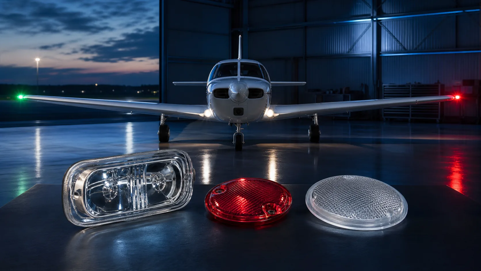
Aircraft lighting application and acceptance guide
Start with the installed lighting function. The same transparent material can require very different optical, environmental and safety evidence depending on its location and complete-light configuration.
| Application | Typical glass component | Core function | Primary risks | Complete-unit acceptance |
|---|---|---|---|---|
| Position light | Colored lens, cover or filter | Color and coverage sectors | Spectral shift, weak sectors and installation obstruction | Chromaticity, coverage angle and intensity |
| Anti-collision light | Dome or clear/red cover | Flashing output and broad coverage | Heat, vibration and internal reflection | Effective intensity, flash frequency and coverage |
| Landing or taxi light | Protective window or beam lens | High transmission and beam protection | Rain erosion, particles, thermal gradients and scatter | Beam, transmission and performance after environmental exposure |
| Inspection or service light | Window or projector lens | Localized illumination | Fluids, vibration and cleaning | Illuminated area and environmental durability |
| Cabin reading light | Lens or diffuser | Task beam, shielding and passenger comfort | LED hot spots, neighboring-seat spill and glare | Illuminance, uniformity and viewing-position assessment |
| Emergency or exit light | Printed cover, filter or diffuser | Legend clarity and emergency visibility | Low voltage, breakage, combustible layers and retention | Readability and retained function under emergency power |
Before requesting samples, identify the aircraft location, light function, approved or proposed part number, source type and operating point, clear aperture, viewing envelope, mounting datums, seals, adjacent structure and environmental categories. For a replacement optic, also provide the equipment manufacturer, model, drawing revision, representative service samples and the organization authorized to approve a change. These inputs prevent a visually similar glass part from being treated as technically interchangeable.
Acceptance should follow the failure mechanism. A colored position-light lens needs source-matched spectral and dimensional evidence before complete-light color, intensity and sector testing. A landing-light window needs surface, edge and coating controls before erosion, thermal and post-exposure beam checks. A cabin diffuser needs transmission, haze, texture and appearance limits before installed illuminance, uniformity and glare assessment. Record the configuration used for every result so later changes to the source, optic, coating, seal or housing can be reviewed against the approved baseline.
Aircraft Exterior Lighting Glass
Aircraft exterior lights combine optical performance with a fast-changing environment. A landing-light cover may move from cold soak to intense local heating, while navigation and anti-collision lenses must retain color and visibility through vibration, rain, ultraviolet exposure, cleaning, and aerodynamic airflow. This chapter explains how the cover or lens becomes part of the light rather than merely a transparent barrier in front of it.
Which aircraft exterior lights use glass lenses or covers?
Glass can be used in position and anti-collision lights, landing and taxi lights, runway-turnoff lights, inspection or service lights, logo lights and special-purpose illumination. The part may be a protective window, colored cover, filter, molded lens, diffuser or dome. Polymers and hybrid materials remain common where low mass, complex shape or impact behavior is more important.
Select glass when scratch resistance, thermal stability, chemical durability, optical precision, stable color or long-term clarity justifies its density and edge sensitivity. The RFQ should identify the exact installation, certification basis, source, viewing envelope, mounting, environmental qualification and service concept. A material name or generic “aircraft lens” description cannot define the required optical or mechanical duty.
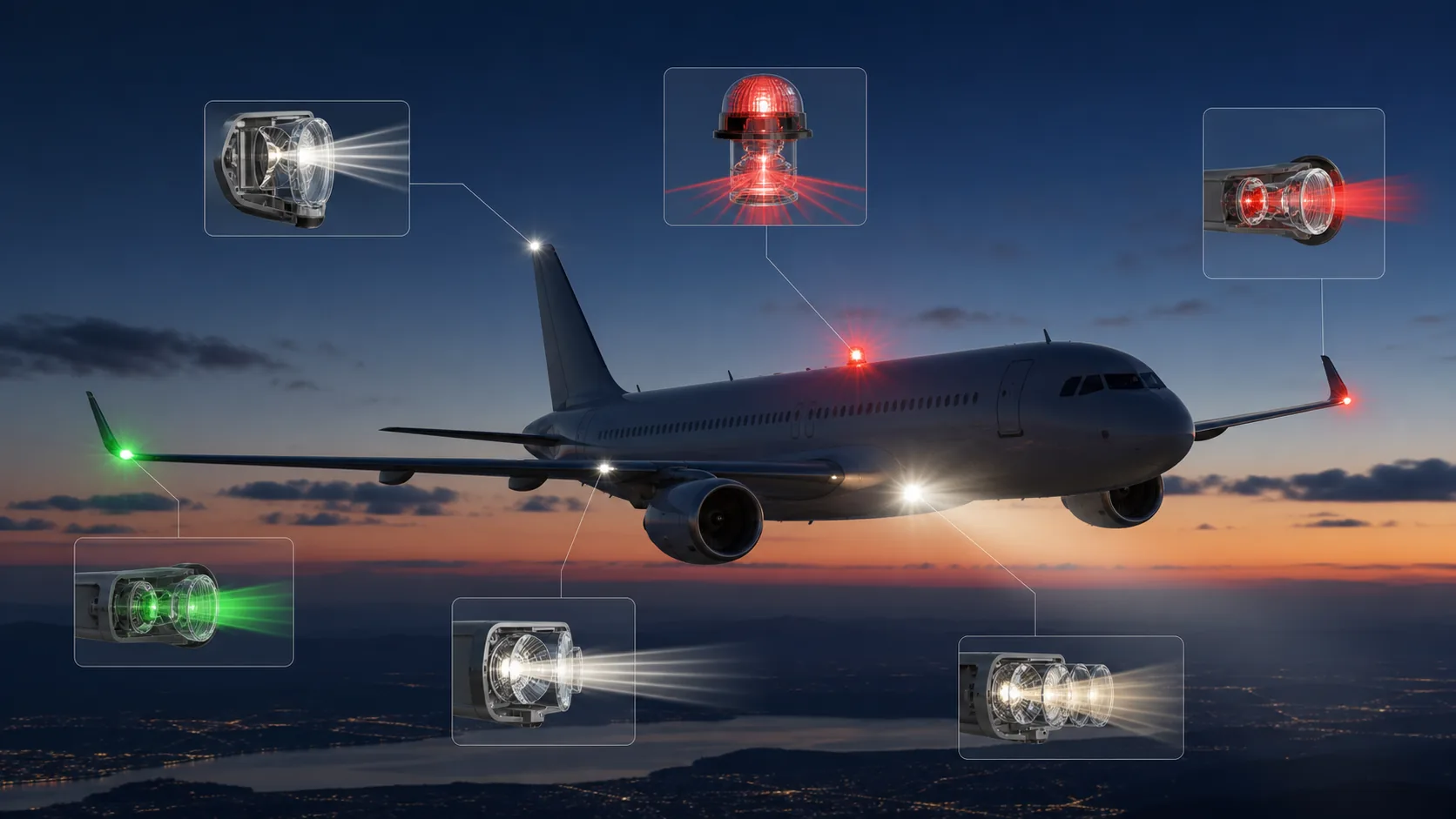
Signal lights: position and anti-collision optics
Position lights identify aircraft orientation through controlled red, green and white signals and fields of coverage. Lens geometry, spectral transmission, source position and aircraft structure can all affect sector boundaries, chromaticity and intensity. Curved covers change incidence angle around the source; wall-thickness variation, mold seams and mounting flanges can create weak or obstructed sectors.
FAA AC 20-30B provides an active means of compliance for applicable position- and anti-collision-light installations. FAA AC 20-74 provides measurement guidance for intensity, coverage and color. Their applicability depends on the aircraft certification basis; the production-representative installed system—not the loose glass—supplies the final compliance evidence.
Anti-collision covers must preserve broad controlled coverage and effective output during repeated flashes while resisting source heat, vibration, weather and internal reflections. LEDs introduce multiple emitters and narrow spectra; discharge or legacy sources can introduce different thermal and spectral conditions. Specify source, color, geometry, wall thickness, optical surface zones and environmental exposure together, then verify flash behavior, coverage, intensity and color on the configured light.
Landing-light covers and erosion exposure
The two components may both be transparent exterior parts, but their priorities differ:
- Landing-light cover: protects a concentrated white beam. Transmission, reflection, rain and particle erosion, thermal gradients, contamination, wedge, and forward scatter directly affect useful range.
- Position-light lens: communicates orientation through color and angular sectors. Spectral stability, source-filter matching, sector boundaries, and recognition from multiple directions dominate.
Shared checks. Both designs need compatible seals, protected edges, controlled installation stress, fluid and cleaning durability, and qualification selected by the equipment OEM and aircraft integrator. Nose, wing-root, landing-gear, and fuselage locations can create very different vibration, rain, debris, and pressure conditions.
A landing-light cover is driven by high flux, erosion, thermal gradients, and forward visibility, while a position-light lens is driven more strongly by color, sector control, and recognition from multiple angles.
At aircraft speed, rain and airborne particles strike the exposed surface with repeated energy.
Dirt and runway debris add abrasion, while cleaning can extend surface damage. The result can be pits, scratches, coating loss, haze, and increased scatter. Leading-edge or forward-facing installations are more severe than sheltered locations.
Glass generally resists scratching better than many uncoated polymers, but edges, coatings, and local impacts still need protection. A hard coating on another substrate may perform well initially yet erode differently. The choice should be based on representative angle, speed, droplet or particle conditions, exposure duration, and optical acceptance—not a generic hardness value.
Evaluate transmission, scatter, beam shape, and visual condition after exposure. Consider replaceable outer windows where lifecycle economics justify them. Avoid placing fragile coating transitions in the main impact zone. Maintenance instructions should prohibit abrasive wiping of dry particulate. If field units haze prematurely, analyze the damage morphology and route rather than assuming material aging.
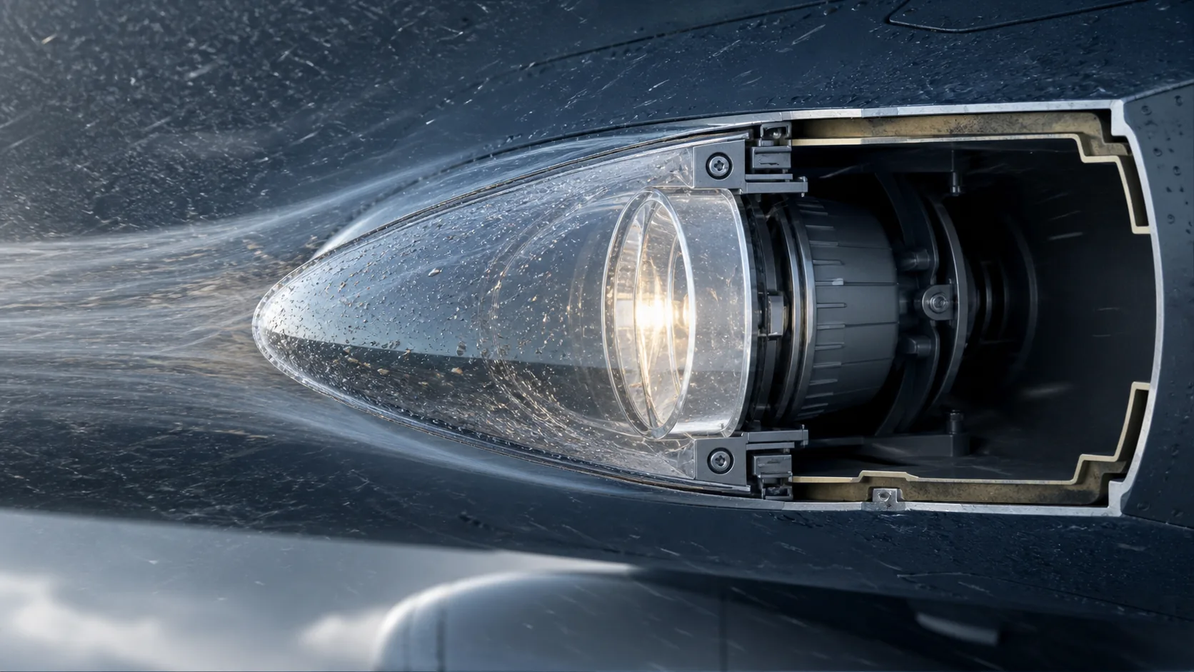
Thermal, fluid and vibration exposure
Exterior-light durability depends on the mounted assembly and actual installation. Use component tests to screen material, coating and edge risks, then verify the production-representative light under the selected program conditions.
| Exposure | Glass or assembly risk | Component screening | Complete-equipment verification |
|---|---|---|---|
| Thermal gradient | Stress, cracking and optical shift | Material, thickness, edges and coefficient of thermal expansion | Cold start, source operation and rain or water transition |
| Vibration and shock | Looseness, edge contact and alignment change | Mounting interface and surface-defect controls | Production-state fixture vibration and shock testing |
| Aviation fluids | Coating, ink, adhesive and seal degradation | Exposure to the actual fluid by immersion, spray or wiping as applicable | Leakage, optical and assembly inspection after exposure |
| Rain erosion and particles | Pitting, haze and forward scatter | Representative surface and coating exposure | Complete beam check after exposure |
| Cleaning | Scratches, coating wear and residue | Approved cleaner and wiping cycles | Appearance and optical-output check after cleaning |
Most exposure failures are interface failures rather than bulk-glass failures. A hard window can still crack when a retainer creates point contact, a seal swells in fluid, an adhesive softens, or a hot source produces a steep local gradient. Review the load path from housing through gasket or bond line into the finished edge, and test with production tolerances that represent the most demanding permitted fit. Coatings, masks and printed areas should be present when they can affect heat absorption, fluid resistance or retention.
Define pre- and post-exposure acceptance before testing: visual defect zones, transmission or haze, leakage, torque or retention, alignment, color and complete beam or photometric performance as applicable. Record the test category, specimen build, mounting orientation, operating state and allowed recovery time. This creates evidence that can be compared after a supplier, material, coating or process change instead of relying on a pass/fail label with no configuration context.
Record specimen geometry, mounting, fluid or particle conditions, temperature, duration and acceptance method whenever durability is claimed. RTCA DO-160G provides environmental test procedures for airborne equipment, but the program selects the applicable sections, categories, fluids and configured specimen. A coupon result does not transfer complete-light qualification to the glass.
Strengthening and tempering choices
Strengthening is one design option, not a substitute for protected edges, controlled mounting and complete-equipment qualification.
| Route | When it can fit | Primary cautions |
|---|---|---|
| Chemical strengthening | Compatible thin or complex glass that must retain optical form while gaining handling or flexural margin | Glass chemistry, surface compression, layer depth, edge preparation and all processing after strengthening |
| Thermal tempering | Glass thickness and geometry permit rapid, sufficiently uniform cooling | Shape change, optical distortion, roller wave, dimensions and completion of cutting or drilling beforehand |
| Unstrengthened glass | Loads are modest and the installation protects surfaces and edges adequately | Actual flaw population, handling, retention and mounted stress still require control |
The final choice must be confirmed on the finished geometry with its edges, coatings, printing, installation and complete-light test evidence. See Aerospace Glass Materials & Manufacturing for detailed process selection and inspection considerations.
Cabin and Emergency Lighting
Cabin and emergency-lighting glass is a balance of human factors and engineering constraints. Diffusion can improve comfort and visual uniformity, but it can also reduce useful intensity; thinner components can save weight, but mounting and impact behavior then become more important. This chapter explains how appearance, emergency visibility, cleaning, flammability boundaries, service life, and replaceability influence the component choice.
What glass components are used in aircraft cabin lighting?
Cabin applications can include reading-light lenses, decorative diffusers, emergency and exit-sign covers, galley and lavatory light windows, service lights, and illuminated control or indicator covers. Glass may be chosen for scratch resistance, heat stability, premium appearance, cleanability, thin optical features, or long-term color stability. Polymers remain common where low mass and impact behavior dominate.
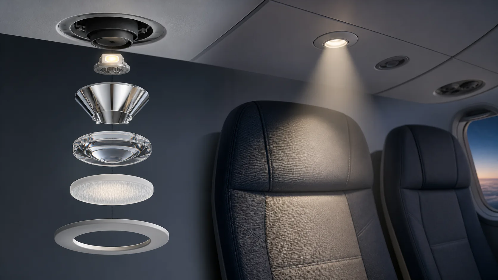
The optical task ranges from a focused reading beam to broad uniform mood light. Glass can diffuse LED point sources, hide color mixing, shape a spot, protect a printed legend, or provide a touch surface. It must integrate with seat monuments, passenger service units, overhead panels, or sidewall architecture without creating sharp edges, glare, or rattling. Define the certification and cabin-safety context with the aircraft integrator. Flammability, smoke and toxicity policies, head-impact zones, retention under emergency loads, and evacuation visibility can influence material and mounting. The loose glass material does not establish compliance; the configured component and installation require evaluation. Specify mass, fragment retention, cleaning, and service replacement alongside optical appearance.
Reading-light beams and LED diffusion
- A reading-light optic must place useful illumination on the passenger’s task while limiting light in neighboring seats and direct view of bright LED chips. Molded lens surfaces, internal prisms, diffusing texture, shields, and source position can create the required spot. The design must work across seat positions, recline, passenger height, and aiming adjustment.
- A narrow beam improves privacy but becomes sensitive to source and lens alignment. Broad diffusion hides chip images but wastes light and can increase glare. Use ray tracing followed by mock-up evaluation in a representative cabin. Measure beam shape, illuminance, uniformity, cutoff, color, and discomfort from likely eye positions.
- The glass drawing should control optical profile, datum position, texture, transmission, and cosmetic quality. Molded rounding and texture can differ from ideal CAD, so prototype with production-representative tooling. If passengers touch the lens, include temperature and cleaning requirements. A good reading light feels simple because optical, mechanical, and human-factors decisions were resolved together.
- The diffuser must spread light enough that individual LEDs and color variations are not distracting, while preserving efficiency and desired color. Opal glass, etched or frosted surfaces, molded texture, printed dots, and optical spacing can be used. The required haze depends on LED pitch, distance to the glass, viewing angle, and luminance.
- More diffusion is not always better. High scattering reduces transmission, broadens light into unwanted areas, and can create a bright glowing surface. It may also shift color if scattering is wavelength dependent. Increase mixing distance or use a light guide before demanding extreme opacity from the cover.
- Evaluate with the production LED bins, dimming range, and cabin surfaces. Define total and diffuse transmission, haze, surface texture, color, and uniformity. Check both powered and unpowered appearance because decorative glass may be visible in daylight. For long linear parts, control thickness and texture along the length to avoid bright and dark segments.
A successful cabin diffuser hides individual LED images at normal viewing distances without sacrificing the illuminance, efficiency, color, or appearance required by the luminaire.
Emergency covers, flammability and weight
Emergency-light and exit-sign covers must preserve legend clarity, controlled color, adequate transmission or diffusion and secure retention under the aircraft’s approved emergency-lighting configuration. Evaluate the part at emergency power, from the intended viewing envelope and under the lighting conditions defined by the certification or program test. Printed regions require opacity and edge control; illuminated regions require uniformity without distracting hot spots.
For transport-category airplanes, 14 CFR §25.812 addresses emergency lighting and 14 CFR §25.853 addresses compartment interiors. Applicability depends on aircraft category, amendment level and certification basis. Glass itself is generally noncombustible, but the finished component can include inks, coatings, films, adhesives, seals, retainers and nearby polymers. Evidence must represent the actual build, including worst-case non-glass layers where required.
Smoke or toxicity limits beyond the applicable regulations should be identified as OEM-, customer- or program-specific requirements rather than described as universal Part 25 tests. Likewise, a statement that “glass does not burn” cannot qualify the configured component. Substitutions in inks, adhesives, films and cleaning agents require the same controlled review as changes to the glass.
Weight decisions must compare the complete installed solution. Thinner or lower-density glazing can reduce mass but may require a heavier frame, greater edge protection or more frequent replacement. Check pressure, handling, impact, gasket compression, deflection, fragment retention and optical distortion before reducing thickness. Final acceptance should cover emergency readability, mounting retention, applicable material evidence and the approved replacement configuration.
Official and standards references for this guide
Source status was reviewed on August 12, 2026. The contract, certification basis, approved equipment configuration and controlled document revision determine actual applicability. Obtain authorized copies of paid standards.
- FAA, AC 20-30B - Aircraft Position Light and Anticollision Light Installations, active on the review date.
- FAA, AC 20-74 - Aircraft Position and Anticollision Light Measurements, active on the review date.
- RTCA, DO-160, with FAA AC 21-16G for acceptable environmental-test versions and program use.
- U.S. Electronic Code of Federal Regulations, 14 CFR Part 25, Subpart F - Equipment, including applicable aircraft-lighting provisions; the certification basis determines use.
- U.S. Electronic Code of Federal Regulations, 14 CFR §25.812 - Emergency lighting and §25.853 - Compartment interiors; applicability depends on the aircraft certification basis.
Contact Us
Your feedback fuels our growth, and your questions drive our solutions.
We value your feedback, inquiries, and suggestions. Please feel free to get in touch with us
General inquiries
Please contact us via sales@bo-glass.com, and we will reply to you as soon as possible.
Interested to work with us
Drop your resume at info@bo-glass.com
and we will get back to you shortly.
We uses the contact information you provide to us to contact you about our relevent content, products, and services.