
Aerospace Glass Materials & Manufacturing
Material selection and controlled manufacturing methods for molded, pressed, machined, strengthened, colored, and coated aerospace glass.
Material selection at a glance
This matrix identifies candidate starting routes, not universal material conclusions. The controlled application, finished geometry, manufacturing process and mounted-part evidence determine the final choice.
| Primary need | Candidate material | Primary advantage | Key limitation | Must verify |
|---|---|---|---|---|
| Thermal shock and lower expansion | Borosilicate | Thermal stability, chemical durability and mature supply | Edges, density and CTE mismatch with the frame | Finished-part thermal cycling and mounting stress |
| Thin part requiring chemical strengthening | Aluminosilicate | Potentially high surface compression | Process cost, warpage and post-strengthening limits | Stress layer, flatness and installed performance |
| Very low expansion, UV or high wavefront stability | Fused silica | Very low CTE and selectable homogeneity grades | Cost, processing and metal-frame mismatch | Exact grade, spectral band and mounted state |
| Moderate environment and cost sensitivity | Soda-lime | Availability and economical processing | Higher CTE, thick-section tint and thermal shock | Finished component and complete installation |
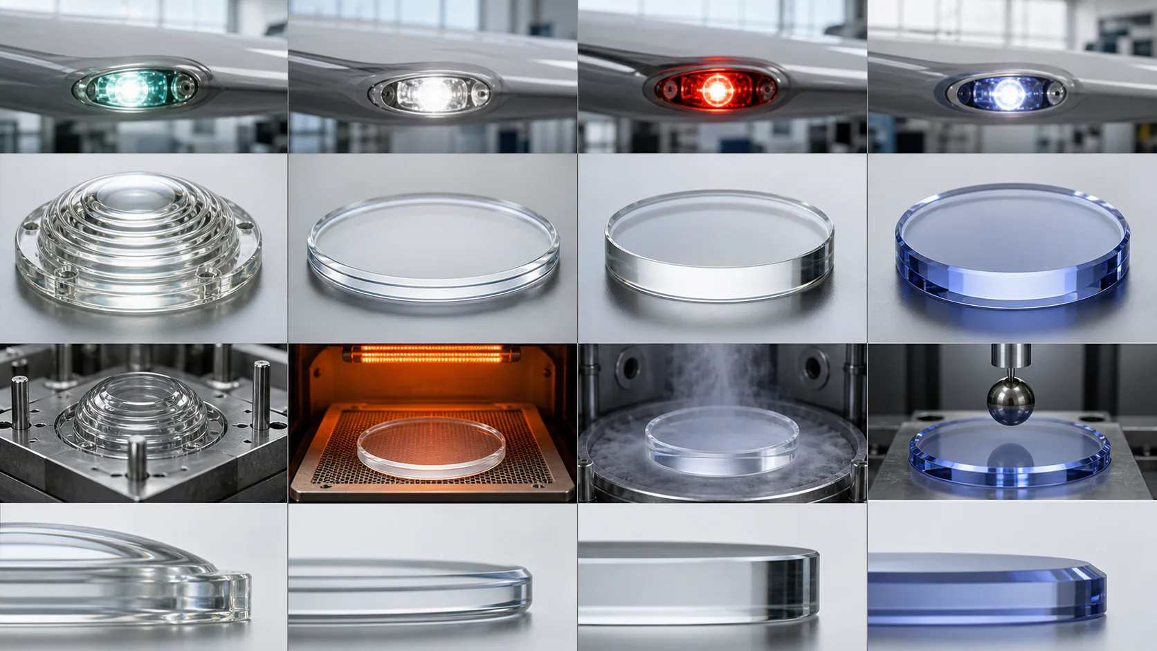
| Aviation signal color | Colored optical glass | Stable spectral-filtering function | Thickness, melt and source dependence | LED matching, chromaticity and intensity |
| Severe erosion or high temperature | Sapphire, a non-glass alternative | Hardness, erosion and high-temperature performance | Cost, birefringence, crystal orientation and machining | Complete optical path and installed system |
Glass Material Selection for Aerospace and Airfield Lighting
There is no single “best aerospace glass.” Borosilicate, aluminosilicate, fused silica, colored optical glass, and sapphire solve different combinations of thermal, mechanical, spectral, manufacturing, weight, and cost problems. Material selection becomes clearer when the application is treated as a set of trade-offs and when catalogue properties are separated from the behavior of the finished, edged, coated, and mounted part.
How should an OEM select a glass material?
Material selection should begin with mandatory system limits rather than a preferred glass name. Screen candidates through five gates: wavelength and color; temperature, fluids and weather; load path and fracture risk; geometry and production route; and program controls such as approved sources, traceability, obsolescence and lifecycle cost.
Separate catalogue properties from characteristics created by the finished part. Thickness, curvature, edges, forming, annealing, strengthening, printing, coating, sealing and mounting can all change optical or mechanical behavior. A weighted comparison is useful only after non-negotiable limits are identified. Material data create a shortlist; production-representative parts and the configured assembly establish suitability.
For every proposed grade, record the manufacturer and exact designation, product form, available thickness or blank size, controlled property range, typical-only values, manufacturing route, source status and change-notification expectation. Compare alternatives under equivalent wavelengths, temperatures, specimen conditions and units. The design authority should approve any equivalence claim because a material substitution can change optics, forming yield, heat treatment, coating adhesion and mounted stress simultaneously.
Borosilicate and aluminosilicate glass
Borosilicate is a common starting point when moderate-to-low thermal expansion, chemical durability and clear visible transmission are important. It can suit heat-exposed covers, illumination optics and components whose mounting must limit differential movement. The exact grade, product form and forming route still control refractive index, thickness range, strengthening options, defects and cost.
As one manufacturer example, the SCHOTT BOROFLOAT 33 data report properties for that named sheet-glass grade and stated test conditions. Those figures are not a universal borosilicate specification and do not automatically describe a pressed optic. An OEM callout should identify the controlled grade or agreed equivalent, product form, lot evidence and required finished-part results.
Aluminosilicate can be attractive for thin components that need an ion-exchange strengthening route. Its value depends on compatible chemistry, obtainable surface compression and depth, edge preparation, flatness and acceptable optical effects. Higher forming and processing costs may be justified where installed mass and handling margin matter.
For either family, verify the actual edges, coating, seals, frame and temperature cycle. “Low expansion” or “chemically strengthened” is not an assembly acceptance criterion; the mounted component must preserve fit, alignment, optical performance and required durability.
Fused silica, soda-lime, colored glass and sapphire
Fused silica is considered where exceptionally low thermal expansion, ultraviolet transmission in a suitable grade, wavefront stability or specified homogeneity justifies the material and finishing cost. A Corning HPFS product sheet illustrates grade-specific data, not a generic guarantee for every fused-silica product. Define grade, product form, wavelength band, OH content where relevant, inclusion or homogeneity requirements and the installed thermal mismatch.
Soda-lime glass may be appropriate for cost-sensitive parts in moderate thermal and chemical environments. Availability and formability are advantages; higher expansion, thick-section tint and thermal-shock margin require explicit review. It should neither be substituted for a controlled borosilicate part merely because dimensions match nor rejected when finished-part evidence shows that it meets the actual requirement.
Colored optical glass is a functional spectral material. Control the composition or approved grade, material melt, full spectral transmission curve, minimum and maximum thickness, orientation and the effective path length through curved regions. Record the permitted LED manufacturer, type and bin, operating point and temperature range. Annealing, heat treatment, polishing and coating can change thickness, stress or spectral behavior and therefore require correlated checks.
Component evidence for colored glass can include melt identity, spectral data, thickness map, visual zones and process records. Final aviation color and intensity belong to the complete source-filter-optic assembly; use the Optical Design, Color & LED Matching guide for colorimetric conditions and system acceptance.
Sapphire is a single-crystal ceramic, not glass. Its hardness, erosion resistance and high-temperature performance can justify its cost in severe applications, but crystal orientation, birefringence, machining, coating, joining and availability need evaluation. Specify it as a non-glass alternative and approve it only through the relevant complete optical and mounted-system tests.
Thermal-expansion and mounting inputs
Glass and housing materials move by different amounts as temperature changes. A low-CTE glass can reduce its own dimensional change yet create greater relative movement against an aluminum frame. The seal, adhesive and contact geometry determine whether that movement is absorbed or converted into edge and surface stress.
| Input | Define for the assembly analysis |
|---|---|
| Glass | CTE curve, dimensions, thickness, elastic properties and allowable stress basis |
| Housing | Material, CTE, stiffness, tolerances and contact locations |
| Seal or adhesive | Thickness, compression, modulus, temperature behavior and aging |
| Temperature | Assembly condition, cold soak, source hot spots, gradients and transition rate |
| Geometry | Radial clearance, axial constraint, edge support and alignment datums |
| Verification | Stress, seal, alignment and optical performance in representative thermal states |
Compare expansion over the full operating range rather than one coefficient measured across a different interval. Calculate radial, axial and local movement from the assembly temperature through cold and hot conditions. Use controlled clearance, compliant gaskets, bond-line thickness or sliding features while preserving sealing and alignment. Reassess every material or frame substitution, then thermal-cycle the production-representative assembly and inspect its optics, leakage, retention and edge condition.
Include dimensional tolerance and assembly preload in the worst-case evaluation. Nominal clearance can disappear when the largest glass, smallest housing, seal swelling and cold contraction occur together. Likewise, excessive gasket compression can create permanent edge load even before the light is energized. Instrument development units where practical so calculated glass, frame and seal temperatures can be compared with the real transient thermal state.
Manufacturing and Surface Treatments
Manufacturing is not just the route used to obtain the drawing shape. Pressing, cutting, grinding, polishing, forming, strengthening, printing, frosting, and coating each leave characteristic effects on geometry, residual stress, surface quality, optical performance, and repeatability. Understanding those effects helps an OEM place tight tolerances where they improve function and avoid adding cost where the lighting or sealing system receives no benefit.
Selecting a forming and tooling route
The production route follows geometry, material compatibility, optical zones, tolerance, volume and acceptable tooling investment.
| Geometry and volume | Candidate route | Primary risks | Typical acceptance |
|---|---|---|---|
| Large prisms, thick covers or repeat volume | Conventional glass pressing | Fill, folds, cords, surface marks and mold wear | Profile, defects, annealing stress and complete-fixture beam |
| Small precision aspheres | Precision glass molding | Material compatibility, tool life and replication error | Surface form, centration and optical performance |
| Prototype, low quantity or simple window | CNC grinding and polishing | Material waste, subsurface damage and cycle time | Thickness, wedge, roughness and transmitted performance |
| Complex part with limited precision zones | Molded plus finished hybrid | Datum transfer, added cost and traceability | Formed geometry and locally finished optical surfaces |
| Shallow curve or large-area cover | Thermal forming or bending | Thickness change, distortion and tool marks | Profile, mounting datums and transmitted distortion |
Tooling must reproduce functional surfaces, datums, rims and orientation features while allowing realistic radii, glass flow, venting, release and thermal compensation. Control tool ownership, cavity identity, maintenance, repairs and revision. First pieces require dimensional and functional optical review; a part that fits can still shift a beam or change sealing.
Define cavity-specific identification and monitor features that can drift with wear, polishing or repair. A mold facet repair can alter prism angle; vent or parting-line work can move flash into a seal or optical zone. Record process recipe, charge or preform, mold temperature, cycle, annealing route and approved rework. Capability evidence should use the intended material, cavity and production rate rather than a specially selected demonstration piece.
A prototype route does not automatically represent production. A machined sample may prove fit and nominal angle but not molded surface texture, flow defects, residual stress or shrinkage. Qualification samples should therefore be made by the intended production route, or the differences and additional evidence should be explicitly approved.
Annealing, tempering and chemical strengthening
Annealing and strengthening have different purposes and must not be used as interchangeable terms.
| Process | Purpose | Key inputs | Primary risks | Acceptance evidence |
|---|---|---|---|---|
| Annealing | Reduce unintended residual stress | Material, thickness, loading pattern and cooling curve | Localized stress, distortion and delayed cracking | Polarized inspection or quantitative stress measurement |
| Thermal tempering | Create a controlled surface-compression profile | Thickness, geometry, heating and quench uniformity | Optical distortion, dimensional change and inability to machine later | Finished stress, shape and project-required fracture behavior |
| Chemical strengthening | Create compression through ion exchange | Compatible chemistry, time, temperature and surface condition | Warpage, stress non-uniformity and compression-layer damage | Surface compression, layer depth, flatness and optical inspection |
Annealing cycles depend on glass family, section thickness, thickness transitions, furnace uniformity and loading density. A visually acceptable formed part can still contain localized stress that later appears as birefringence, machining distortion or fracture. Record furnace, recipe, load pattern, time and cooling history.
Complete holes, cutting, grinding and major edge finishing before thermal or chemical strengthening unless a validated route explicitly permits otherwise. Post-strengthening machining can remove compression and introduce flaws. Final order must also respect printing, coatings, bath chemistry and layer-temperature limits. Inspect the finished geometry after every process capable of changing stress, form or optical behavior.
Define strengthening evidence on the actual finished thickness and geometry. A process certificate without the part number, batch, method, sample plan and acceptance limits cannot demonstrate that the approved compression profile was achieved. Where optical distortion or polarization matters, correlate stress measurements with flatness, transmitted behavior or the complete viewing and lighting system. Rework and thermal exposure after strengthening require explicit disposition because they may alter the controlled stress state.
Precision finishing and functional optical zones
Use lapping or polishing only where molded, drawn, cut or formed surfaces cannot meet the required thickness, wedge, surface form, roughness, scatter, sealing or optical performance. Local finishing of entrance, exit or datum surfaces can be more economical than polishing an entire illumination optic. Non-optical mounting areas can remain molded or finely ground when they still meet contact, sealing, cleanliness and strength requirements.
Edges deserve their own functional zones because glass failures frequently start at perimeter flaws or point contact. Define seaming, chamfer or radius from the actual thickness, seal, clearance and load path rather than applying one generic aerospace dimension. Specify allowable chips, transition into the faces, holes or slots, no-contact areas and inspection lighting. A polished clear aperture cannot compensate for an uncontrolled loaded edge.
Define clear aperture, optical and cosmetic zones, support condition, material-removal allowance and measurable acceptance method. Thin or curved parts require stable blocking to avoid induced bow; colored glass requires thickness control because finishing changes spectral path length. Inspect wedge, profile, roughness or scatter, edges and possible subsurface damage after finishing and again after coating or strengthening if those operations can change the result.
For curved covers, complete DFM before freezing CAD. Identify installed orientation, trim allowance, parting-line or tooling zones, realistic corner radii, wall-thickness strategy and coating-fixture access. Measure the profile relative to functional mounting datums and correlate free-state geometry with the installed optical result.
Detailed transmitted-wavefront and imaging-window controls belong in the Cockpit Display Glass & Aerospace Optical Windows guide. This page uses precision finishing as a manufacturing decision, not a reason to impose imaging-grade polish on every lighting component.
Process compatibility: texture, printing, strengthening and coating
Release one controlled route showing how irreversible operations and layer-temperature limits interact.
| Operation | Sequence requirement | What it can damage or change | Key record |
|---|---|---|---|
| Cutting and grinding | Normally before strengthening | Edges, dimensions and subsurface condition | Drawing revision, tool or method and edge inspection |
| Annealing | After forming and before stress-sensitive finishing decisions | Dimensions, residual stress and colored-glass behavior | Furnace, load and temperature cycle |
| Strengthening | After major shape and edge processing | Flatness, dimensions and later high-temperature options | Batch, surface stress and layer depth where applicable |
| Frosting or etching | Located according to optical, strength and cleaning needs | Strength, contamination, seal lands and scatter | Area, process parameters and approved boundary sample |
| Printing | Coordinated with bending, strengthening and coating | Sealing, bonding, light leakage and non-glass material compliance | Ink batch, cure, artwork revision and registration |
| Coating | Applied to a clean and dimensionally stable surface | Later heat, ion exchange, cleaning and adhesion | Coating batch, side, spectral result and durability |
| Final inspection | After all irreversible operations and approved rework | — | Material, furnace, strengthening, coating, ink and rework traceability |
Texture should be specified by haze, total and diffuse transmission, angular spread, uniformity, surface side and masked zones rather than words such as “light frost.” Protect loaded edges and seal lands from unnecessary roughening and verify cleaning where the texture is exposed.
Printing requires controlled artwork, opacity, color, pinholes, registration, cure and compatibility with seals, adhesives, fluids and environmental requirements. Coatings require stated side, optical band, angle range, adhesion and cleaning durability. Final acceptance applies to the finished part—not an intermediate coupon—and unapproved polishing, touch-up or layer substitution should be prohibited.
Production evidence: forming, finishing and heat treatment
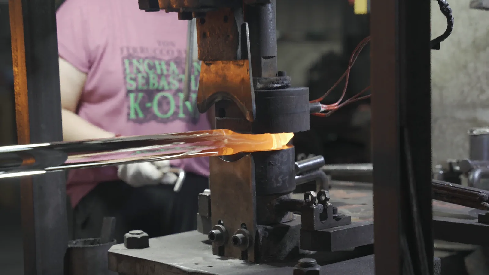
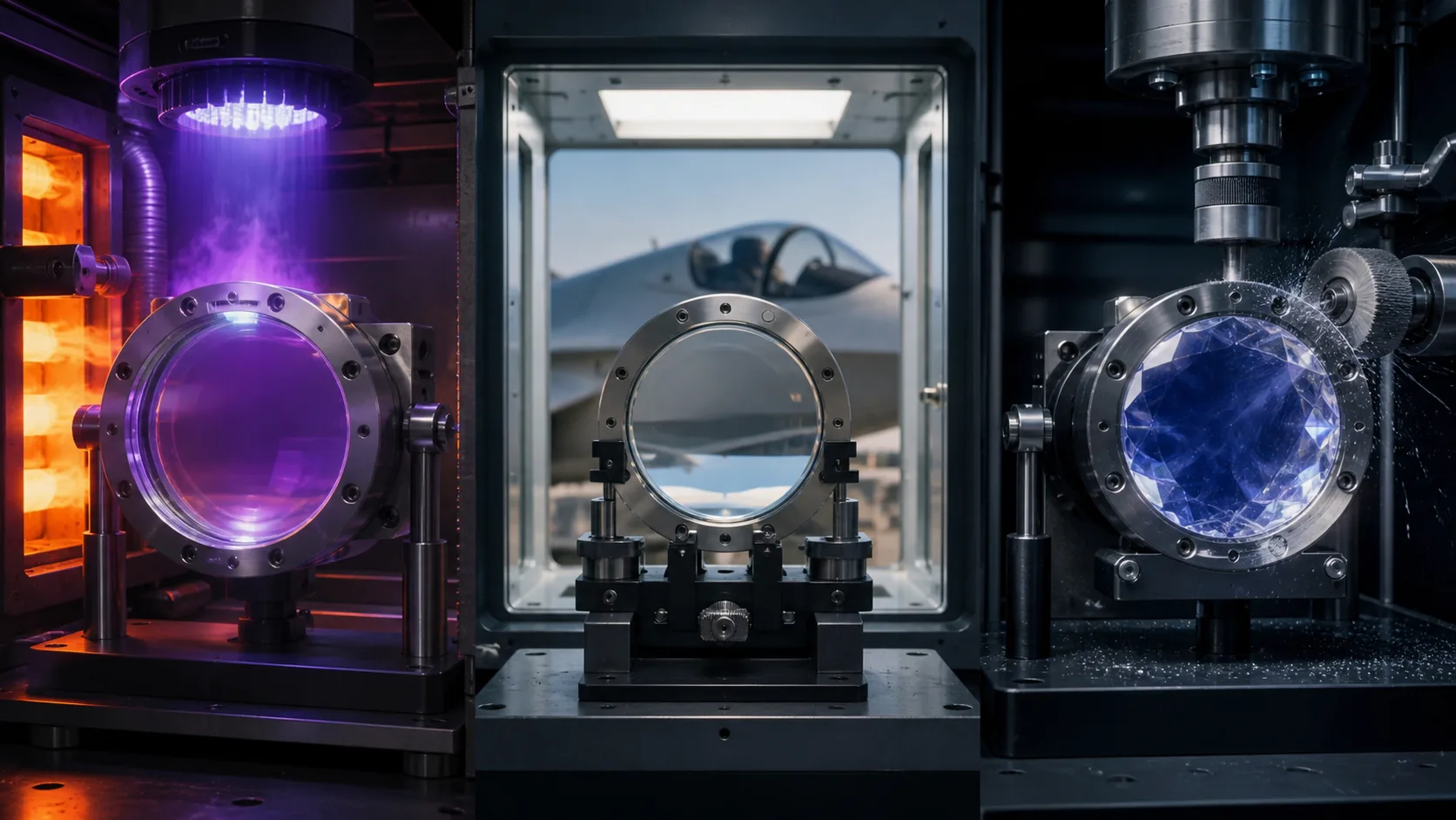
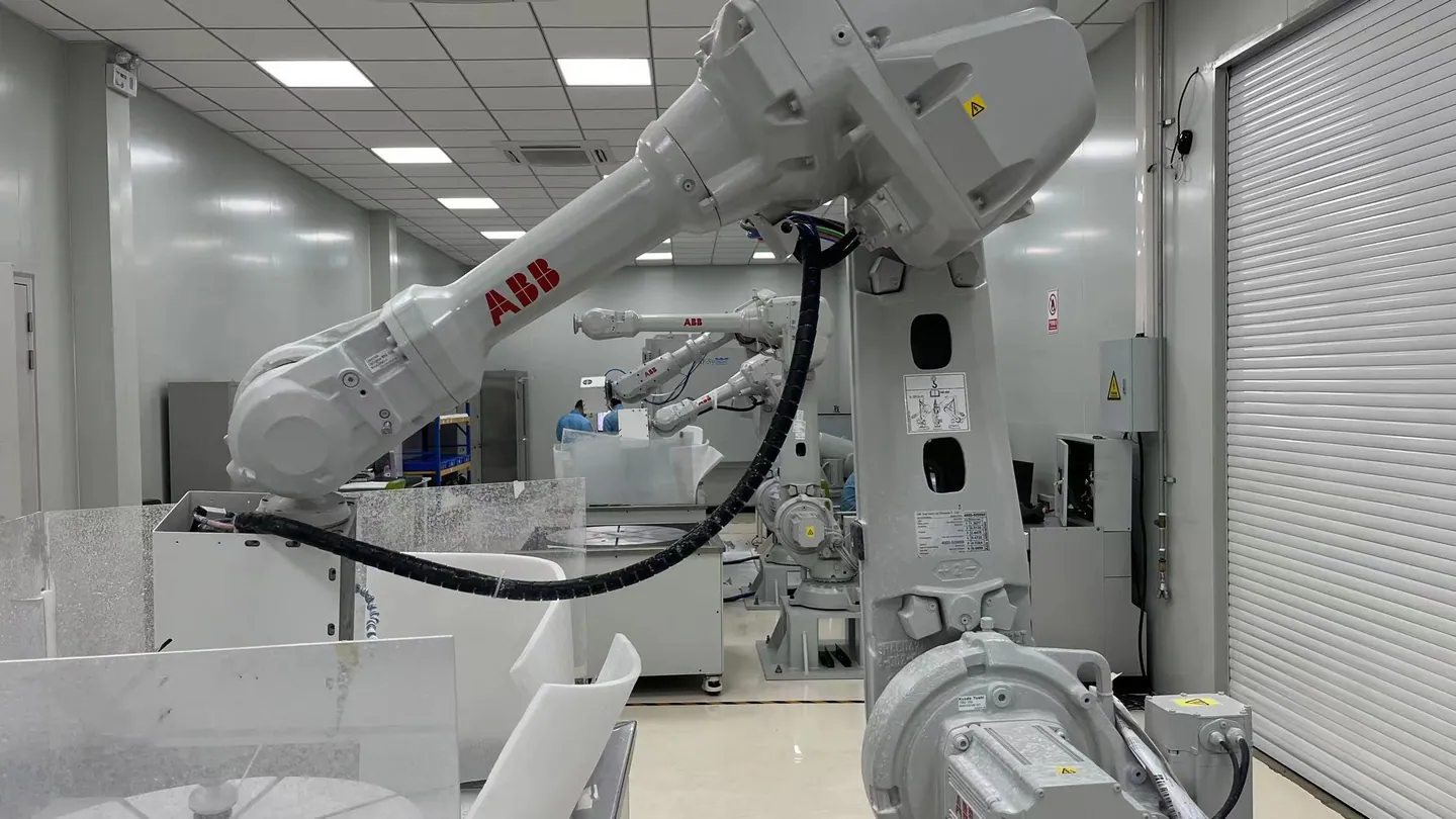
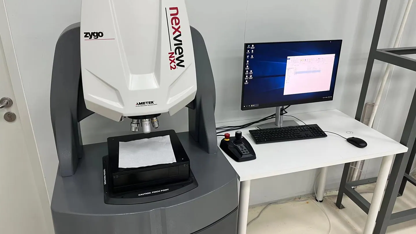
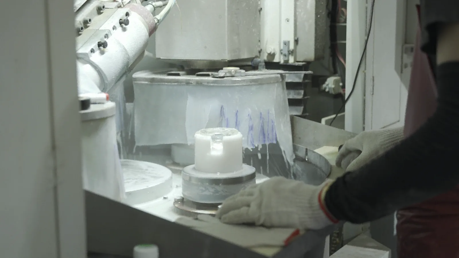
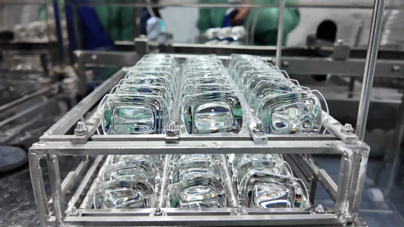
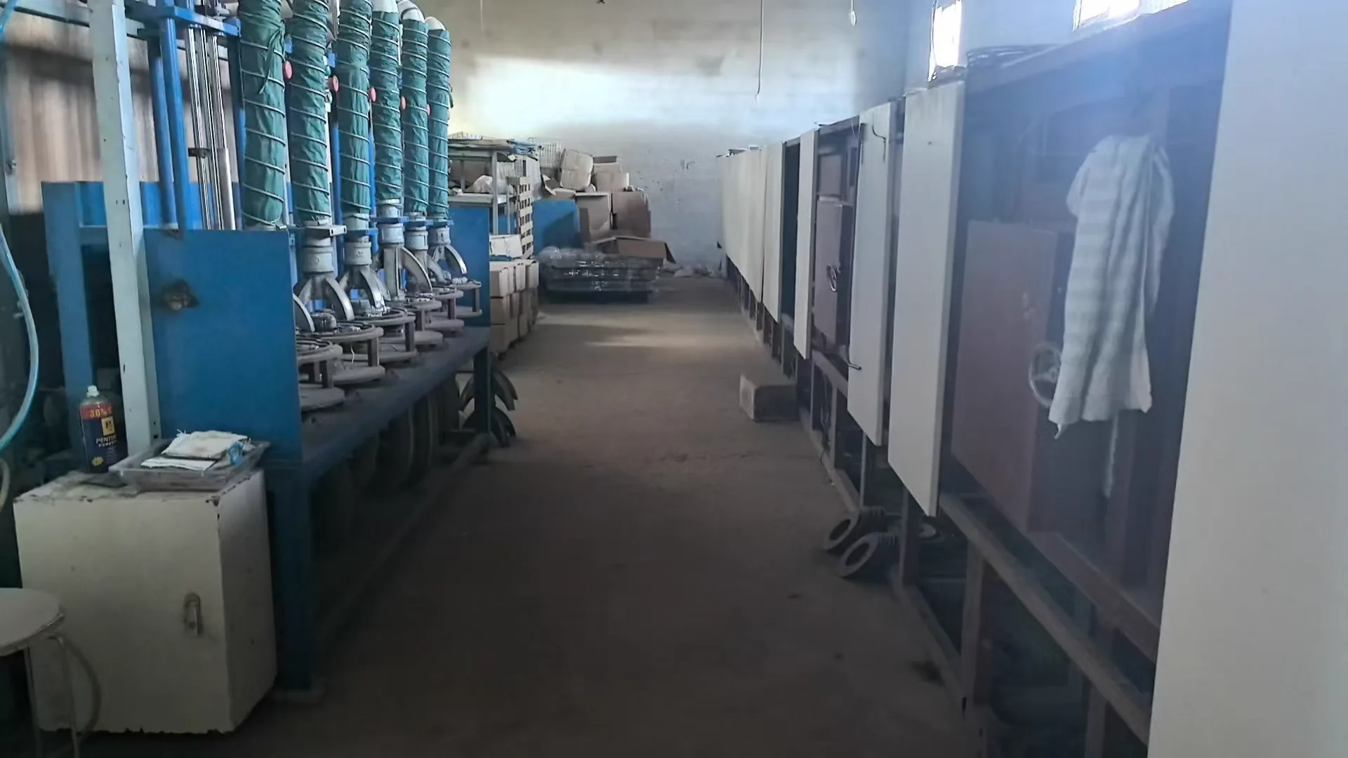
These photographs document representative production operations. They support a supplier-capability review, but they do not show that every aviation component follows the same route or that a photographed part is qualified for an aircraft or airfield application.
| Process stage | Control that matters | Evidence retained for an approved part |
|---|---|---|
| Forming | Material lot, charge, tool revision, temperature-time cycle and cooling | Traveler, lot link, process revision, first-piece dimensions and approved sample comparison |
| Grinding or polishing | Datum, removal, profile, edge condition, cleaning and handling | In-process measurements, final dimensional or optical report and nonconformance disposition |
| Annealing or strengthening | Validated cycle, loading pattern and material compatibility | Furnace or process record plus the required stress, strength, fragmentation or optical verification |
| Final release | Drawing revision, sampling plan, appearance zones and packaging | Lot inspection, material and process records, traceability, approval status and change history |
Official and standards references for this guide
Source status was reviewed on August 12, 2026. The contract, certification basis, approved equipment configuration and controlled document revision determine actual applicability. Obtain authorized copies of paid standards.
- ISO, ISO 10110-1:2019 - Preparation of drawings for optical elements and systems; it provides drawing notation rather than an “aerospace-grade” material designation or product qualification.
- ISO, ISO 10110-5:2026 - Surface form tolerances, published in May 2026, for applicable drawing controls rather than complete-equipment qualification.
- ISO, ISO 10110-7:2017 - Surface imperfections, confirmed and published on the review date, for finished optical surfaces and assemblies when adopted by the project.
- FAA, AC 150/5345-46F only for covered airport-light fixture applications. It is not a universal specification for aerospace glass materials or manufacturing routes.
Contact Us
Your feedback fuels our growth, and your questions drive our solutions.
We value your feedback, inquiries, and suggestions. Please feel free to get in touch with us
General inquiries
Please contact us via sales@bo-glass.com, and we will reply to you as soon as possible.
Interested to work with us
Drop your resume at info@bo-glass.com
and we will get back to you shortly.
We uses the contact information you provide to us to contact you about our relevent content, products, and services.