
Manufacturing and Design Guidelines
Molten Glass Blowing

Custom furnace-blown glass for lighting, decorative products and hollow components. Development brings shape, appearance and assembly requirements together, with the forming route, finishing and inspection defined around the component's intended use.
Overview and Applications
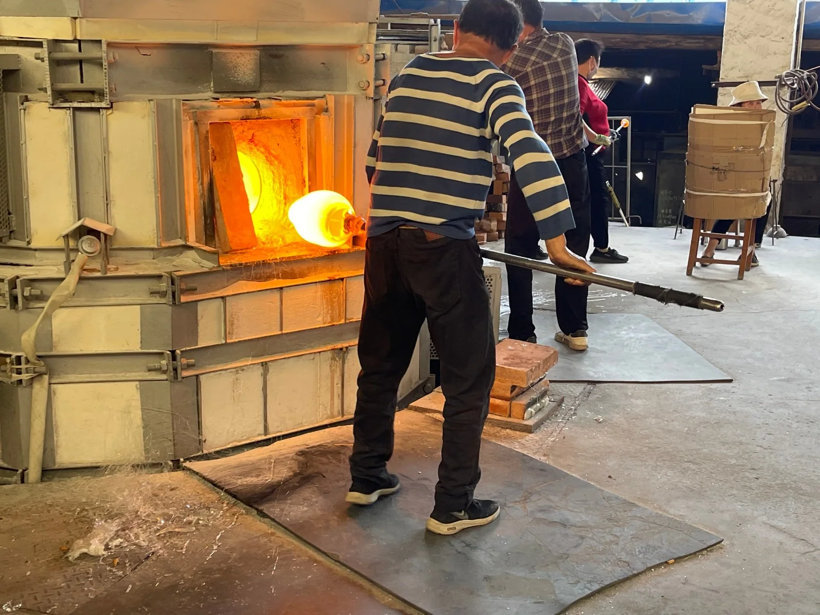
Molten glass blowing shapes hot glass through inflation, movement and tools. Free blowing develops the form without a mould defining the complete body; mould blowing uses a cavity to establish the contacted exterior. A product can combine mould forming with later hand shaping and finishing.
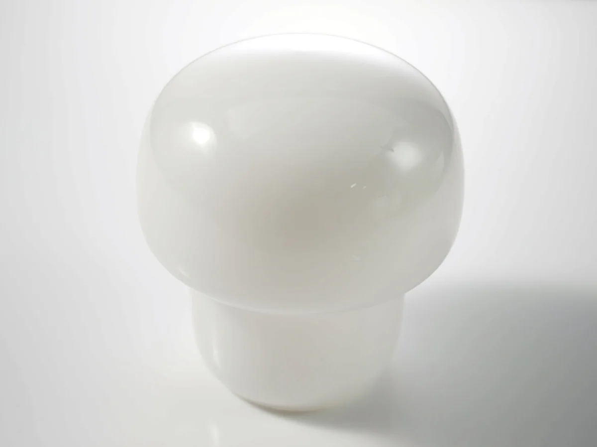
BO-Glass's furnace-blowing service covers custom lighting glass and decorative hollow products. The route is assessed against the design, material, appearance and planned quantities.
This route is useful when a hollow form, expressive surface or distinctive silhouette is central to the product, while its opening, support and mating features still need a clear specification.
Swipe horizontally to view all columns.
| Product direction | Main design priorities |
|---|---|
| Lampshades, globes and pendant glass | Holder fit, openings, light distribution and visible appearance |
| Vessels and decorative forms | Silhouette, rim condition, capacity and standing support |
| Custom hollow components | Internal clearance, mounting features and integration with mating parts |
This service concerns glass supplied molten from a furnace. Tube-and-rod lampworking and glass pressing involve different forming methods and need their own manufacturing review.
Glass Materials and Appearance
Material selection starts with the application: temperature exposure, contents, cleaning, optical requirements and contact with other components. The glass grade and production route need to suit those conditions together.
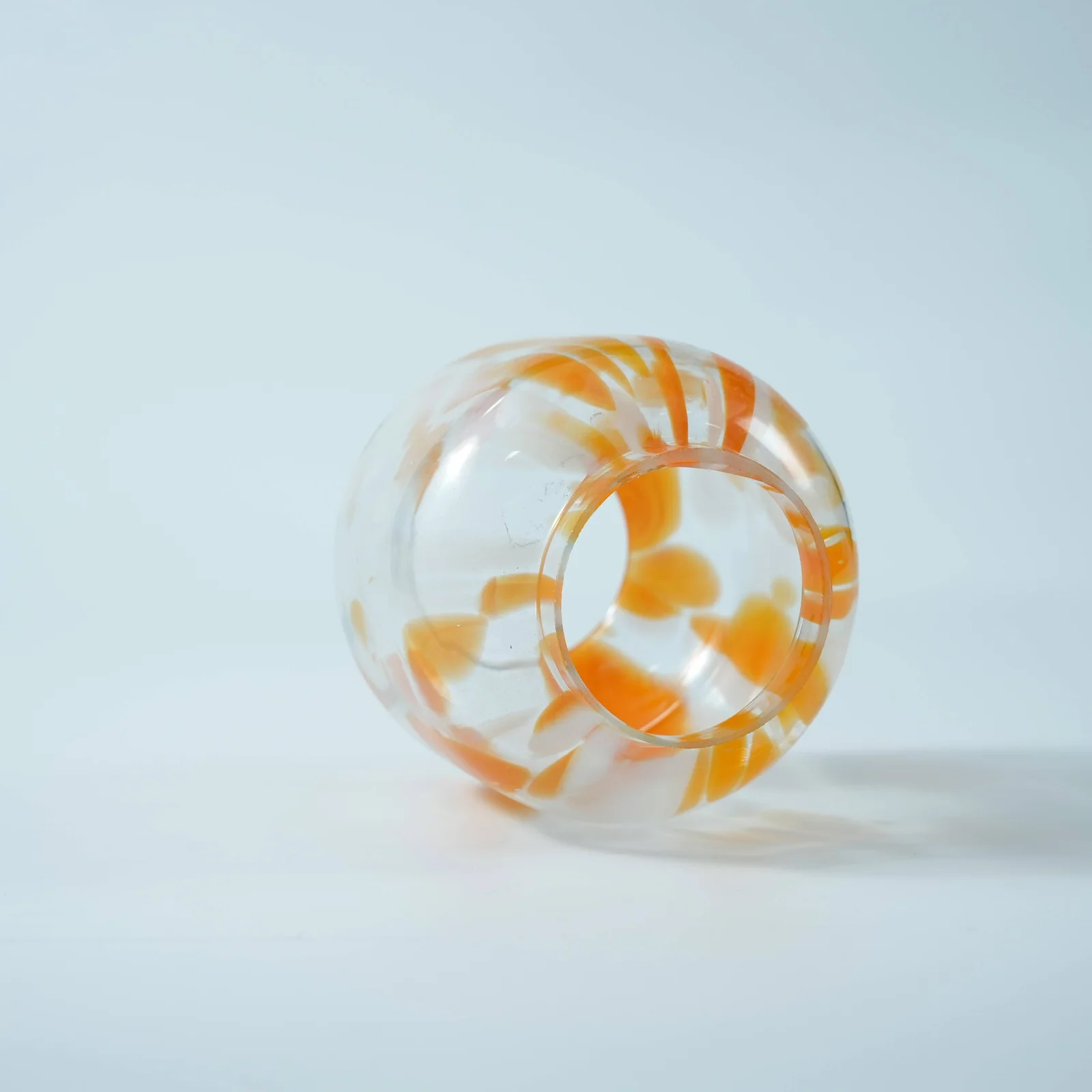
Clear, coloured and opal appearances create different visual results. Colour can be within the glass, combined in layers or applied as a surface treatment. Frosting, printing, paint and other decoration should be specified separately from the body material.
Physical references help establish colour, texture and permitted variation. For lighting products, the appearance under the intended light source can be as important as the unlit sample.
Glass-family names alone do not establish a finished-product rating. Where materials are joined, compatibility also needs review. The selected construction and finish become part of the sample approval, alongside the relevant application checks.
Product Design and Tooling
A workable design defines the surfaces that matter in use. For a shade, these may be its opening, seating face and clearance for a holder. For a vessel, the rim, internal access and standing area may determine acceptance.
Design review considers:
- Overall shape, sections and the relationship between openings and body.
- Local wall requirements, heavy bases and changes in section.
- Mould release, visible seams, texture and tool-contact areas.
- Mating components, finished edges and material needed for later operations.
Drawings, models and reference samples communicate different information. A photograph can show the intended effect, while a dimensioned section explains a concealed interface.
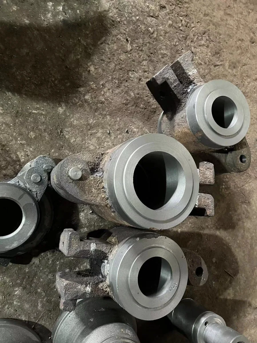
Tooling may include moulds, inserts, forming tools, supports and inspection gauges. The scope follows the complete component, including features established after blowing. Critical dimensions and permissible handmade variation are agreed through design review and representative samples.
Some areas can allow visual variation while others locate against fixed hardware. Distinguishing those priorities keeps development focused: the body may have a handmade character, while a finished opening is assessed against its agreed interface.
From Gathering to the Finished Component
The forming sequence begins with an identified glass and a suitable melt condition. Glass is gathered onto a blowpipe, prepared into an initial hollow form and developed through inflation, rotation, tools and reheating. A mould is introduced where the selected route calls for one.
Openings, rims or additions may require further hot working or transfer to another support. Annealing and the specified finishing operations then bring the component towards its supplied condition.
Consistency depends on the sequence as a whole. The starting glass, local heat, movement, inflation and tooling interact; one setting does not independently establish the result. Development connects those conditions with finished samples and the features the customer needs to approve.
Annealing, Finishing and Quality Control
Annealing uses a controlled thermal cycle to reduce residual stress. The cycle depends on the glass and geometry, including thick sections and applied features. Its completion is supported by the appropriate product assessment rather than treated as proof of every quality requirement.
Finishing can establish openings, rims, bases, edges or surface treatments. The selected operations and their availability are confirmed for the project. Dimensions and appearance are assessed after the operations capable of changing them.
Acceptance may cover local thickness, finished dimensions, assembly fit, appearance, residual stress and application tests. These characteristics provide separate evidence: equal weight does not establish equal wall distribution, and a good-looking surface does not prove performance.
Inspection methods, viewing conditions and acceptance limits form part of the product specification. Required reports and test evidence are identified during development.
Sampling, Repeat Production and Packaging
Samples have different purposes. An early form can establish silhouette; a completed sample can demonstrate finished interfaces and appearance. Approval records should state the condition represented and any accepted limitations.
Swipe horizontally to view all columns.
| Approval stage | What it establishes |
|---|---|
| Initial development | Proposed shape, construction and forming approach |
| Finished sample | Dimensions, interfaces, appearance and specified checks |
| Production release | Batch inspection, identification and agreed supply requirements |
Repeat production uses the approved drawing, material description, tooling references and acceptance plan. Changes to material, tooling or treatment are reviewed against the characteristics they can affect.
Packaging is part of the supplied product. Protection considers exposed rims, projections, decorated surfaces, movement and contact between pieces. Batch identification and agreed inspection records support traceability. Quantities, packaging format and the evidence needed for release are established for the individual project.
Technical Guides for Your Project
The guides below explain the decisions behind a custom blown glass project. Use the topic closest to the current question, from early design through production troubleshooting.
Product Design Guidelines
Define geometry, openings, wall distribution and assembly requirements before tooling. The product design guide connects the drawing with forming, finishing and sample approval.
Glass Selection and Melt Preparation
Understand glass identification, appearance, input routes and melt-quality evidence. The materials guide distinguishes customer requirements from the controls managed by the melting organisation.
Blowpipes, Moulds and Tooling
Review the tooling system beyond the cavity. The tooling guide covers pipes, supports, mould construction, surface preparation, gauges and representative trials.
Process Control
See how gathering, heat, movement, inflation and transfer influence the result. The process-control guide explains operating checkpoints and their connection to finished-product evidence.
Annealing, Finishing and Quality Inspection
Plan the supplied condition, edges, surfaces and inspection methods. The quality guide separates thermal treatment, dimensional checks, appearance assessment and application testing.
Defects and Troubleshooting
Describe a problem, preserve evidence and evaluate corrective changes. The troubleshooting guide distinguishes observations and hypotheses from a verified cause and correction.
Frequently Asked Questions
Can a project start from a concept or reference sample?
Concept images and samples can support an initial review. The design then needs defined dimensions, application conditions and critical interfaces. Features still open for discussion should be distinguished from requirements already fixed.
Does every blown glass component need a mould?
No. Free blowing and mould blowing suit different designs and appearance requirements, and a project may combine them. The route depends on shape, details, functional features and the repeatability required.
How are tolerances and acceptance limits established?
They follow the feature's function, glass, geometry and finishing route. Critical interfaces need defined measurement methods and sample evidence. A tolerance demonstrated for one feature should not be assumed across every surface or product.
What determines quantities and the production schedule?
Tooling, material selection, finishing, inspection and sample approval affect planning. Development samples, order quantities and delivery requirements are reviewed for the specific project; the confirmed supply terms should reflect its approved scope.
Contact Us
Discuss Your Custom Glass Project
Share your drawing, photos or dimensions, together with the intended use and target quantity. We will review your requirements and discuss the next steps.
Sales Enquiries
Email sales@bo-glass.com with your part description, intended use and target quantity.
Send Your Design
Use the form to upload a drawing or describe an existing part. Mark critical dimensions and tell us which surfaces or features matter most.
Request a Custom Glass Quote
Upload a drawing or share dimensions, quantity, intended use and finish. Include any heat, pressure or chemical exposure.
Your drawings remain confidential.
We use the contact details you provide to respond to your enquiry. See our Privacy Policy for more information.