
Molten Glass Blowing Process Control
Consistent blown glass depends on coordinating the starting glass, heat, movement, air and tooling throughout the forming sequence. This guide helps designers, engineers and purchasing teams understand the controls and production evidence needed to connect a repeatable process with an acceptable finished component.
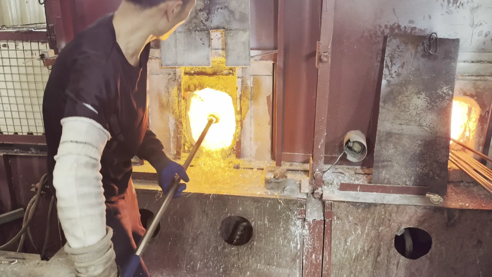
Quick-start: identify these five items
- Product requirements, critical features and the condition in which they are inspected.
- Glass identity, melt readiness and any combined-glass construction.
- Tooling references, forming sequence and intermediate checkpoints.
- Measured conditions, observable responses and demonstrated process combinations.
- Sample records, finished-product checks and actions for deviations or restarts.
1. Define the Process Window from Product Requirements
Begin with the drawing, intended application and acceptance criteria. Identify the features controlling fit, appearance and performance, then connect them to the stages that influence them. A shade may need particular control of opening alignment and illuminated appearance; a vessel may prioritise capacity, standing stability and closure fit.

The customer defines the required result. The manufacturer establishes and validates the forming sequence, operating conditions, inspection methods and response to deviations for its material and equipment.
Swipe horizontally to view all columns.
| Control requirement | What it establishes |
|---|---|
| Target condition | The normal setting or working condition used in production |
| Validated process range | Combinations demonstrated to produce acceptable components |
| Action or stop condition | A deviation requiring adjustment, investigation or interruption |
| Product acceptance limit | What the finished component must satisfy |
Keep these requirements distinct. A setting within its permitted range does not prove product conformity. Several parameters can each lie within their individual limits while forming a combination never evaluated together.
During development, connect process observations with representative finished samples. Record the resulting operating window, its limitations and the checks supporting release. The control plan should explain both what is normally done and what happens when the expected response is absent.
For each checkpoint, identify the observation or measurement, the responsible role and the decision it supports. Where judgement is visual, use a defined stage and reference condition so operators are comparing the same feature rather than relying on an unexplained instruction such as “ready to blow”.
2. Check Material, Melt and Tooling Readiness
Start from an identifiable production condition. Confirm glass grade, colour and melt reference, including additional glass intended for layers, handles or other applied features. Compatibility of joined glasses should already have been established during material selection.
The melt needs to meet its defined gathering-readiness criteria. Recent charging, furnace changes or interruptions may require new checks before forming resumes. A previous acceptable batch does not establish readiness after a change.
Confirm pipe and support condition, available tools and gauges, and the current drawing and process instructions. For mould blowing, check mould identity, revision, assembly, closure, venting and preparation. Establish readiness of reheating and annealing equipment before beginning a sequence that depends on them.
Match the setup review to the route. Free blowing and split-mould forming do not have identical requirements. Identify replacements, repairs and changed material inputs so any difference in results can be assessed against a known condition.
These checks establish the starting point; they do not replace the stage checks or finished-product inspection that follow.
3. Control the Gather, Initial Bubble and Preform
Gather quantity and distribution determine how much glass is available for the body, shoulder, neck and base. Define the manual practice demonstrated during development, including the number of gathers, preparation between gathers and shape before initial inflation.
With multiple gathers, review the condition of the existing glass and how additions build onto it. Uneven buildup or unintended trapped air can become more apparent as the form expands.
The initial bubble and surrounding glass establish the starting geometry for later work. Here, preform means the hot intermediate shape prepared before the next forming stage.
Swipe horizontally to view all columns.
| Checkpoint | What to observe | Why it matters |
|---|---|---|
| Gather | Shape, centring and distribution along the pipe | Establishes the initial allocation of glass |
| Surface and interior | Contamination or unintended bubbles | Identifies starting conditions needing assessment |
| Initial bubble | Position and surrounding glass distribution | Influences later expansion |
| Preform | Length, diameter, alignment and neck/base preparation | Establishes readiness for the next operation |
| Mould approach, where used | Shape, clearance and working response | Connects preparation with entry requirements |
Marvering and blocking are established preparation operations; their use affects both geometry and local heat loss. Treat their sequence and extent as part of the process. Reference profiles, photographs or sketches are useful when their viewing position and production stage are identified.
Define the response to an unsuitable starting form. More inflation may change its outline without correcting the original distribution.
Finished weight can support consistency checks when measured at the same defined stage. It is not a direct measurement of the original gather: separation, trimming and added features change the final mass. Record these distinctions when interpreting weight trends.
4. Coordinate Temperature, Rotation and Inflation
Temperature affects viscosity and therefore the glass response to gravity, inflation and tools. Different compositions have different viscosity–temperature relationships, illustrated in SCHOTT's technical discussion of glass viscosity. Material reference temperatures provide context, not a complete blowing recipe.
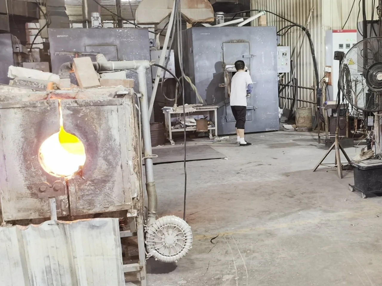
A furnace setpoint does not describe the changing temperature distribution of glass on the pipe. Exposure, contact and reheating affect regions differently; some may intentionally remain firmer while another is formed. Anchor timing to an identifiable event, such as leaving the reheating furnace or beginning mould entry. Equal total cycle times can conceal different time distributions between operations.
Define rotation and orientation stage by stage. Consider continuity, changes in direction, pipe angle, support position and any deliberate stretching or swinging. Symmetric and asymmetric products may require different movement. Rotating the glass inside a suitable mould and holding it stationary in a shaped cavity are distinct operations.
For manual work, describe the sequence and observable checkpoints. An estimated movement should not become a claimed measured speed. For assisted equipment, record the settings actually controlled by the system. Rotation can improve repeatability without independently proving uniform wall thickness.
Inflation also needs stage-specific control. Pressure, airflow and application time describe different aspects of delivery. In an assisted arrangement, identify measurement locations, operating pressure behaviour, valve timing and supply conditions where available. A static supply reading alone does not establish what happens during blowing.
For mouth blowing, document the intended glass response and sequence without inventing pressure measurements. If expansion is incomplete or uneven, assess starting form, temperature, elapsed time, orientation, air path and mould condition together. Increasing pressure alone may enlarge the piece while retaining an unsuitable distribution of glass.
5. Reheat for Local Wall Distribution
Give each reheat a defined purpose: further body expansion, opening preparation or attachment of a feature. Establish the region heated, position, movement and expected response, while protecting regions already at their intended shape.
Appearance, movement and timing can support trained observations of workability, as described in the Corning Museum of Glass hot-glass FAQ. Visible colour alone is not a universal temperature measurement. Record additional or unplanned reheats during development and investigation, especially when they alter the profile or later sequence.
Thermal distribution and glass distribution need to be assessed together. A warmer region may respond differently from a firmer neighbouring region during expansion. Relate these observations to completed samples rather than assuming an extra reheat restores the previous condition unchanged.
Define local thickness checks around the actual geometry: body sections at different heights, shoulders, corners, neck, heel, base and applied features where critical. Review the earlier gather, bubble position, heat history, orientation and timing when results show an unsuitable distribution.
Weight, wall thickness and geometry provide different evidence. Similar weights can conceal different distributions, and an acceptable external profile can conceal an unsuitable internal contour. Use weight alongside local measurements, dimensions and appearance. For lighting products, assess the completed component under the intended light source where wall variation affects the visual result.
6. Manage Mould Entry, Inflation and Release
Connect preform readiness with mould readiness. Before entry, confirm the required shape, working response, cavity condition and assembled tool. Review position, entry clearance, alignment, contact with the base and the relationship between closure and inflation.
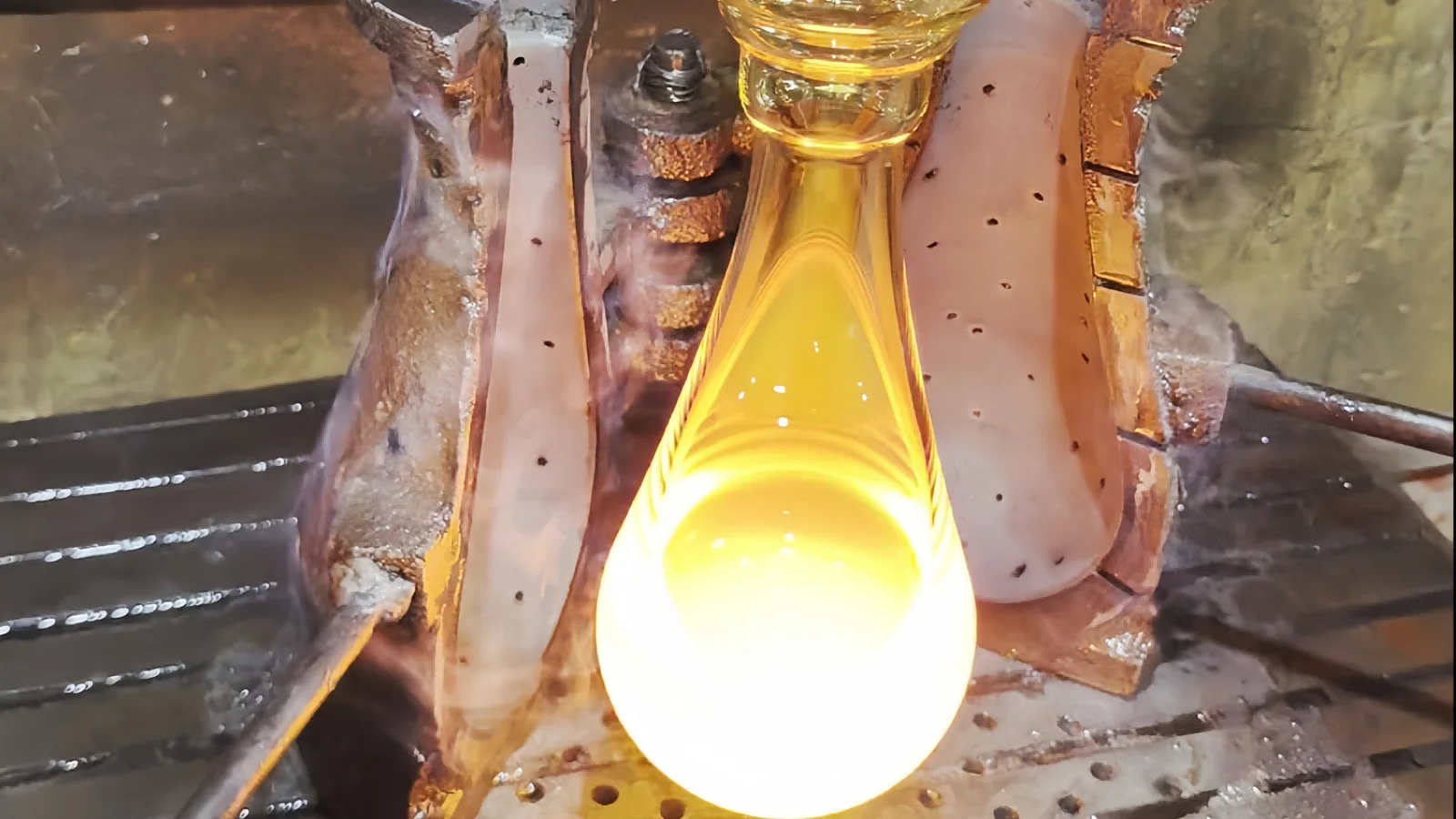
The sequence must provide a path for displaced air outside the expanding glass. Inflation air, cavity venting and mould cooling serve different functions; a change in one should not be interpreted as an equivalent change in another.
Mould thermal condition varies between start-up, repeated use and pauses. Record preparation and thermal observations at a defined point in the cycle. Surface preparation must match the selected system, including moisture or lining condition only where its established method requires it.
Establish inflation and release endpoints through trials. Reaching the cavity outline is one checkpoint; the glass must also tolerate opening, removal and handling without unacceptable deformation or surface damage.
Check the state after release as well as the appearance inside the mould. Support, contact and delays before the following operation can still alter the profile. Where rotation inside the mould is used, include it in the defined sequence rather than treating mould type alone as sufficient information.
7. Control Transfers, Openings and Annealing Handover
A transfer changes support, access and thermal conditions. Where a punty is used, define its attachment position, centring, support and separation sequence. Preserve the intended body profile and access for the next operation.
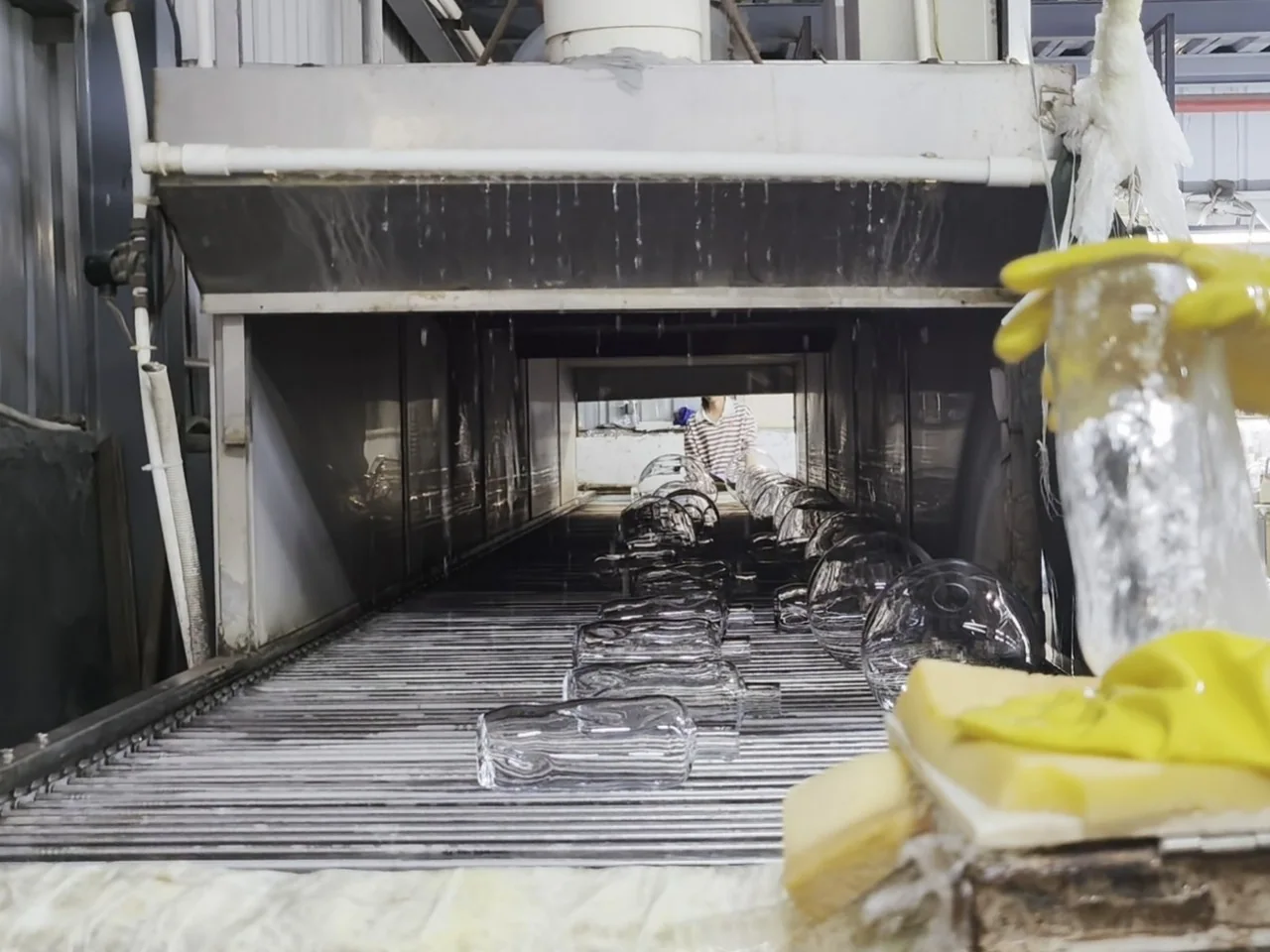
For openings and rims, identify the available material, reheating and shaping sequence, tool profiles, finishing allowance and inspection stage. A hot opening check is an intermediate reference unless it demonstrably represents the specified final condition.
For handles, feet, stems or other additions, control quantity, location and the thermal relationship between joined parts. Recheck alignment and local shape afterwards: later heating or contact can change a previously acceptable body.
Define the handover from final hot working to annealing. Control the interval, handling method, support, loading sequence and separation from adjacent pieces. Link the forming batch to the load and applicable annealing programme.
The manufacturer should establish and validate that programme for the selected glass and geometry, accounting for wall distribution and substantial additions. Reheating during forming does not demonstrate acceptable residual stress. Annealing also does not repair cracks, contamination or incorrect geometry.
Annealing uses controlled cooling to reduce residual stress; its outcome needs the appropriate finished-product assessment.
Connect forming, annealing and finishing records so final results can be traced to the complete route. Changes affecting the condition entering annealing belong in that review, even when the final annealing programme itself remains unchanged.
8. Record Conditions and Verify Product Results
Separate measurements, setpoints, estimates and trained observations. Each needs enough context to show what was established and how it relates to the product.
Swipe horizontally to view all columns.
| Record item | Context needed |
|---|---|
| Quantity or weight | Production stage, assessment method, additions and removed material |
| Temperature | Location, method, instrument settings and cycle stage |
| Inflation | Measurement point, pressure or flow where measured, and application timing |
| Movement | Controlled settings or the defined manual sequence and orientation |
| Reheating | Region, order, duration and additional reheats |
| Mould | Identity, preparation, thermal observations and cooling condition |
| Transfer and annealing | Support, timing, load identity and programme reference |
Select infrared measurement for the glass, temperature range and intended measurement depth. Wavelength, thickness, reflection and transmission affect the detected signal, as explained in Optris's glass-industry measurement guide. A general-purpose reading should not be treated as the target surface temperature without validation for the actual setup.
In-process checks provide early feedback on profile, alignment, opening preparation and visible deformation. Final inspection evaluates the specified condition after annealing and finishing. Select dimensions, local thickness, weight, residual stress, appearance and application checks according to product requirements; evidence for one characteristic does not establish another.
Use consistent references, support, lighting and measurement methods. Link rejected samples to their material, tool, team and production period where useful for investigation.
Statistical stability and conformity are separate questions. Stability concerns variation over time; conformity concerns the specified product limits. A stable process can still be off target or vary too widely. Conforming samples alone do not establish stability or capability. Capability assessment compares a stable process with specification limits, using suitable data and assumptions. It applies to the characteristic assessed rather than every requirement on the drawing.
9. Respond to Drift, Startup and Restart Conditions
When a deviation appears, identify potentially affected production and preserve samples, photographs, readings, timing and recent-change records. Investigate the full sequence before assigning a cause to one observation.
Define what permits the next stage to begin and what requires renewed checks.
Swipe horizontally to view all columns.
| Production event | Decision to establish |
|---|---|
| Initial start | Are melt, tools and the forming sequence ready? |
| Stage transition | Has the required shape, response or measured endpoint been reached? |
| Pause or restart | Which readiness and sample checks must be repeated? |
| Material or tool change | Which demonstrated conditions and product results need reassessment? |
| Corrective adjustment | What evidence supports returning to routine production? |
Start-up and restart can differ from sustained operation because tools and equipment have a different thermal history. Use a representative sample sequence; the first acceptable piece may not demonstrate continuing conformity.
Evaluate corrective changes through controlled trials, recording combinations where factors interact. Planned experiments may be useful when separate adjustments repeatedly obscure those interactions. Recheck the affected characteristic and other requirements the change could influence.
Keep the disposition of affected product separate from the decision to adjust the process. A successful trial shows what happened under its recorded conditions; it does not automatically release earlier production. Define the evidence required for each decision and preserve its connection to the relevant samples and lots.
Retain the operation sequence, demonstrated combinations, transition criteria, inspection methods and deviation actions in the current process revision. Changes to composition, size, wall distribution, tools, reheating or equipment may require partial or wider validation. Update the production window from supporting results rather than from a new setting alone.
References
- Corning Museum of Glass — Frequently Asked Questions: hot-glass workability and mould-blowing background.
- Corning Museum of Glass — Glassblowing Tools: preparation tools, blowpipes and punties.
- SCHOTT — TIE-31: Mechanical and Thermal Properties of Optical Glass: general viscosity–temperature relationships in Section 6.
- MO-SCI — Glass 101: Glass Annealing: controlled cooling and residual-stress reduction.
- Optris — Application Overview: Glass Industry: infrared measurement considerations.
- NIST/SEMATECH — What Is Process Capability?: stable processes and comparison with specification limits.
Contact Us
Discuss Your Custom Glass Project
Share your drawing, photos or dimensions, together with the intended use and target quantity. We will review your requirements and discuss the next steps.
Sales Enquiries
Email sales@bo-glass.com with your part description, intended use and target quantity.
Send Your Design
Use the form to upload a drawing or describe an existing part. Mark critical dimensions and tell us which surfaces or features matter most.
Request a Custom Glass Quote
Upload a drawing or share dimensions, quantity, intended use and finish. Include any heat, pressure or chemical exposure.
Your drawings remain confidential.
We use the contact details you provide to respond to your enquiry. See our Privacy Policy for more information.