
Molten Glass Blowing: Product Design Guidelines
A practical guide for designers, engineers and purchasing teams specifying custom glass lighting components, vessels and decorative products, covering shape, fit, function and appearance.
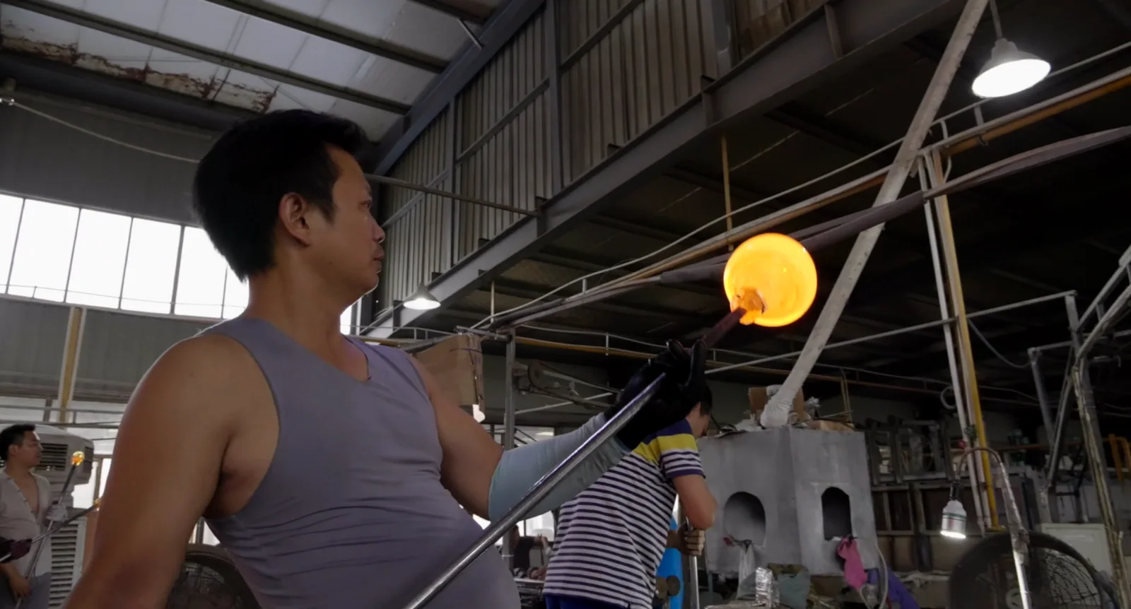
Before requesting a manufacturing review, prepare:
- Drawings or references: overall dimensions, sections, concept images and revision.
- Application: intended use, installation, service conditions and mating components.
- Material and finish: glass, colour, texture, edge treatment and decoration.
- Critical requirements: assembly fit, local thickness, appearance and acceptance criteria.
- Quantities: development samples, first order and expected repeat demand.
Starting with a concept? Mark unresolved choices as to be discussed and identify the requirements that are already fixed.
1. Define the Application and Forming Route
Start with the finished product's function. A shade must fit its holder and create the intended illuminated appearance; a vessel may need usable capacity, a comfortable rim and stable support. Separate essential requirements from aesthetic preferences.
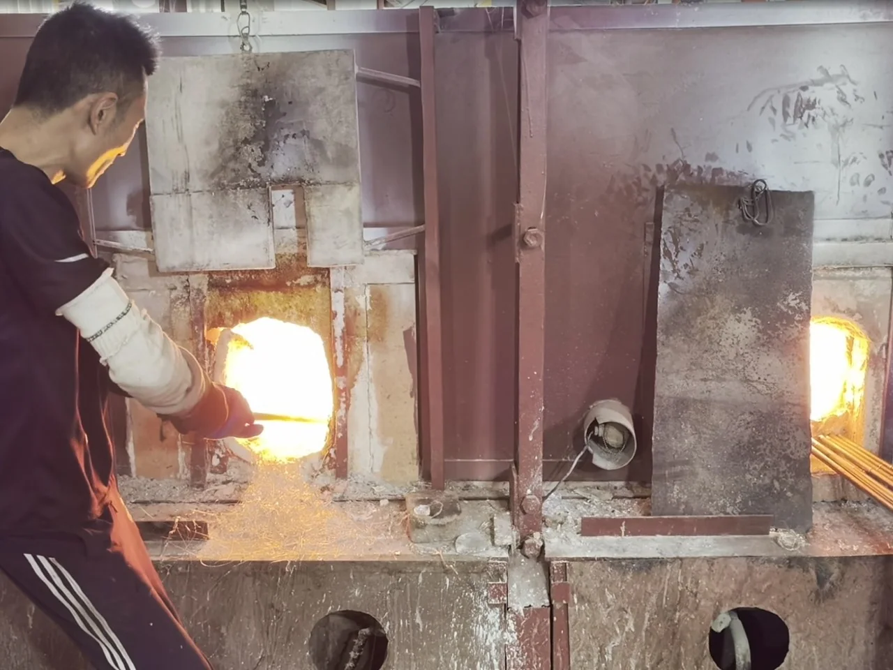
Describe installation orientation, contact with other components, contents, temperature exposure and changes, cleaning, handling and assembly loads. These conditions help identify the features that determine acceptance.
Free blowing shapes the body through inflation and manipulation without a mould defining the complete profile. Mould blowing expands a hollow glass blank against a cavity that controls the contacted exterior. Use the following comparison to guide discussion, rather than assuming a route from a photograph.
Swipe horizontally to view all columns.
| Review topic | Free blowing | Mould blowing |
|---|---|---|
| Body shape | Agree reference profiles and permitted silhouette variation. | Identify the exterior controlled by the cavity. |
| Repeatability | Review symmetry and glass distribution across samples. | Review repeatability of the moulded outline and separately finished features. |
| Surface details | Confirm how tools or later operations create the details. | Confirm cavity details, mould joints and any later expansion. |
| Functional interfaces | Identify openings or mounting surfaces needing further control. | Distinguish moulded features from interfaces completed afterwards. |
| Tooling and quantity | Discuss tools, forming sequence and planned quantities. | Discuss mould construction, release, development work and planned quantities. |
A mould can establish an intermediate form rather than the final profile. Confirm the complete sequence from forming through finished inspection.
Lampworking generally starts with tubes or rods softened locally in a flame. Pressing uses a plunger to displace glass. Automated container routes such as blow-and-blow and press-and-blow establish the initial blank differently and require a separate equipment and tooling assessment. Name the agreed route in the quotation and sample plan.
2. Specify Glass, Colour and Material Compatibility
“Clear glass”, “coloured glass” and “blown glass” are incomplete material descriptions. Identify the selected grade or agreed material description, or explain the thermal, chemical, optical and appearance properties needed if selection remains open.
Material properties and finished-product performance are separate considerations. Geometry, surface condition, thermal processing and application also affect suitability.
State whether the appearance comes from colour within the glass, combined clear and coloured glass, opal or other light-scattering glass, a coating, printing, decals or decoration. Specify coverage, treatment location and masking boundaries where relevant. For a lighting component, include its intended illuminated appearance.
When layers, handles, feet or decorative additions are fused together, identify the actual glasses being joined. Matching a nominal coefficient of thermal expansion alone does not establish compatibility: viscosity behaviour also matters. Bullseye's compatibility guidance explains this distinction.
Include the proposed material combination in sample development and thermal-process validation, supported by appropriate compatibility evidence.
3. Design the Geometry and Section Transitions
Show the complete three-dimensional form, including sections through shoulders, bases, openings and concealed areas. For asymmetric products, establish orientation and the relationship between features.
Review large diameters for glass distribution and support during forming; tall or slender bodies for straightness and shape retention; and broad shoulders with narrow necks for forming and opening access. Recesses, projections and multiple openings need a defined production sequence and access for finishing and inspection.
Pay particular attention to transitions: a narrow neck into a broad body, a thin wall into a heavy base, a flat panel into a corner, or an applied feature into the body. Where the design permits, consider smoother transitions and evaluate their effect on forming, thickness and service performance.
If a sharp external corner is essential, define the corresponding internal shape and local wall requirement. There is no universal corner radius for blown glass: establish it through the review of material, geometry, tooling, finishing and intended use.
Scaling an existing design requires reassessment of wall distribution, handling, tooling, thermal processing and finishing access. The drawing should describe the required result without assuming every feature is achievable in one operation.
4. Control Wall Distribution and Product Weight
A single wall-thickness value may not describe the rim, shoulder, body and base adequately. The quantity of glass, its thermal condition and the forming sequence influence distribution; glass viscosity changes strongly with temperature.
Specify measurable locations or inspection areas for the requirements that matter.
Swipe horizontally to view all columns.
| Area | Requirement to define |
|---|---|
| Rim or opening | Edge thickness, continuity and finishing requirements |
| Neck or mounting zone | Local thickness around attachment or sealing surfaces |
| Shoulder | Distribution through the body transition |
| Main body | Local minimum thickness and permitted variation |
| Lower transition | Thickness approaching the base |
| Base | Thickness profile, support geometry and finishing allowance |
Distinguish nominal, minimum and average thickness. Nominal thickness describes the intended design; a minimum establishes a lower acceptance limit at defined locations. An average can conceal a local thin area, so agree how such areas will be detected and evaluated.
Weight supports checks on total glass quantity but does not show where the glass is located. Agree weight limits separately from local thickness requirements.
External geometry, internal volume and wall distribution are related. Identify critical internal dimensions or usable capacity early; an external mould profile does not independently control every internal surface.
5. Specify Openings, Rims and Assembly Interfaces
Dimension openings in the condition supplied. If an opening is cut and ground, the drawing should specify its dimensions after those operations.
Openings, Necks and Rims
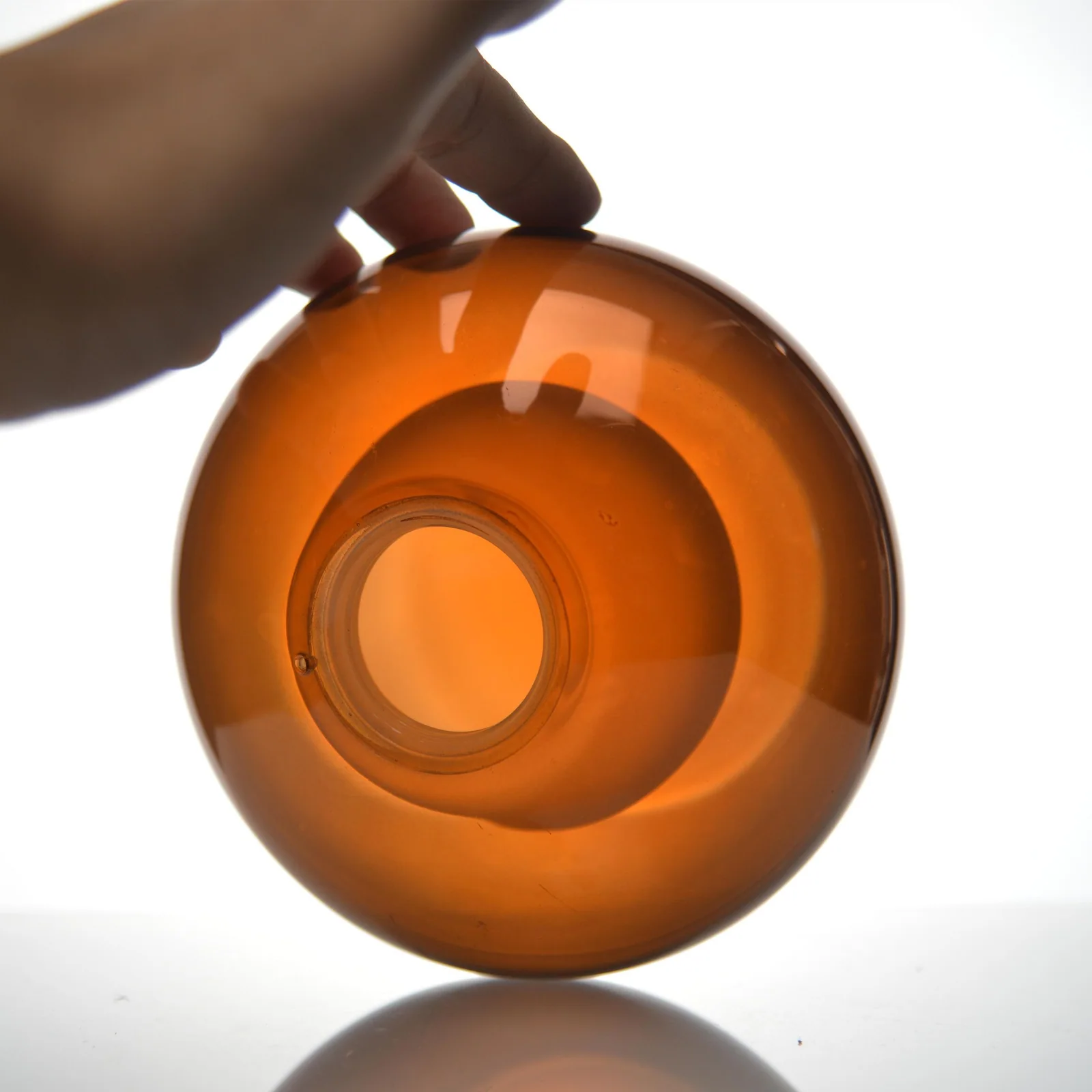
Define the opening diameter or profile, clearance over the required depth, neck length, relationship to the body axis, local wall thickness and edge radius or chamfer. Supply the mating holder or its drawing: one diameter alone may not establish whether it can enter, seat and locate correctly.
A rounded rim, cut-and-ground edge and flat sealing face perform different functions. Specify the edge profile, appearance and contact region, including any surface that seals against a gasket or closure.
Threads and Mechanical Assembly
Threads require geometry, engagement length, mating-component information and assembly requirements. Confirm how the selected process will produce and inspect them. Check both dimensional conformity and actual closure performance.
For metal, plastic or other mating parts, show supporting and locating surfaces, gaskets or liners, clearances, fastener or retaining-ring engagement, clamping areas and surfaces needing protection during installation.
Evaluate the complete fit across agreed tolerances and service conditions. An oversized hole may permit assembly without locating the part adequately; a tight fit may create problems elsewhere in the tolerance range.
Handles and Applied Features
For handles, feet, knobs or decorative additions, define function, position, orientation, clearance and attachment locations. Include intended handling conditions in validation.
When additions are fused to the body, their junctions and added glass mass belong in the compatibility, thermal-processing and inspection review. Assess the completed product after attachment.
6. Design Bases and Standing Surfaces
Show the intended supporting area: a peripheral ring, applied foot or ground base. The entire underside does not necessarily need to be flat.
Specify permitted rocking or tilt, the relationship to the product axis, base thickness, recesses or markings, and any grinding or polishing allowance. Assess stability on the completed product, including attached feet and other components affecting support.
Where manufacture uses a pontil (a temporary support rod), removal may leave a base mark. Agree whether it remains visible, sits within a recess or receives further finishing. Provide enough material for removal while preserving the required final base thickness.
7. Review Mould Release and Surface Details
Review moulded geometry alongside the way the tooling opens. Recesses, return curves, raised bands and projections may require additional mould sections or a different forming sequence. Establish extraction directions before finalising the design; avoid assigning a universal draft angle without a tooling concept.
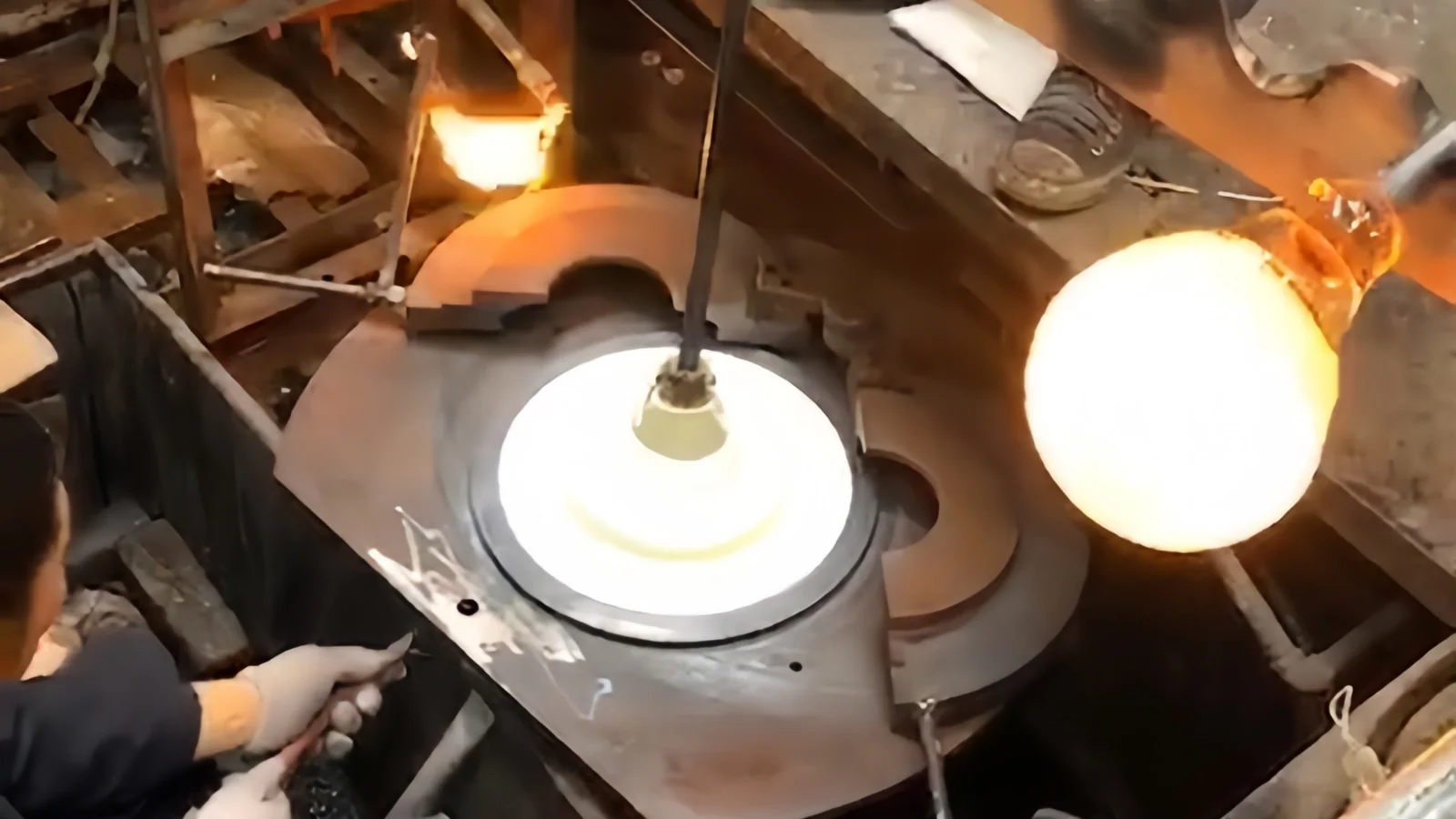
Mould-joint appearance depends on construction and forming method. Some processes rotate the glass during blowing to reduce or remove visible seams, so a visible parting line is not inevitable. The Corning Museum of Glass FAQ describes relevant mould-blowing distinctions. Agree where joint-related marks are acceptable and how they will be assessed.
For ribs, texture and lettering, provide profiles, orientation and appearance references. Confirm whether details are formed at final size or undergo further expansion. Evaluate trial parts for definition, consistency and effects on functional surfaces; assess decorative texture under the intended lighting.
8. Establish Datums, Tolerances and Measurement Methods
Choose datums (measurement references) that relate to installation or use. A finished mounting face, neck or standing surface may be more useful than an irregular decorative body.
A lighting globe might use its finished mounting face as an axial reference, its opening for location and a defined body section for alignment. The appropriate arrangement depends on the assembly.
Prioritise dimensions controlling fit, sealing, retention, clearance, orientation, capacity, internal access and installed appearance. Avoid one tight general tolerance across every surface without checking which features need it.
For important measurements, define the plane, support arrangement and evaluation method. Diameter, roundness, runout (variation during rotation about a reference axis) and alignment describe different characteristics; select the characteristic matching the function.
Measure the finished condition after operations that can change dimensions, including annealing, trimming, grinding, polishing and coating. Agree the inspection method during development so supplier and customer evaluate the same requirement.
9. Define Appearance and Permitted Process Marks
Specify both the intended effect and acceptable variation. Define viewing distance, background and whether inspection uses ambient or transmitted light. For lighting products, review the finished component with the intended light source where practical.
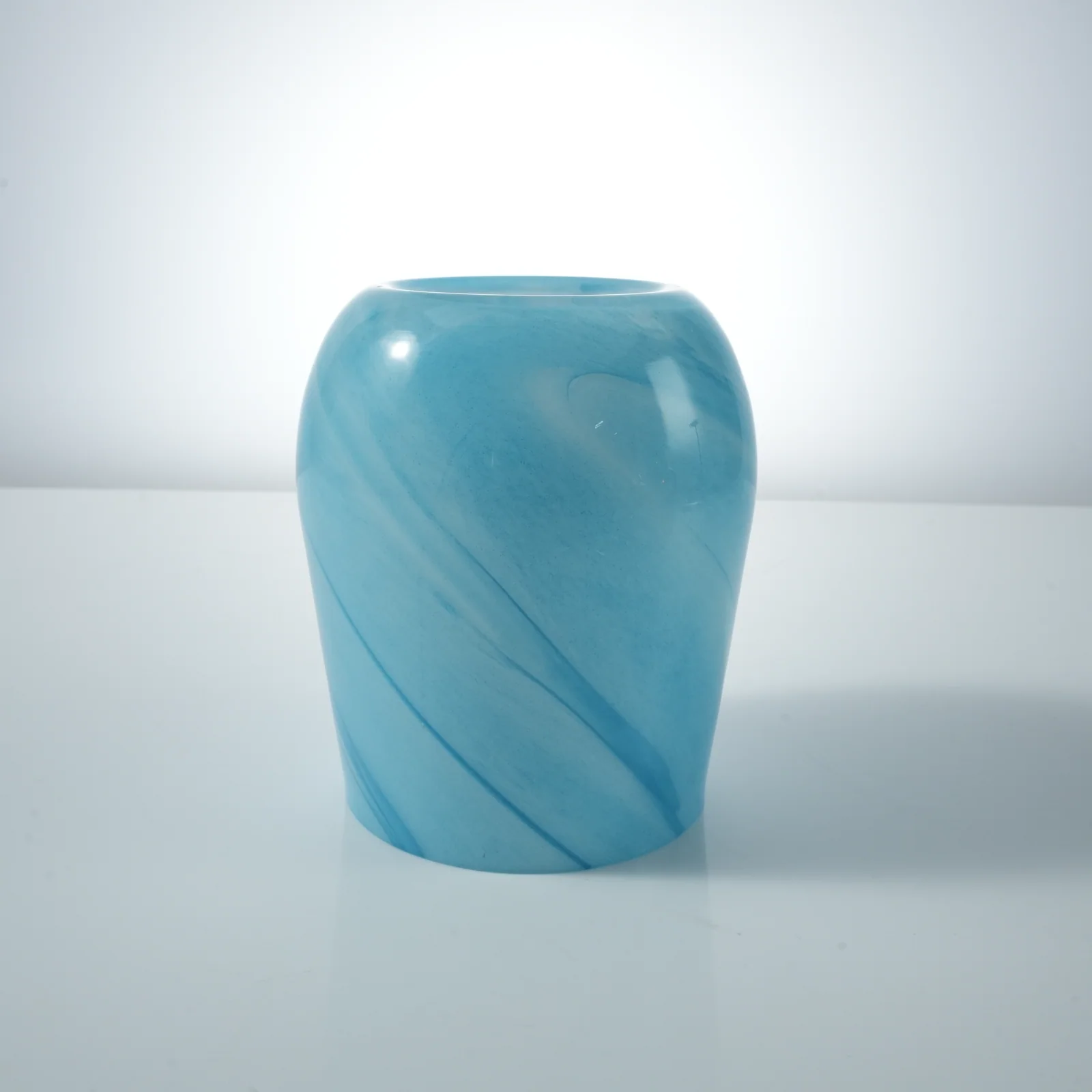
Colour, thickness distribution, texture and decoration should be assessed in the configuration relevant to the customer.
Use a drawing or annotated photograph to distinguish inspection zones. A visible body, concealed mounting region and underside may need different cosmetic criteria.
Reference samples communicate colour, texture and handmade variation. Establish acceptable boundaries as well as a preferred appearance, and distinguish intentional bubbles, texture or asymmetry from unintended defects.
Cracks, damaged functional edges and other specification failures need their own acceptance criteria. A general allowance for handmade variation should not cover them.
10. Plan Annealing and Secondary Finishing
The supplier should establish and validate the annealing cycle, including relevant temperatures and cooling duration, for the selected glass and component geometry. Provide intended use and acceptance requirements for this review. Account for heavy bases, applied features and section changes, and agree support during treatment where it affects the finished condition.
Residual-stress assessment provides evidence about the result. Excessive residual stress can combine with service loads and contribute to failure. MO-SCI's explanation of glass annealing provides background on the thermal process.
For cutting, grinding and polishing, identify each surface and provide sufficient material. Agree tool and workholding access, locating references, material removal, final edge condition, minimum remaining thickness and protection of adjacent surfaces. Not every formed surface can be accessed or supported in the same way.
Define the sequence around decoration, coated and uncoated areas, masking boundaries and dimensions that apply after coating. Include any additional heating in the production review. Final inspection should assess the condition supplied.
11. Agree Sample Approval, Acceptance and Packaging
Give each development stage a clear purpose. An early sample may establish silhouette; a later sample may verify finished dimensions, assembly and decorated appearance. Production approval should refer to the completed specification and the route intended for supply.
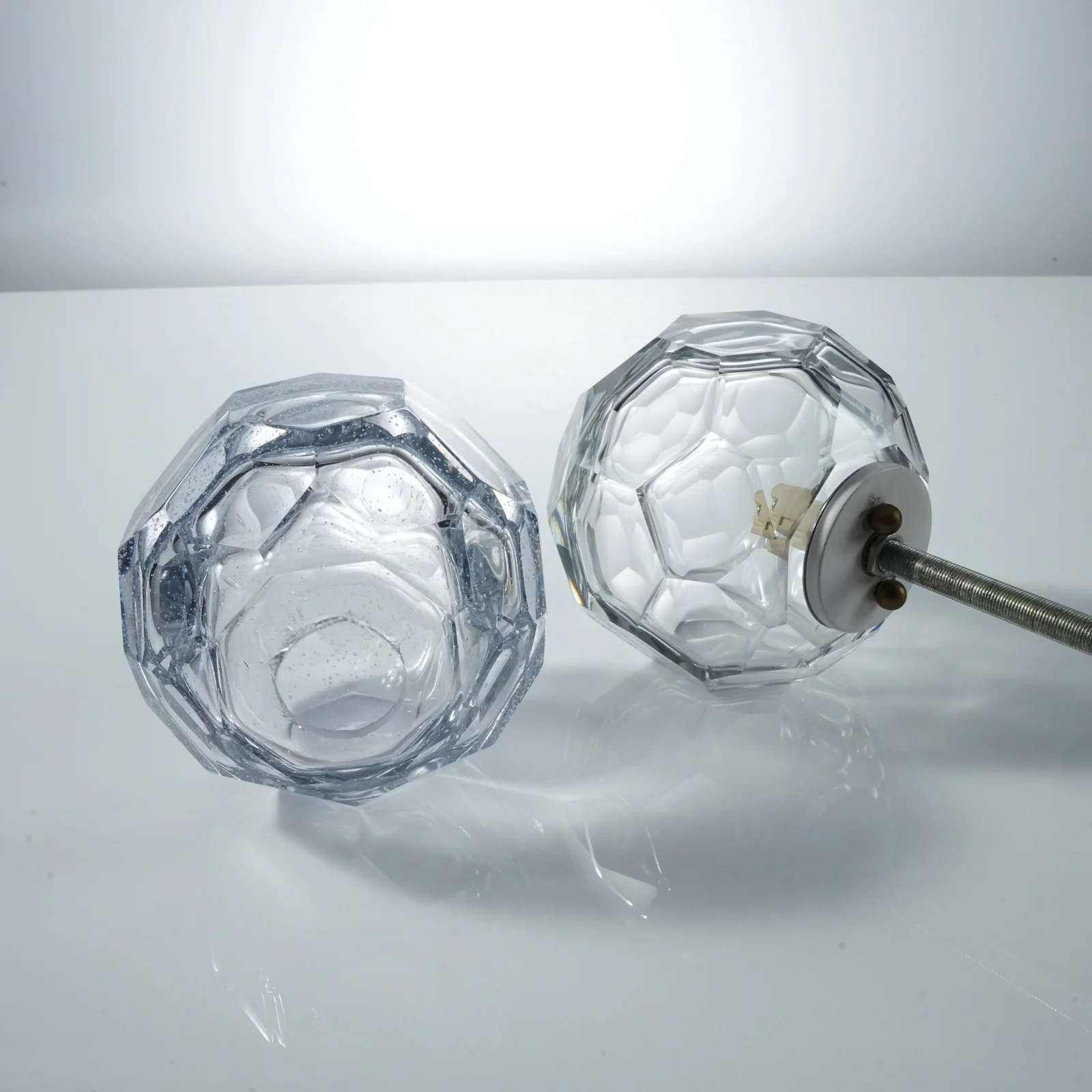
Record deviations and their accepted limits. Use representative samples to assess relevant variation in dimensions, wall distribution and appearance, with assembly or performance checks in the final configuration where required.
Illustrative Pendant Shade Specification
The following example illustrates how to organise requirements; it is not a completed BO-Glass project or a statement of manufacturing capability.
Swipe horizontally to view all columns.
| Feature | Requirement to agree |
|---|---|
| Body | Drawing defines the profile; approved references define permitted handmade variation. |
| Mounting opening | Finished opening and seating face must fit the supplied holder throughout agreed limits. |
| Mounting zone | Define local minimum thickness and the method used to inspect it. |
| Body wall | Specify inspection locations and assess distribution under the intended light source. |
| Edge finish | Drawing defines the finished profile; functional damage has separate acceptance criteria. |
| Appearance | Establish colour, illuminated appearance and limits for visible process marks. |
| Sample approval | Check dimensions, actual holder assembly and final appearance together. |
Dimensions, limits and inspection methods must be agreed for the specific design.
Packaging and Documentation
Specify contact protection, restraint, identification and presentation. Consider exposed rims, protrusions, finished surfaces and attached parts when reviewing packing samples. Agree required inspection reports, traceability and test evidence alongside product acceptance.
12. Submit Your Design for Review and Quotation
Send BO-Glass your drawing, reference sample or concept images, together with the intended application and expected quantities. Highlight the features that determine acceptance: mounting fit, rim geometry, local thickness, capacity, standing stability, colour and appearance.
Include revision information, material restrictions, mating-part details, finish, acceptance criteria, documentation and packaging requirements. Mark unresolved decisions for discussion.
Shape complexity, tooling, critical interfaces, secondary finishing, decoration, quantities and inspection requirements all belong in the quotation review. These details provide the basis for discussing the manufacturing route, tooling, sample development and production supply.
References
- Corning Museum of Glass — Frequently Asked Questions: background on glassmaking and mould-blowing processes.
- Bullseye Glass — TechNotes 3: Compatibility of Glasses: thermal expansion, viscosity and compatibility.
- MO-SCI — Glass 101: Glass Annealing: annealing and residual-stress background.
Contact Us
Discuss Your Custom Glass Project
Share your drawing, photos or dimensions, together with the intended use and target quantity. We will review your requirements and discuss the next steps.
Sales Enquiries
Email sales@bo-glass.com with your part description, intended use and target quantity.
Send Your Design
Use the form to upload a drawing or describe an existing part. Mark critical dimensions and tell us which surfaces or features matter most.
Request a Custom Glass Quote
Upload a drawing or share dimensions, quantity, intended use and finish. Include any heat, pressure or chemical exposure.
Your drawings remain confidential.
We use the contact details you provide to respond to your enquiry. See our Privacy Policy for more information.