
Annealing, Finishing and Quality Inspection of Blown Glass
A blown component is ready for approval when its thermal treatment, finishing and inspection establish the required supplied condition. This guide helps designers, engineers and purchasing teams connect product requirements with manufacturing controls, suitable test methods and traceable release evidence.
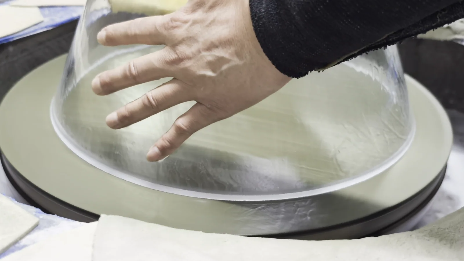
Quick-start: define these five items
- Glass identity, drawing revision and the condition in which the component is supplied.
- Critical geometry, local thickness, finished edges and assembly interfaces.
- Thermal-treatment requirements and the evidence used to assess residual stress.
- Appearance, decoration, optical behaviour and application tests.
- Sampling, rework, cleaning, packaging and batch-release requirements.
1. Define the Finished Condition and Acceptance Plan
Start with the product after every specified operation. A blown opening can change during grinding; fire polishing can change its profile; a coating can alter appearance, transmission and fit. Identify which drawing requirements apply after each treatment and which establish final acceptance.
The customer defines use, interfaces and acceptance criteria. The manufacturer establishes and validates the thermal and finishing routes, then supplies evidence from methods suited to the glass and geometry.
Swipe horizontally to view all columns.
| Requirement | Evidence to define |
|---|---|
| Geometry and fit | Final dimensions, measurement references, supports and mating-part checks |
| Glass distribution | Local wall and base thickness locations and inspection method |
| Annealing quality | Applicable residual-stress assessment and acceptance criteria |
| Edges and surfaces | Required profiles, permitted damage and treatment condition |
| Appearance and optics | Viewing conditions, reference limits and measurements where specified |
| Application performance | Test method, sample configuration and pass/fail criteria |
Keep intermediate checks identifiable. Inspecting a clear body before frosting may help detect defects, but it does not approve the final frosted appearance.
Use reference samples to communicate workmanship and visual variation alongside documented measurable limits. A preferred sample alone does not define permissible opening variation, local thickness or mounting fit. Record method editions and sample condition so future production can be assessed on the same basis.
Map each finishing operation to the requirements it can change. Where a later treatment conceals a surface, plan the necessary earlier examination and the separate final checks. This makes approval a review of the completed route rather than a collection of results taken at incompatible stages.
2. Develop Annealing for the Glass and Geometry
Regions cooling through different temperature histories can retain residual stress. Annealing uses controlled thermal treatment to reduce residual stress, followed by cooling that limits its redevelopment while preserving the required shape.
Develop the cycle for the actual composition and component. Nabertherm's annealing overview identifies glass type and geometry as factors governing the cycle. Review thick bases, narrow necks, substantial rims, handles, solid feet and transitions, rather than relying only on nominal body thickness. A material's listed annealing point supports development but does not prescribe a complete programme.
Swipe horizontally to view all columns.
| Thermal stage | Objective | Conditions to establish |
|---|---|---|
| Entry or reheating | Bring the component to the required starting condition | Incoming thermal state, heating approach and support |
| Equalisation and stress relaxation | Establish suitable conditions across the relevant sections | Temperature distribution and effective holding conditions |
| Controlled cooling | Limit retained residual stress | Profile appropriate to the glass and geometry |
| Further cooling and unloading | Reach the defined handling condition | Remaining temperature differences and removal criteria |
Direct transfer from forming and reheating a previously cooled component have different starting conditions. Account for that difference when qualifying the route, including the supporting fixtures and subsequent operations.
A completed furnace programme does not prove that every component meets its residual-stress requirement. Likewise, remaining intact after cooling is an observation, not an annealing-quality result.
Annealing does not correct wall distribution, remove inclusions or establish repair of an existing crack. Thermal tempering and chemical strengthening are separate processes. Specify any strengthening requirement independently, with its own suitability review and verification; an annealed component should not acquire an unsupported strength rating.
3. Control Loading, Cooling and Unloading
Record the transition from final hot working, including delays, temporary holding and additional heating. Establish loading orientation, support contact and spacing to preserve shape and permit the intended heat transfer.
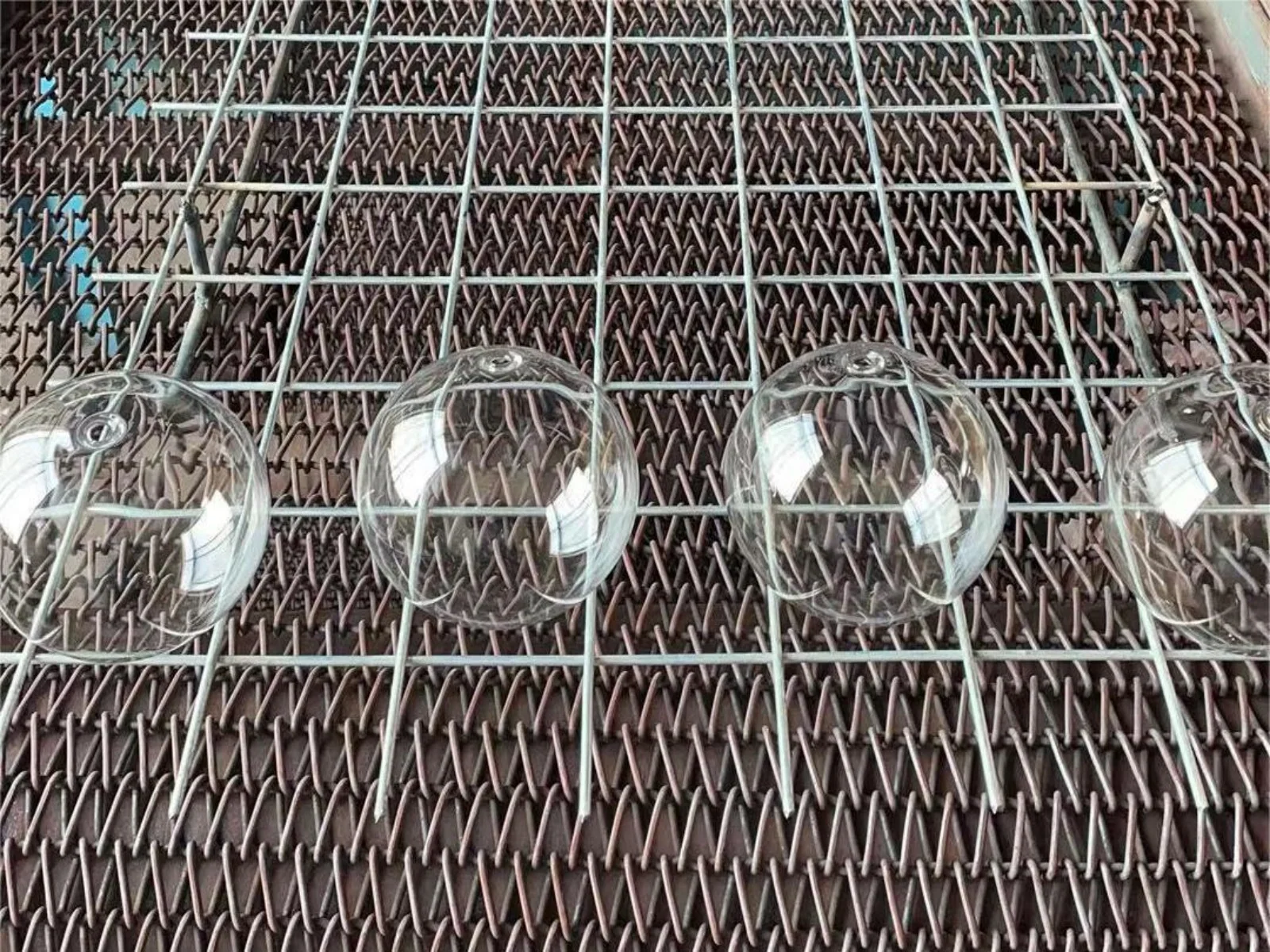
For batch equipment, define loading completion and how holding relates to the last pieces introduced. Where a continuous lehr is used, identify loading pattern, speed and zone profile. Apply these controls to the actual installation rather than assuming one arrangement fits every furnace-blown product.
A controller reading describes its sensor location, not the temperature throughout every piece. Qualification should assess representative loads and positions, including combinations of product sizes where these are permitted. Use the results to establish routine checks and loading limits.
The cooling instruction must continue beyond the hold. Define the stages, ventilation or door-opening conditions, removal endpoint and support after unloading. Thick bases or attached features can retain different temperatures from thin walls; lower-temperature gradients can still cause damage.
Identify loads affected by power loss, interruption or departure from the profile. Record the event and determine the evaluation needed before release. A return to normal equipment settings does not automatically establish the condition of glass exposed during the interruption.
4. Verify Residual Stress with a Suitable Method
Polarised-light methods can assess annealing quality in suitable glass products. Define whether the requirement uses visual observation, comparison with references or quantitative measurement, and verify that the method can examine the region of interest.
ASTM C148 addresses polariscopic examination of glass containers made from commercial soda-lime-silica compositions. Confirm applicability before using it for another composition or product. Its optical-retardation results require interpretation for the particular ware; referencing the method does not make every geometry suitable for the same interpretation.
Swipe horizontally to view all columns.
| Method record | Information needed |
|---|---|
| Procedure | Standard or validated method, edition and instrument |
| Examination region | Location, orientation and viewing arrangement |
| Optical path | Applicable thickness and geometry information |
| Reported result | Quantity, units and interpretation used |
| Acceptance | Limit or reference comparison and decision rule |
| Instrument control | Verification, reference checks and suitability evidence |
Optical retardation is not directly interchangeable with a stress value. Hinds Instruments explains the relationship between birefringence, thickness, the material's stress-optic coefficient and differential stress. Interpretation also depends on geometry and stress distribution; report the measured quantity accurately and establish the basis for any conversion.
Consider bases, rims, neck transitions and attachment regions according to the design. Strong colour, opal glass, texture or coatings may restrict examination. An obscured region or unclear pattern should not be recorded as an acceptable result merely because no defect can be distinguished.
Where the selected method cannot assess a required region, resolve the limitation in the inspection plan. If a coating prevents later optical examination, establish what evidence will represent the completed thermal route. A result taken before subsequent firing does not establish the post-firing condition simply because the finished surface is difficult to inspect.
Residual-stress assessment also remains separate from checks for cracks, chips, dimensions and application performance.
5. Plan Cutting, Grinding and Edge Finishing
Plan material removal before forming. Coldworking may include cutting, grinding, polishing, drilling, engraving or sandblasting after cooling. The Corning Museum of Glass process overview illustrates several glassworking operations, including grinding and hand sanding. The formed shape needs sufficient allowance for the required operation while preserving final wall and base requirements.
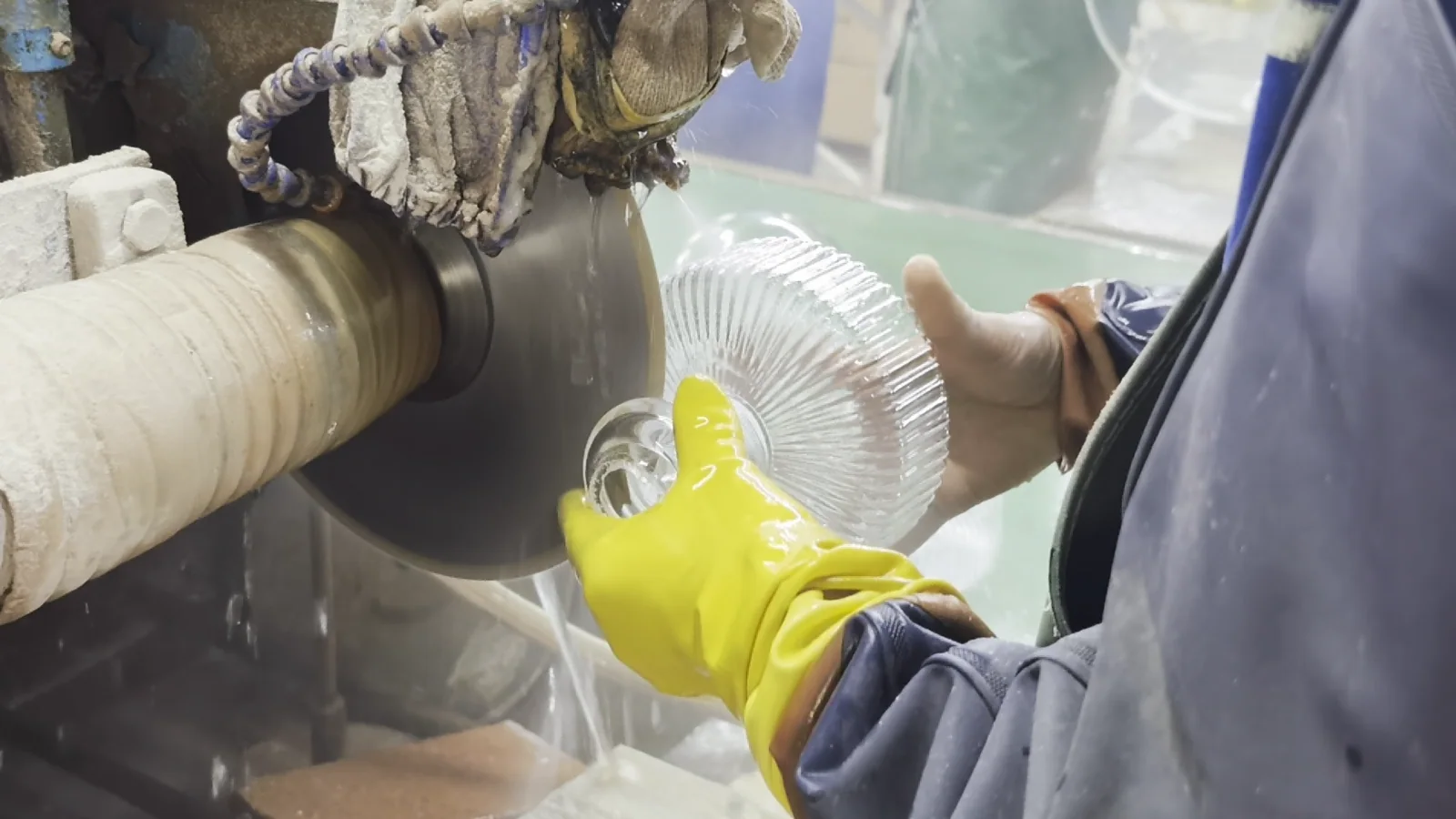
Identify locating surfaces, supports and the measurement reference for each critical cut or ground face. Review access, abrasive and tool condition, cooling, cleaning and the effects of applied force on thin walls. Keep intermediate and final drawings consistent with the removal allowance.
A shade's ground rim may establish its mounting plane; a vessel's rim may affect closure or drinking contact; a finished base may control rocking. Define the edge profile and function as well as gloss.
Inspect inner and outer edges, transitions and the points where machining begins or ends. Check for cracks, chips, uneven removal and unacceptable marks. A shiny edge alone does not establish an acceptable structural condition.
Place inspections where they can reveal the relevant defect, including before later decoration conceals a surface. Control removal so polishing does not silently consume the allowance or alter a previously approved interface. Record rework that changes geometry and identify the checks needed afterwards.
6. Review Fire Polishing and Surface Treatments
Fire polishing reheats glass to smooth superficial irregularities and can also alter local geometry. Review opening diameter, rim profile, edge radius, thickness and alignment against the final drawing, especially where a seal or holder depends on the surface.
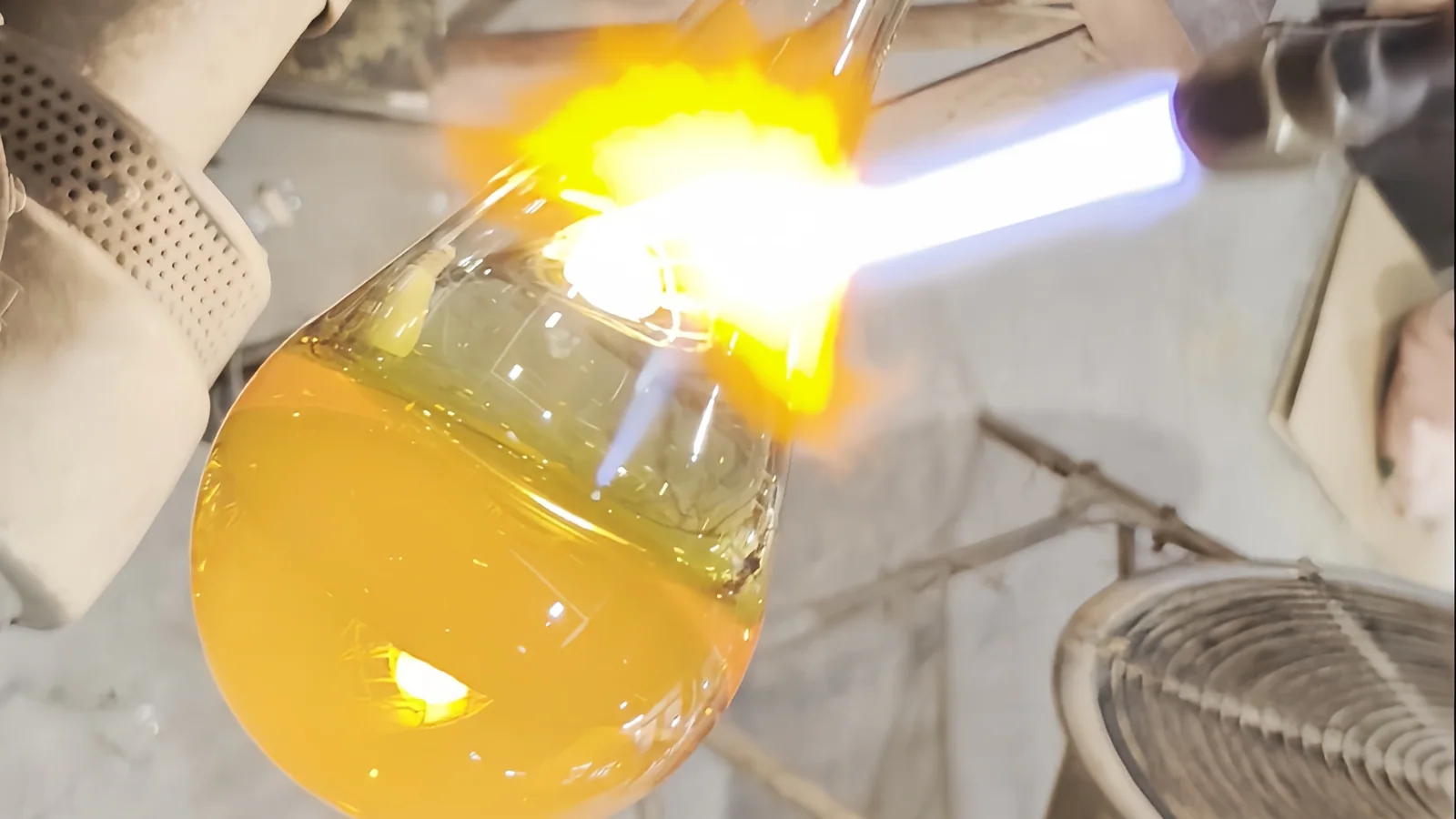
Additional heating after annealing requires review of subsequent treatment and cooling. The earlier annealing record does not demonstrate the residual-stress condition after fire polishing, fired decoration or another thermal operation. Compatibility of joined glasses or vitreous decoration remains a separate requirement; additional annealing should not be assumed to resolve an incompatible combination.
For frosting or sandblasting, define the treated side, texture, coverage and clear-area boundaries. For paint, metallisation or other coatings, establish colour, gloss, uniformity, masking, pinhole criteria and adhesion or thickness checks where needed. Connect durability requirements to the intended cleaning and service conditions.
Specify artwork position, orientation and registration for printing or decals, together with the appearance after curing or firing. Inspect treatment on the production geometry: a flat test panel may not represent a deep, curved or recessed surface.
Check buildup on seats, openings and threads where it can change fit. Retain treatment-batch and curing or firing records with the component's thermal and finishing history.
7. Check Dimensions, Wall Thickness and Assembly Fit
Inspect the supplied condition after operations capable of changing a requirement. Define measurement references, support and method for critical dimensions rather than relying on an unrestricted general tolerance.
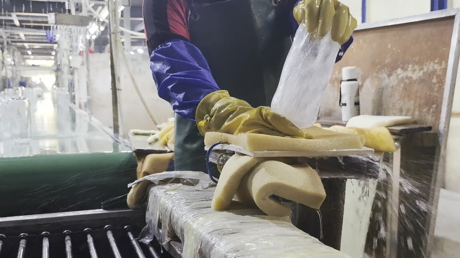
Checks may include overall profile and height, opening diameter and ovality, rim flatness and orientation, base support, hole location, neck alignment and mounting interfaces. Position the glass without forcing it into an artificial shape or seating condition.
Weight, thickness and geometry provide separate evidence. Equal weights can conceal different distributions; an acceptable exterior does not establish internal clearance. Define wall and base measurement locations around the actual design. A single value or average may miss a critical thin region.
Select a thickness method suited to the material, curvature and accessible surfaces. State whether results describe individual positions, minimum values within a defined region or another specified quantity.
Use controlled mating components or gauges for fit, with the relevant gasket, seating and fastening conditions. A successful insertion alone may not establish location, retention or sealing. Include installed orientation and service conditions where they influence the interface.
Retain measurement context with results, including part identification and the finishing or coating condition represented. A dimension recorded before a final treatment should not silently substitute for a final acceptance measurement.
8. Define Appearance and Application Tests
Appearance and Optical Behaviour
Set lighting, background, viewing distance, orientation and inspection zones. For lighting components, include the intended illuminated assessment where appearance in use matters.
Define limits for bubbles, cords, seams, tool marks, texture and visible attachment areas. Intentional effects need their own range: a seeded design does not imply acceptance of any bubble population. Keep cracks and damaged functional edges outside a general allowance for handmade variation.
For measured colour or transmission, specify method, location, thickness and treatment condition. Identify spectral range, measurement geometry and whether transmission is direct or total. Material-sheet values do not establish the result for a curved, textured, frosted or coated component.
Application Performance
Select tests for the actual exposure and function. Establish method and edition, sample quantities, configuration and acceptance criteria before testing.
Swipe horizontally to view all columns.
| Evaluation | Conditions to define |
|---|---|
| Thermal shock or cycling | Starting conditions, medium, exposure sequence, transfer and cycles |
| Impact | Location, support, impactor and acceptance endpoint |
| Pressure or leakage | Applicable pressure difference, duration, fixture and seal |
| Assembly | Mating parts, gasket, fastening and operating conditions |
| Cleaning or chemical exposure | Agent, concentration, temperature, duration and permitted change |
| Coating durability | Conditioning, method and acceptable loss of function or appearance |
Represent the specified frame or mounting where performance depends on the assembly. State whether a report covers material specimens, an individual glass component or the complete assembly. Material properties support design but do not establish a finished-product rating: geometry, surfaces and test exposure also matter.
9. Control Cleaning, Packaging and Batch Release
Cleaning should remove abrasive, polishing residue and contamination while preserving glass and decoration. Review chemistry, water quality, rinsing and drying, including narrow openings and recesses. Inspect for residue, fingerprints and water marks before protected handling and storage.
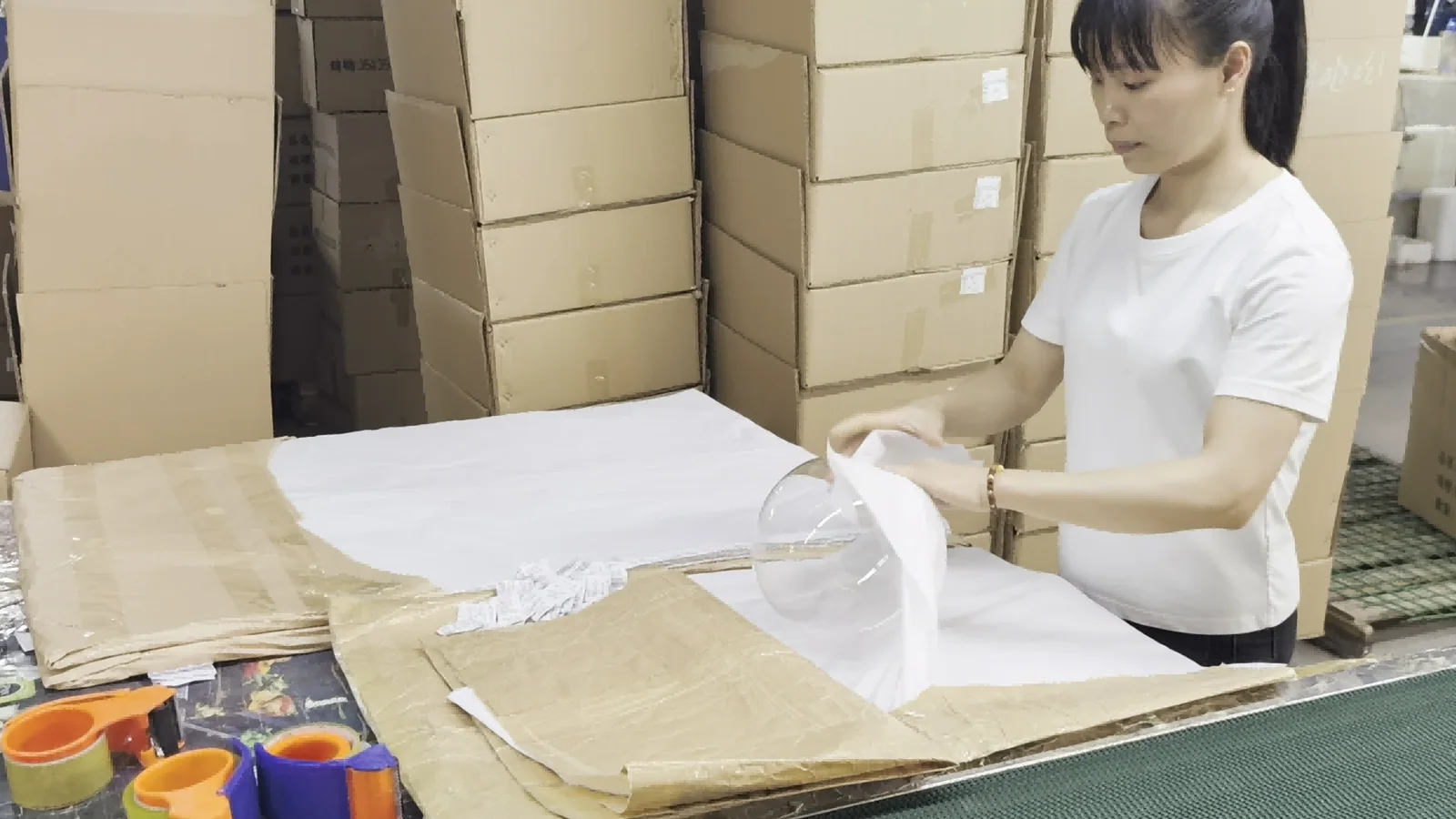
Packaging must protect rims, projections, interfaces and visible surfaces from adjacent pieces, concentrated loads, movement, abrasion and loose particles. Maintain product and batch identification. Where distribution performance is specified, assess the packed product for the intended route; passing product inspection does not prevent subsequent handling damage.
Define lots and how samples represent time periods, moulds, annealing loads, finishing equipment and treatment batches. Distinguish development qualification from routine release. Establish characteristics inspected, sampling or full inspection, defect classes, acceptance/rejection rules and actions following failure.
If an acceptance-sampling plan is used, record its basis and decision rules. Sampling supports a lot decision; it does not establish that every item is defect-free. Set the inspection approach around the requirements and consequences of the defects concerned.
Identify and keep failed or uncertain production separate pending disposition. Define permitted rework and reinspection: grinding, reheating or recoating can affect requirements that previously passed. Link reworked pieces to their original lot and repeat affected checks before release.
The approval record should connect drawing revision, materials, forming and tooling, annealing loads, finishing and decoration, inspection and test results, deviations and packaging. Preserve samples and production history when breakage needs investigation rather than assigning a cause from appearance alone. Release the batch against the completed evidence and retain the decision with its lot identification.
References
- MO-SCI — Glass 101: Glass Annealing: controlled thermal treatment and residual-stress reduction.
- Nabertherm — Annealing/Cooling Glass: dependence of the thermal cycle on glass type and geometry.
- Corning Museum of Glass — Process and Properties Video Clips: background examples of glassworking operations.
- Corning Museum of Glass — Fire Polishing: reheating to smooth superficial irregularities.
- ASTM International — C148-17(2022): published scope of the glass-container examination methods.
- Hinds Instruments — Stress Measurement: relationship between optical measurements and differential stress.
Contact Us
Discuss Your Custom Glass Project
Share your drawing, photos or dimensions, together with the intended use and target quantity. We will review your requirements and discuss the next steps.
Sales Enquiries
Email sales@bo-glass.com with your part description, intended use and target quantity.
Send Your Design
Use the form to upload a drawing or describe an existing part. Mark critical dimensions and tell us which surfaces or features matter most.
Request a Custom Glass Quote
Upload a drawing or share dimensions, quantity, intended use and finish. Include any heat, pressure or chemical exposure.
Your drawings remain confidential.
We use the contact details you provide to respond to your enquiry. See our Privacy Policy for more information.