
Manufacturing and Design Guidelines
Molten Glass Pressing
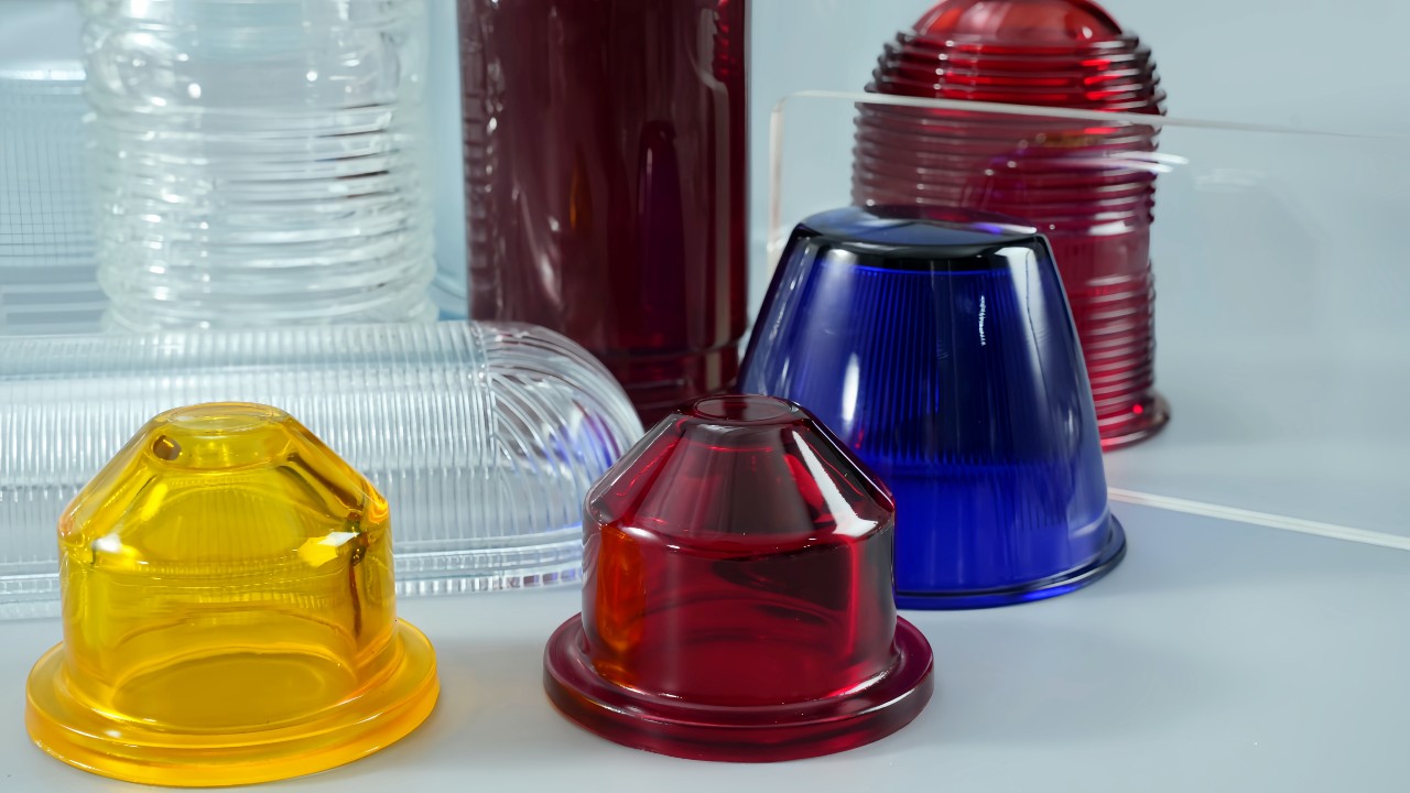
A practical starting point for designing, specifying and sourcing custom components made by direct molten-glass pressing.
Molten glass pressing shapes a measured charge of hot, viscous glass between a mould and plunger. It can reproduce profiles, ribs, prisms and textures for lighting, tableware and technical components. Suitability depends on the glass, geometry, release arrangement and requirements of the finished part.
Use this overview to choose the questions to resolve, find the relevant detailed guide and agree what a supplier must demonstrate before production.
Explore the Six Detailed Guides
Choose a guide by the decision or production issue you need to resolve. Together they cover design, glass delivery, tooling, forming, annealing and troubleshooting.
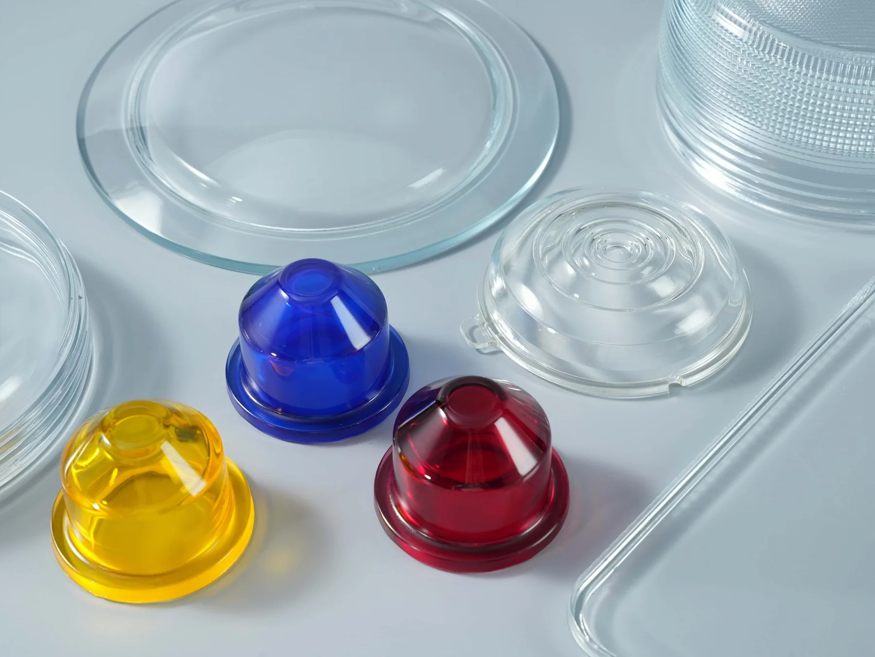
1. Product Design and Forming Feasibility
Review pressing direction, draft, undercuts, wall transitions, rims, threads and optical features. Use this guide when preparing a drawing or deciding which surfaces need finishing.
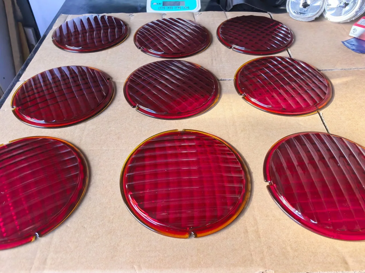
2. Glass Selection and Gob Control
Connect service requirements with glass composition, melt condition, gob weight, shape and delivery. Use it to specify the glass or investigate variation shared by several moulds.
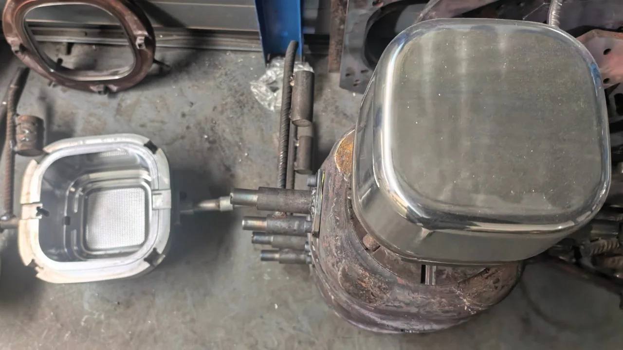
3. Mould Design and Thermal Management
Review the cavity, plunger, rings, alignment, venting, surfaces and thermal controls. Use it when assessing tooling proposals, release problems, wear or maintenance.
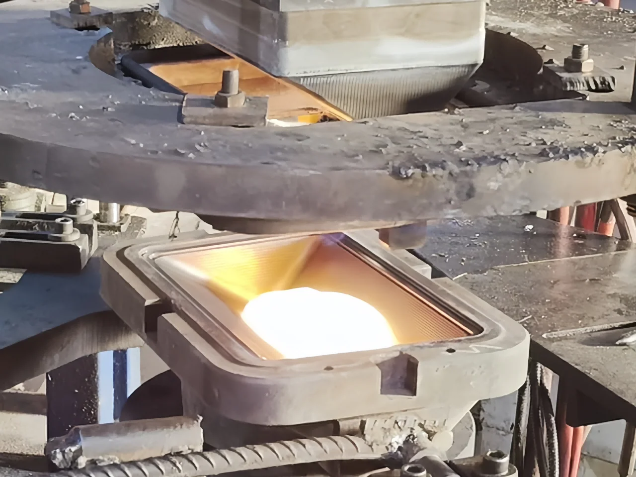
4. Pressing Process Control
Follow gob loading, filling, contact time, withdrawal and handling. Use it to review stage transitions, process records and the conditions supporting a proposed operating range.
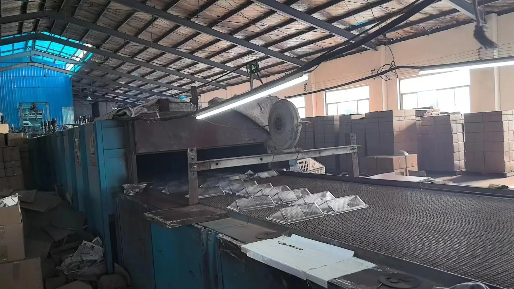
5. Annealing and Quality Inspection
Connect thermal history with stress, dimensions, appearance and function. Use it to define inspection conditions or assess results after annealing and finishing.
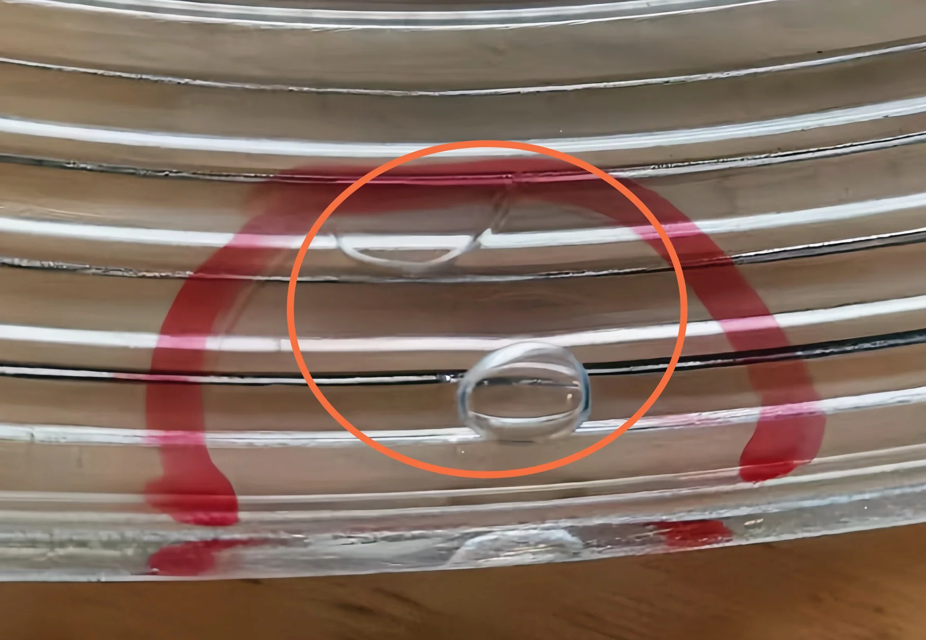
6. Defects and Troubleshooting
Identify the observed feature, trace its distribution and test a cause. Use it to plan containment, corrective trials, related quality checks and restart verification.
Decide Whether Pressing Fits the Part
Begin with the final component: its function, assembly interfaces, delivery state and acceptance requirements. An overall size that fits a press does not establish that a local undercut can release or an optical feature will meet its performance requirement.

Review three questions together:
- Can it be formed and released? Check plunger access, pressing direction, draft, undercuts, parting interfaces, local thickness, corners and air escape paths.
- Can the selected glass meet both service and process needs? Identify the actual grade or the material properties to be resolved. Specify body colour, opacity and surface treatments separately.
- Which requirements need subsequent processing? Mark ground mounting faces, drilled holes, polished areas, coatings or strengthening. Agree allowances and the stage at which each tolerance applies.
A broad opening may permit direct plunger withdrawal. Restricted openings, enclosed hollow shapes and deep undercuts require specific tooling assessment or consideration of another forming route.
Swipe horizontally to view all columns.
| Route | When to assess it | Key distinction |
|---|---|---|
| Direct molten glass pressing | A molten gob can be distributed and released through the proposed tooling | Review filling, local thickness, tool access, release and annealing |
| Glass blowing | A hollow body can be shaped by inflating hot glass | Review wall distribution, openings and shape control |
| Press-and-blow forming | A pressed intermediate shape is subsequently blown | Both forming stages and transfer must suit the product |
| Reheat pressing | An existing glass charge is reheated for forming | Charge preparation and thermal history differ from direct melt delivery |
| Precision glass moulding | Prepared optical preforms are shaped with precision tooling | Preform quality, surface replication and thermal effects are central |
| Cutting, grinding and polishing | Glass stock or blanks can be machined, or formed parts need finishing | These operations may be a primary route or part of a pressing route |
SCHOTT TIE-40 describes prepared-preform precision moulding and contrasts it with conventional reheat pressing. It is referenced here to distinguish routes, not to specify the capability of direct molten-glass pressing.
Tooling investment should be assessed alongside glass availability, annealing, finishing, inspection, product variants and expected repeat demand. Compare the cost and delivery of an accepted finished component under the same specification.
Follow the Process from Glass to Finished Part
The equipment may be manual, mechanised or automated. Agree the actual route and who is responsible for each operation; an equipment example does not establish a supplier's capability for a particular part.
- Prepare and condition the glass. Control the specified material, melt quality and thermal condition for delivery.
- Form and deliver the gob. Establish the available glass quantity and the shape, orientation and loading position entering the mould.
- Press and form the surfaces. Coordinate plunger motion, force, tool thermal condition, air escape and contact time.
- Release and transfer. Match separation, supports and handling contacts to the component's condition. Include hot finishing only where specified.
- Anneal and cool. Apply a thermal route suited to the glass, section thickness, geometry and loading arrangement.
- Finish and verify. Perform the specified secondary operations and confirm acceptance at the required final stage.
Automated equipment can connect feeding, pressing and handling through to the annealing lehr; WALTEC's pressing systems provide an equipment example. The detailed guides above explain the individual control points.
Glass Delivery in Practice

The forming route begins with glass in the required condition at the mould. Specify the relevant delivery and handling conditions for the equipment being used, rather than assuming all pressing lines use the same feeding arrangement.
Define Quality and Acceptance Requirements
Turn the intended function into repeatable inspection decisions. A requirement such as “clear”, “smooth”, “low stress” or “good fit” needs defined conditions and a measurable limit or approved reference.
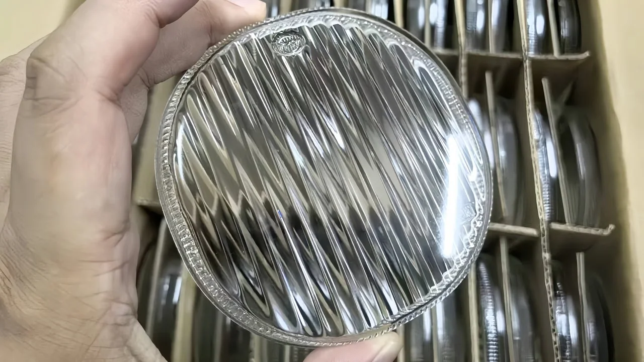
Record the drawing revision and delivery state. Tool dimensions do not transfer directly into final cold-part dimensions without the effects of forming and cooling; requirements after grinding, polishing or coating may also differ from those for a pressed-and-annealed blank.
Swipe horizontally to view all columns.
| Characteristic | Conditions to agree |
|---|---|
| Dimensions and profile | Datums, inspection locations, supports, temperature condition and applicable tolerances |
| Thickness distribution | Measurement positions, minimum sections and a method suited to the geometry |
| Appearance | Inspection zones, illumination, viewing distance, orientation and identified reference samples |
| Bubbles, inclusions and edge damage | Feature definitions, size, count, permitted locations and detection method |
| Residual stress | Reported quantity, orientation, light path, measurement arrangement and acceptance limit |
| Transmission and colour | Wavelength or source, thickness, surface state, collection geometry and required result |
| Optical and assembly function | Source position or mating parts, component orientation, fixtures, loads and performance criteria |
| Thermal or mechanical exposure | Exposure, loading, supports, test sequence and failure criteria |
Match Inspection to the Application
For lighting lenses, refractors and covers, separate optical zones from mounting areas and permitted mould marks. Evaluate prisms and textures with the intended source position and component orientation.
For tableware and decorative parts, specify rim quality, base stability, appearance and intended use. Include relevant stacking, cleaning, decoration and service-exposure requirements in the validation plan.
For technical components, focus on sealing faces, holes, threads, contact surfaces and applied loads. Use a representative assembly where supports, gaskets or fasteners affect the result.
Temperature changes are a service condition that may apply to any of these groups. Define the actual exposure and mounting arrangement; a material name or a temperature-difference figure alone is insufficient to specify finished-part performance.
Distinguish Material Data from Finished-Part Results
Internal transmittance excludes surface reflection losses. Finished-component measurements also depend on thickness, surfaces, geometry and coatings; a textured part can redirect light outside a detector's collection area. SCHOTT TIE-35 explains the material-transmittance distinction.
Agree sampling across relevant moulds, stations, thermal-process positions and production periods. Define the response to an unacceptable result, including containment and further inspection. Reference samples support appearance assessment; they do not replace dimensional or functional criteria.
Prepare a Comparable Quotation and Supplier Review
A quotation should identify both the customer's requirements and the supplier's proposed scope. Mark assumptions and open decisions so a provisional proposal is distinguishable from a confirmed production commitment.
Swipe horizontally to view all columns.
| Customer provides | Supplier confirms |
|---|---|
| Application, environment and operating conditions | Proposed route, service-related questions and validation needs |
| Drawing / model, revision and critical features | Forming and release assessment, proposed design changes and features requiring trials |
| Required glass grade or functional material needs | Proposed grade, availability and any material decisions still open |
| Surface, optical and assembly requirements | As-formed versus finished surfaces, processing sequence and measurement approach |
| Acceptance limits and reference samples | Inspection methods, sampling proposal and reports included |
| Development quantity, order quantity and repeat demand | Trial scope, quantity basis, production assumptions and stage-specific lead times |
| Delivery state, packaging, identification and schedule | Included delivery controls, documentation and dispatch assumptions |
Ask for evidence relevant to the proposed component: identified trial parts, measurements tied to the agreed specification and results after the required finishing operations. A photograph, equipment list or single acceptable sample alone does not establish repeat-production capability.
Align Scope, Cost and Timing
Separate tooling, development trials, samples, production parts, secondary processing, inspection reports and delivery preparation. Identify what is included, excluded or subject to trial results.
Clarify tooling ownership, storage, maintenance and modifications. Agree which operations the supplier performs and which are provided through other facilities, with responsibility for quality and traceability defined across the complete route.
Record when each quoted lead time starts: for example, after drawing approval, material confirmation or sample acceptance, as agreed for that project. Compare quotations using the same quantity, specification, inspection scope and finished delivery state.
Agree Packaging and Delivery

Specify protection of critical surfaces, part separation, cleanliness, identification and required documentation. Review the proposed packaging against the actual component and transport conditions rather than treating a generic packing photograph as an approved specification.
Approve Development in Stages
Use evidence at each stage to close the relevant decisions. The sequence below is a planning framework; agree the checks, sample coverage and approval responsibilities for the project.
Swipe horizontally to view all columns.
| Stage | Evidence to review before proceeding |
|---|---|
| Feasibility review | Defined drawing and material basis; proposed forming / finishing route; unresolved features and trial objectives |
| Tool and forming trials | Identified tooling, recorded conditions, filling and release results, thickness distribution and surface formation |
| Annealing and finishing verification | Stress, dimensions, appearance and affected function checked at the specified delivery stage |
| Representative production trial | Results covering relevant positions, running periods, restarts and loading arrangements under recorded conditions |
| Production approval | Accepted evidence, agreed inspection / release plan, controlled production basis and remaining actions explicitly resolved or authorised |
Plan the Verification Before Changing the Process
Set the decision criteria, relevant sample coverage, observation period and related quality checks before the trial. Define how process readiness will be recognised and account for the delay before changed production reaches inspection.
A part produced immediately after an adjustment may reflect a transition. Likewise, parameters individually inside stated limits do not demonstrate that every combination has been shown to work. Connect the operating conditions actually tested with the resulting part measurements.
When a trial fails, record the defect's location and distribution, preserve suitable samples and investigate a specific explanation. Verify a correction against the original issue and other characteristics it could affect. The troubleshooting guide provides the detailed investigation sequence.
Keep Repeat Orders and Changes Under Control
Retain the approved basis for future production: product revision, material, tooling identity and condition, glass delivery, pressing stages, thermal route, finishing and inspection plan.
Keep four records distinct:
- Target settings: intended normal operating conditions.
- Validated conditions: the parameter combinations and configurations supported by acceptable results.
- Alarm and stop conditions: departures requiring intervention or interruption.
- Product acceptance limits: the requirements the supplied parts must meet.
The manufacturer's controlled records may hold detailed recipes. Agree which sample approvals, inspection reports and traceability information accompany the customer's order.
Review material substitutions, tooling repairs, cooling changes and added finishing operations before extending an earlier approval. Define the affected production, required checks and release decision; update the controlled record when the changed condition has been demonstrated.
For repeat orders, confirm the current drawing, acceptance requirements, quantity and delivery state against the approved basis. Identify the checks needed after a restart or extended tooling storage.
Start a Custom Pressed Glass Project
For a technical review or quotation, send BO-Glass the drawing or model, application, material requirements, critical dimensions, surface expectations and planned quantities. Include optical, thermal, mechanical or assembly criteria, required finishing and delivery conditions, and any decisions still open.
This information supports a defined discussion of the forming route, tooling, development samples and inspection scope for the proposed component.
Contact Us
Your feedback fuels our growth, and your questions drive our solutions.
We value your feedback, inquiries, and suggestions. Please feel free to get in touch with us
General inquiries
Please contact us via sales@bo-glass.com, and we will reply to you as soon as possible.
Interested to work with us
Drop your resume at info@bo-glass.com
and we will get back to you shortly.
We uses the contact information you provide to us to contact you about our relevent content, products, and services.