
Pressed Glass Defects and Troubleshooting
A practical guide to identifying defects, narrowing the investigation and verifying corrective action in molten-glass pressing.
A short rim, surface line or broken edge can have several causes. Effective troubleshooting connects what is visible with the part location, production history and measurements, then tests a specific explanation. The place where a defect is first detected is not necessarily where it originated.
Defect Triage and Location Mapping
Start with this investigation sequence, then use the symptoms below to choose the next check.
- Isolate suspect parts
- Preserve samples
- Map and trace
- Verify corrective action
Select a symptom to open its checks. Swipe horizontally to see all columns.
| Observed symptom | Establish this distinction first | Investigation |
|---|---|---|
| Short rim, missing rib or weak detail | Overall glass shortage or local distribution / replication problem? | Incomplete filling |
| Line, crease or overlapping surface | Gob-related fold, shear mark or replicated tool feature? | Shear marks and folds |
| Recurring roughness or unwanted texture | Fixed to a tool location or changing with process conditions? | Mould marks |
| Drag, stretch or damage during release | Which contact and which release movement produce the feature? | Sticking and release |
| Parting-line step, flash or irregular rim | Alignment mismatch, excess projection or later edge damage? | Parting lines and rims |
| Variable mass, thin area or off-centre shape | Total glass quantity or uneven distribution? | Mass and thickness |
| Bubble-like feature, pit or solid inclusion | Internal void, open surface feature or solid material? | Bubbles and inclusions |
| Streaks or distorted transmitted image | Internal variation, surface geometry, thickness or stress? | Cords and striae |
| Haze or colour change | Surface condition, bulk glass, coating or measurement setup? | Haze and deposits |
| Crack, check or chipped edge | Fracture origin and first affected stage, rather than detection stage alone? | Cracks and chips |
| Rocking or poor assembly fit | Part deformation, local projection or datum / fixture issue? | Warpage and fit |
| Stress indication or later breakage | Residual stress, local damage or a combination? | Stress and breakage |
| Optical or functional failure | Material, geometry, surface condition or test configuration? | Functional checks |
Record a reproducible location
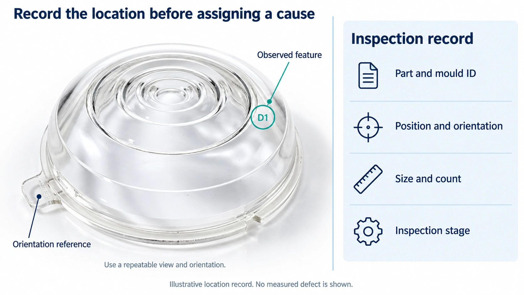
Assign a defect code and record size, count, surface or depth where established, position and orientation relative to a repeatable datum. Photograph the feature with a scale under controlled lighting; keep acceptable comparison parts and untreated affected samples.
Link each sample to its lot, glass outlet or feeder, mould / plunger / station, production time, annealing lane where applicable, finishing history and inspection stage. Compare patterns:
| Distribution | Useful next comparison |
|---|---|
| Same position on parts from one mould | Corresponding cavity, plunger, ring and local release contacts |
| Multiple moulds supplied by one outlet | Shared glass supply, gob delivery and timing |
| Several positions after a common change | Shared settings, utilities, material or inspection changes |
| One annealing lane or support pattern | Loading, supports and thermal history |
| First detected after finishing or assembly | Retained parts from earlier stages and later contact conditions |
Contain the potentially affected material while investigating. Account for the delay from manufacture to detection and for downstream work, stock and shipments where relevant. Preserve evidence before cleaning, polishing, re-annealing or dismantling a suspect tool.
Incomplete Filling and Poor Feature Replication
Identify. Record whether the feature is a short rim, missing rib, rounded detail or incompletely formed flange. Distinguish insufficient total glass from glass that has not reached or replicated a local feature.
Check. Compare mass at the same production stage. Account for planned finishing removal, actual flash or trim, retained glass on tools and breakage losses where applicable. A lighter finished part does not, by itself, prove an underweight gob. Check gob position and shape, delivery delay, press motion, relevant force or position records, tool thermal condition and the intended vent path.
Verify. Examine the matching cavity feature for wear, deposits or obstruction. Test a focused hypothesis with comparable parts after the process stabilises. Increasing force will not restore worn detail or establish that venting is adequate.
Recheck. Confirm local thickness, dimensions, flash, release behaviour and feature replication across the affected tooling positions.
Shear Marks, Folds and Flow Lines
Identify. Map the line's shape and orientation. Compare it with the gob entry path, initial contact region and corresponding tool surface. Appearance alone may not distinguish a shallow mark from a fold extending below the surface.
Check. Review shear condition, cutting timing and treatment, unexpected transfer contact, rotation or waiting, and how the gob spreads during pressing. Compare parts before finishing so later processing does not obscure the evidence.
Verify. Use suitable magnification or prepared sections when surface observation cannot resolve the feature. Relate a trial to a specific transfer or forming change rather than adjusting several settings together.
Recheck. Confirm both appearance and the relevant structural or optical requirement. Fire polishing that makes a line less visible does not demonstrate that a buried fold has been removed.
Mould Marks and Surface Roughness
Identify. Determine whether the feature repeats at a fixed position corresponding to the cavity, plunger or ring. Intended texture and permitted tooling marks should be distinguished from unwanted replication using agreed inspection zones.
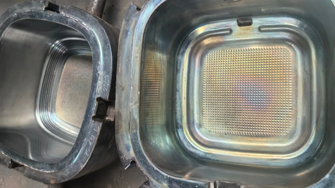
Check. Inspect matching tool areas for machining marks, deposits, treatment condition, oxidation, wear or thermal-fatigue cracking. Compare clean and established-run conditions, tooling positions and relevant temperature / contact-time records.
Verify. Document the surface before and after an approved cleaning or restoration step, then compare replicated parts. Tool restoration can alter radii and dimensions; an improved appearance alone is insufficient.
Recheck. Confirm the drawing, intended texture, release and any optical surface requirements. Mould thermal cycling is one recognised source of tool cracking and transferred surface marks; it does not explain every rough surface. Technical context: Gillinder on pressed-glass moulds.
Sticking, Drag Marks and Release Damage
Identify. Establish whether sticking, stretch, drag or breakage occurs during plunger withdrawal, ring separation, mould opening or take-out. Record the first observed contact and movement associated with the damage.
Check. Review local thermal conditions, surface state, draft and undercuts, alignment, clearances, withdrawal sequence and release treatment. An increased withdrawal load supports investigation but does not identify the cause on its own.
Verify. Observe representative release cycles using an appropriate safe method and compare the part with its contact surfaces. Make a controlled correction and retain evidence of the changed behaviour.
Recheck. Confirm dimensions, distortion and surface condition after annealing. Additional release agent can create deposits or interfere with later coating, so include affected downstream requirements.
Parting-Line Mismatch, Flash and Rim Defects
Identify. Separate a step between mould sections from a thin projection of glass, and both from chipped or damaged edges. Record location, height or thickness where measurable, and whether the feature is continuous.
Check. Review guides, seats, mating-surface cleanliness, matched tool sections and closure. A satisfactory cold fit does not establish the operating clearance. Compare changing flash with gob mass, closure records and relevant forming conditions.
Verify. Check closure and parting-line geometry under the defined trial conditions. If grinding or polishing is permitted, assess the result against a specified finished profile rather than treating removal as proof that the forming issue is resolved.
Recheck. Confirm rim strength-related requirements, safe handling, seal contact, mating fit and adjacent damage as applicable.
Uneven Thickness, Weight Variation and Off-Centre Forming
Identify. Measure mass and thickness separately. A part can have acceptable total mass while retaining a locally thin wall or asymmetric distribution.
Check. Use a fixed thickness map referenced to drawing datums, including minimum-thickness areas and transitions. Compare gob entry position and shape, tooling alignment, motion and thermal behaviour. Separate as-formed variation from material removed during finishing.
Verify. Use a measurement method suited to the curved surface and local access. Machine position is not a direct measurement of the hot tool gap: thermal expansion and system compliance may affect the relationship.
Recheck. Compare cold dimensions, thickness distribution and mass at a consistent stage, then confirm the affected mounting, mechanical or optical function.
Bubbles, Blisters, Stones and Inclusions
Identify. Establish whether the feature is a gas-filled void, solid inclusion, surface pit or open blister. Record its size, position and relationship to surfaces or interfaces; a photograph may not establish depth.
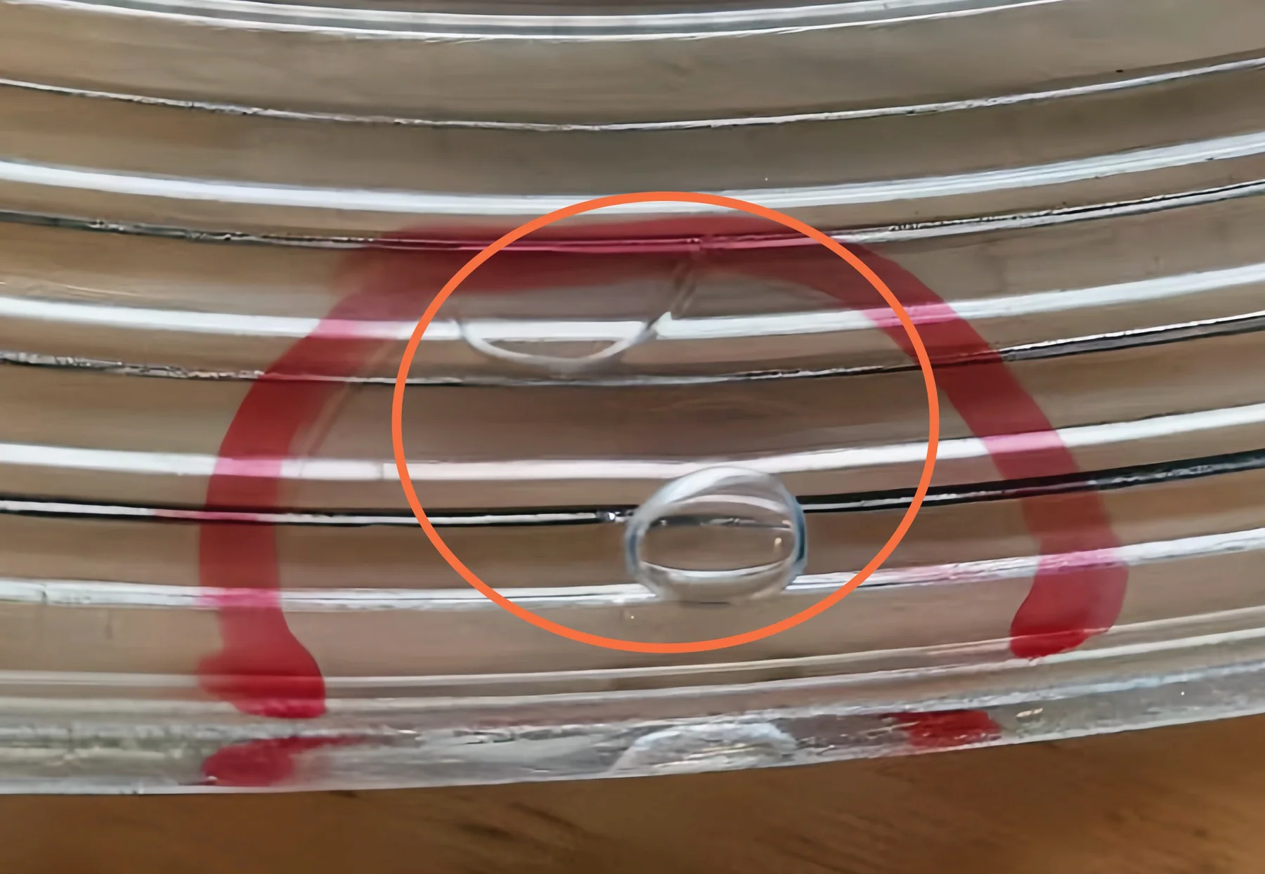
Check. Compare distributions across lots, glass outlets and moulds. Consider melt-origin bubbles separately from air entrapped during forming. For solid inclusions, investigate relevant raw-material, cullet, refractory or crystallisation sources without assigning one from colour alone.
Verify. Preserve representative samples. Depending on the question, suitable microscopy, prepared sections, composition / phase analysis or bubble-gas analysis may be needed. Interpret laboratory findings alongside production records. Technical reference: Glass Service defect analysis.
Recheck. Apply agreed size, count, position and functional criteria, including affected optical or structural zones. Pressing adjustments or annealing should not be assumed to eliminate solid inclusions or existing internal bubbles.
Cords, Striae and Optical Distortion
Identify. Distinguish internal optical inhomogeneity from surface-form error, thickness variation and stress effects. Visibility can change with the viewing direction and optical path.
Check. Compare reflected and transmitted views, surface profile and thickness. Consider glass homogeneity and upstream history when the evidence indicates an internal feature; do not diagnose striae from a distorted image alone.
Verify. Select an optical method appropriate to the geometry, such as a suitable shadowgraph, interferometric assessment or prepared sample. The intended optical power of a curved component must be accounted for.
Recheck. Confirm performance through the specified aperture and orientation in the finished condition. Optical-glass classifications provide technical context, not automatic acceptance limits for every pressed component. Technical reference: SCHOTT TIE-25, Striae.
Haze, Discolouration and Surface Deposits
Identify. Locate the change in the surface, bulk glass or coating, and check that it is not caused by lighting or measurement setup. Retain an untreated reference.
Check. Compare parts before and after release treatment, annealing, washing, finishing and coating. Review residues, contamination, chemical attack and possible crystallisation where supported by the evidence.
Verify. Use a controlled cleaning comparison to test a removable-residue hypothesis. Persistent haze does not by itself establish crystallisation; further examination may be needed. Compare colour and transmission under consistent illumination, path length and collection conditions.
Recheck. Confirm appearance, specified optical performance and, where relevant, coating adhesion and surface compatibility.
Cracks, Checks and Chipped Edges
Identify. Preserve affected parts, fragments, orientation and fracture surfaces. Record the apparent origin and local contacts where identifiable. Damage first found after annealing may have originated earlier.
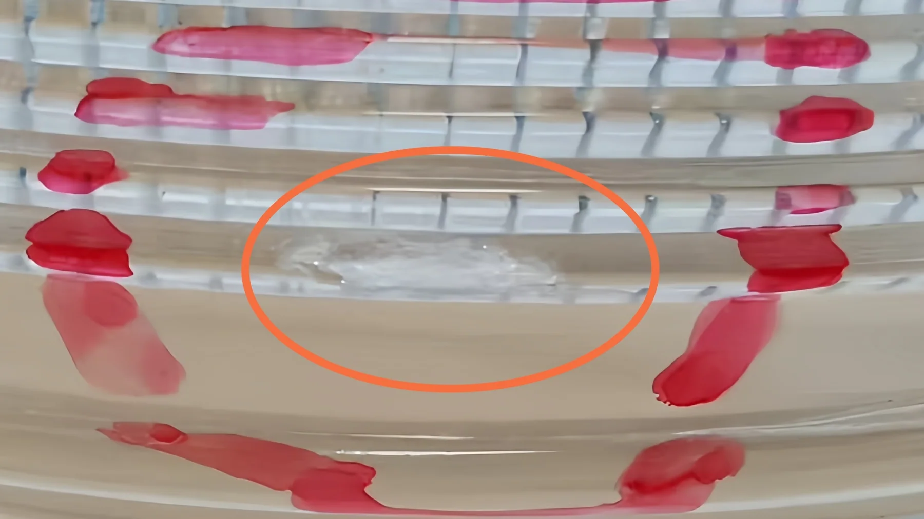
Check. Trace release, transfer, conveyor contacts, thermal history, machining, packing and assembly loads. Compare retained samples from successive stages. Both mechanical damage and thermal stress may contribute.
Verify. Use fracture examination when visual checks cannot establish the sequence or origin. Test the suspected source and inspect comparable parts after the relevant downstream operations.
Recheck. Annealing does not heal an existing crack. Removing a chip does not demonstrate that adjacent cracks or strength-reducing damage have been removed. Release requires the agreed requirements to be met. Technical context: SCHOTT TIE-32, Thermal loads on optical glass.
Warpage, Rocking Bases and Assembly Misfit
Identify. Before diagnosing warpage, distinguish deformation from a local projection, uneven support ring, contaminated fixture or incorrect datum contact. Measure under defined support and temperature conditions.
Check. Compare forming, take-out, annealing and finishing stages. Review mass distribution, release state, support positions, thermal history and unequal material removal. Check mating components and gaskets when the issue appears only in assembly.
Verify. Measure the relevant profile or flatness against the agreed datums and evaluate the intended assembly. A single outside diameter cannot establish the required fit.
Recheck. Confirm free-part geometry and assembled function. Forcing a distorted component into place may introduce stress even if the assembly can be closed.
Residual Stress and Breakage After Annealing
Identify. Separate the stress indication from evidence of physical damage. Detection after annealing does not establish annealing as the sole cause.
Check. Review actual product thermal history, entry conditions, loading, lane effects, support contacts, interruptions and thick-to-thin transitions. Compare affected and acceptable production under equivalent inspection conditions.
Verify. Use a stress-inspection method suited to the glass and geometry. Optical retardation, retardation divided by path length and stress in MPa are different quantities. A dark view at one orientation is not proof of zero stress. Technical reference: SCHOTT TIE-27, Stress in optical glass.
Recheck. A controlled re-annealing trial may help evaluate thermal history, but reduced retardation does not make an already damaged part acceptable. Reassess geometry, surface condition, coatings or strengthening where affected.
Transmission, Light Distribution and Functional Failures
Identify. Confirm the actual failed requirement: transmission over a specified wavelength range, light distribution, colour, image quality, sealing or assembly performance.
Check. Separate material behaviour from thickness, surface condition, geometry and the test setup. For curved or textured components, redirected light may miss the detector without being absorbed. Internal material transmission is not the same as finished-part transmission.
Verify. Repeat the relevant test with controlled source, fixture, part orientation and collection conditions, using a suitable reference. Then investigate the dimension, surface, internal feature or assembly condition indicated by the comparison. Technical reference: SCHOTT TIE-35, Transmittance of optical glass.
Recheck. Verify the specified function in the final state, including finishing, coating and assembly where required.
Root-Cause Trials and Corrective-Action Verification
Define a testable hypothesis, record the baseline and identify what result would support or contradict it. A focused change can isolate a suspected cause. Where interacting factors must be studied together, use a planned experiment with appropriate technical support. Method reference: NIST factorial designs.
Set the verification plan before the trial
Agree and record the following before making the change:
- Decision criteria. Define the target feature, its acceptance limit or approved reference sample, and the inspection method used for both baseline and trial parts.
- Coverage. Specify which tooling positions, production periods and running conditions will be checked, together with sample coverage and the observation period.
- Readiness. Define the relevant stability indicators and permitted variation for the glass supply, tooling thermal state and cycle timing. Account for the travel delay to inspection when identifying trial material.
- Related checks. Name the characteristics that must remain acceptable, such as flash, local thickness, dimensions or release behaviour, plus any required downstream checks. Record the disposition if the target defect improves but another requirement fails.
Example: an incompletely filled rib
This is an illustrative investigation, not a reported production result.
- Map and compare. Record which rib, tooling position and production interval are affected. Compare retained parts, gob mass at the agreed stage, local thickness and relevant process records.
- Inspect the suspected mechanism. Check the corresponding cavity and intended vent path. If a restriction is found, record it before intervention. If it is not found, reconsider the hypothesis rather than assuming venting is responsible.
- Make the controlled intervention. Restore the intended vent condition using the approved tool-maintenance method. Preserve the relevant settings and record any unavoidable concurrent changes.
- Allow the response to reach inspection. Account for tool stabilisation, process variation and the travel delay to the inspection point. Keep pre-change and post-change material traceable.
- Evaluate the result. Repeat the same feature inspection with comparable coverage. Confirm flash, local thickness, dimensions and release behaviour. Improvement supports the hypothesis only to the extent that competing explanations have been addressed.
- Check persistence. Repeat verification across the relevant running conditions and a restart where applicable. Define further investigation if the feature returns or another requirement deteriorates.
Keep the counting basis consistent
Record these quantities separately:
| Measure | Counting basis |
|---|---|
| Inspected parts | Number of parts examined using the stated method |
| Nonconforming parts | Parts failing at least one applicable criterion; count each part once |
| Defect occurrences by category | Individual recorded occurrences under a defined counting rule; one part may contribute several |
| Nonconforming-part rate | Nonconforming parts divided by inspected parts |
For example, one part with a crack and two separately counted bubbles is one nonconforming part and three defect occurrences, provided those features fail the agreed criteria. Do not compare these measures as though they were interchangeable. Method reference: NIST proportion of nonconforming units.
Before-and-after comparisons need compatible inspection methods, sample coverage, production stages and operating conditions. Record the observation period and acceptance basis; do not present a small clean sample as proof of sustained control. Investigate the inspection escape mechanism separately from the manufacturing cause.
Rework, Production Restart and Prevention Records
Choose a documented disposition: acceptance against existing criteria, authorised rework, an approved concession where permitted, or rejection. Rework needs defined limits, traceability and verification of the characteristics it can affect.
| Proposed action | Evidence needed before release |
|---|---|
| Cleaning | Target contamination removed; surface, appearance and downstream compatibility acceptable |
| Grinding or polishing | Remaining dimensions and surface integrity acceptable; affected optical or assembly function verified |
| Thermal treatment | Stress response and affected geometry, surfaces, coatings or strengthening reassessed |
| Coating or recoating | Surface preparation, adhesion and specified function verified |
| Sorting | Target features detectable under the validated inspection conditions |
Validate the sorting method
Use retained samples with confirmed target defects and representative acceptable parts, including examples near the acceptance boundary. Define viewing positions, lighting, aids and inspection time. Check consistency between inspectors or repeated assessments, and assess missed defects and false rejections against the agreed reference classification.
A claim of “100% inspection” describes coverage, not guaranteed detection. If the method cannot reliably reveal the target feature, containment and disposition must reflect that limitation.
Close the action with evidence
Restart only against the defined readiness and release criteria. Verify tooling condition and process stability, identify restart material and retain containment until the required downstream results are available.
Keep the defect definition, affected scope, cause evidence, trial conditions, verification results, material disposition and updated controls in the closure record. Assign responsibility and follow-up timing so an improvement is maintained.
For a technical review or quotation, provide BO-Glass with the drawing and revision, application, glass grade if known, marked photographs with scale, affected quantity and production period, first detection stage, acceptance criteria and available samples or inspection records. These details help define the investigation and any manufacturing or rework scope.
Contact Us
Your feedback fuels our growth, and your questions drive our solutions.
We value your feedback, inquiries, and suggestions. Please feel free to get in touch with us
General inquiries
Please contact us via sales@bo-glass.com, and we will reply to you as soon as possible.
Interested to work with us
Drop your resume at info@bo-glass.com
and we will get back to you shortly.
We uses the contact information you provide to us to contact you about our relevent content, products, and services.