
Molten Glass Pressing: Process and Product Design Guidelines
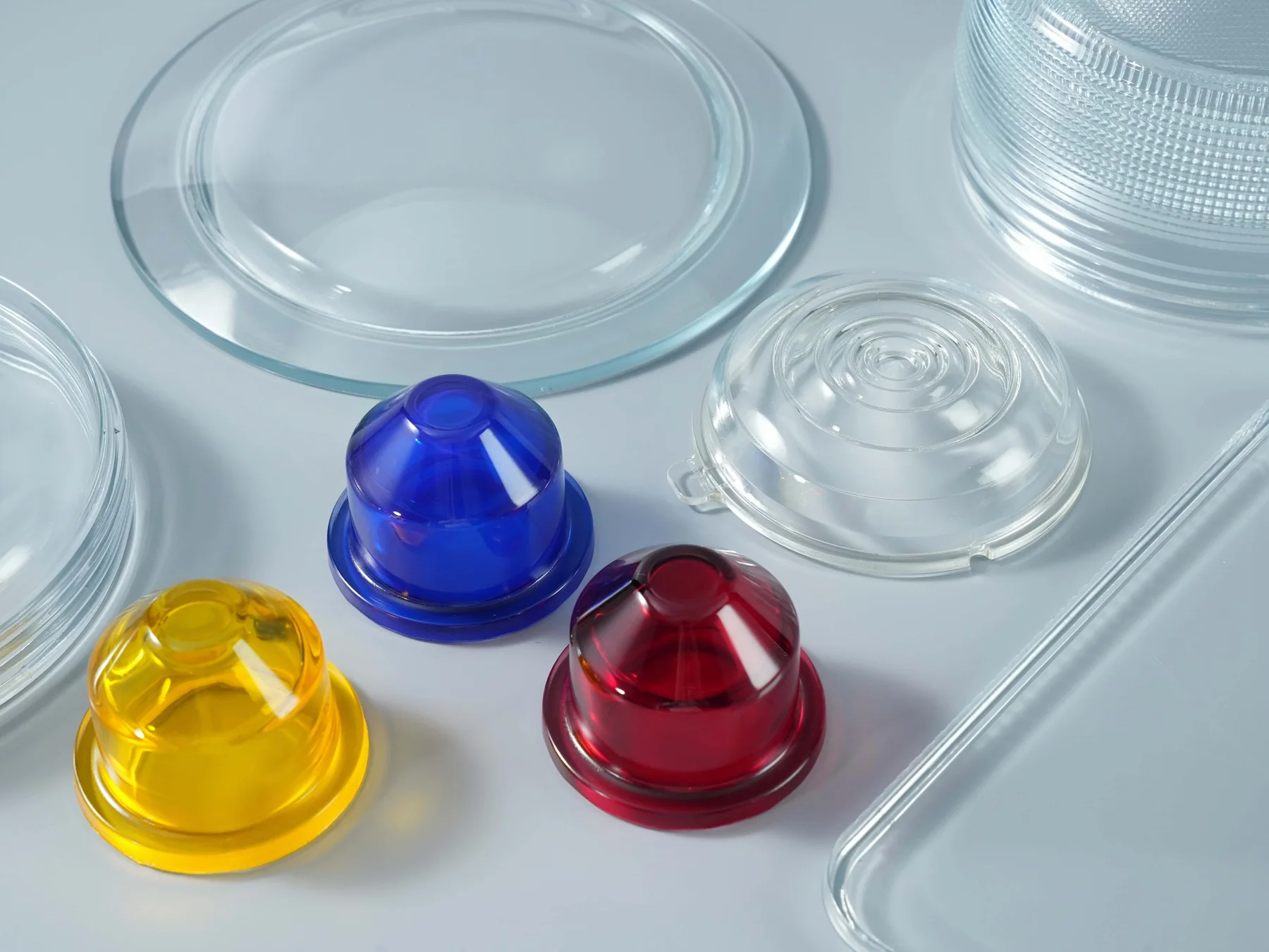
Molten glass pressing forms a measured portion of hot glass between a mould and a plunger. The process can produce the main shape, surface patterns and selected assembly features in one forming operation.
A successful design gives the glass a workable filling path, allows the tooling to withdraw and controls the surfaces that determine performance. This guide explains how to translate those needs into product geometry, drawing requirements and inspection criteria.
How Molten Glass Pressing Works
A gob is a discrete portion of molten glass delivered to the mould. Its mass, temperature distribution, shape and position influence how the glass fills the tooling.
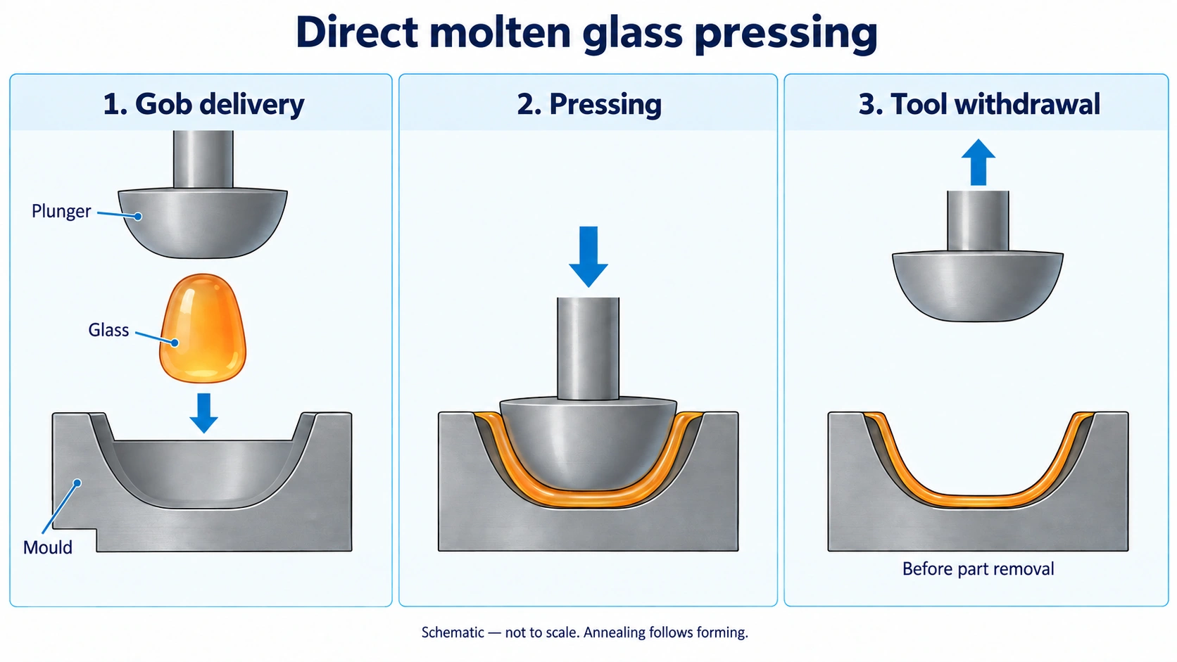
The production sequence typically includes:
- Glass conditioning and gob delivery: prepare the selected glass and deliver a controlled quantity.
- Pressing: move the plunger to distribute the glass into the forming gap.
- Shape stabilisation and release: control tool contact and cooling until the component can be removed and handled.
- Hot-end finishing, where specified: perform operations such as fire polishing.
- Annealing and cooling: manage the thermal cycle to achieve the required residual stress condition.
- Secondary processing and inspection: complete specified machining, treatments and acceptance checks.
Equipment arrangements vary with the product. Industrial lines may integrate feeding, pressing, finishing and transfer through to the annealing lehr. WALTEC: Glass Production Lines
For product design, three questions govern the forming stage: can the glass reach every feature, can each tool section release, and can the part retain its shape during removal and cooling?
Choosing the Forming Route
Start with the complete geometry, including internal surfaces and openings. An open dish and a narrow-neck hollow shade can require different processes even when their outside profiles look similar.
| Route | Geometry or requirement that makes it worth considering | Main design check |
|---|---|---|
| Direct molten glass pressing | Shapes accessible to mould and plunger surfaces, including suitable ribs, prisms and flanges | Filling path, tool withdrawal and surface requirements |
| Blowing or mould blowing | Hollow forms suited to inflation | Wall distribution, openings and finishing |
| Press-and-blow | Hollow articles formed through a pressed preliminary shape followed by blowing | Requirements of both forming stages |
| Spinning or centrifugal forming | Suitable rotational forms | Wall profile, rim geometry and surface condition |
| Reheating and reshaping | Shapes developed from tube, rod, sheet or other existing stock | Starting material and compatibility with the reshaping cycle |
| Grinding and polishing | Precision surfaces or features produced by material removal, often after forming | Stock allowance, access and fixturing |
Press-and-blow includes a distinct blowing stage after preliminary forming and pressing. WALTEC: Press-Blow Machine W-Series
Choose the route against the finished specification. A part that can be pressed may still need grinding, polishing or another operation to meet its functional requirements.
Compare the complete delivered cost
Pressing cost depends on tooling, glass availability, production quantity, cycle time, yield, finishing and inspection. Tooling and trials may account for a large share of development costs; repeat production also depends on tool maintenance and process consistency.
Compare quotations against the same finished specification and order quantity. Establish which tooling, development samples, secondary operations, inspection reports and packaging requirements are included. A difference in unit price may reflect a different manufacturing or acceptance scope.
Selecting the Glass Material
Define the properties needed in service before fixing the material. A glass selected for colour or transmission also needs to suit the proposed forming, annealing and finishing route.
| Requirement | What the specification should establish |
|---|---|
| Optical behaviour | Relevant wavelengths, transmission, colour and, where needed, refractive index |
| Thermal exposure | Operating temperatures, heating and cooling conditions, and contact with surrounding materials |
| Chemical exposure | Contact media, cleaning agents, exposure duration and temperature |
| Mechanical or electrical function | Loads, support conditions and the relevant component or assembly tests |
| Manufacturing compatibility | Suitability for the proposed geometry, tooling and subsequent treatments |
Use a controlled grade or composition where material identity is essential. Where alternatives are acceptable, identify the properties and test results that must be preserved.
Material data also need their measurement conditions. A transmission value requires a wavelength and optical path length; a thermal expansion value requires a temperature range.
Thermal performance must be evaluated with the component geometry and support arrangement. Temperature gradients and differences in expansion between glass and its mounting can introduce stress. SCHOTT: Thermal Loads on Optical Glass
Pressing Direction, Draft and Tool Release
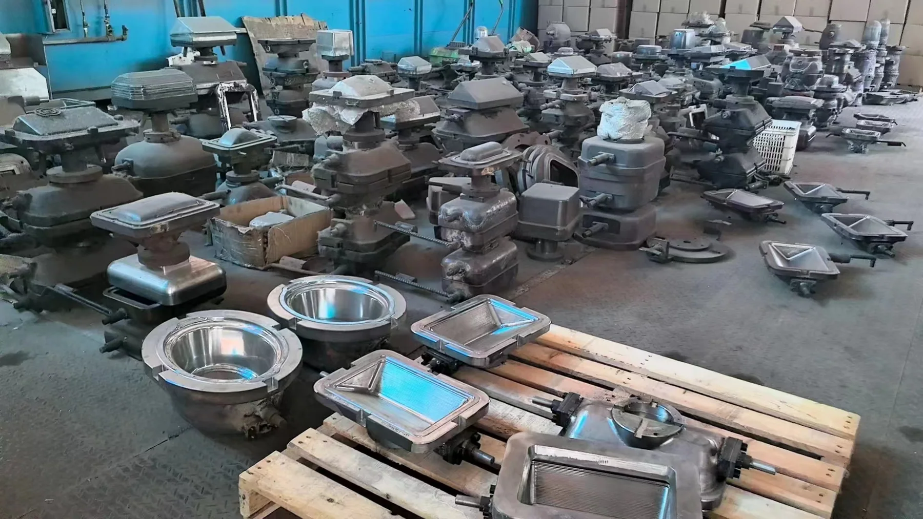
Establish the pressing axis and identify which surfaces are formed by the plunger, mould body, rings and any opening mould sections. Check the full movement from tool entry to withdrawal and product removal.
Check openings and undercuts
A domed cover with an opening narrower than its internal body may trap a rigid internal forming tool. Resolve the release path by adjusting the opening, changing the tooling arrangement or choosing another forming route.
External undercuts may be accessible through opening mould sections. Internal undercuts require their own withdrawal solution. Hinged or split tooling must be assessed against the actual geometry, including local shoulders and projections.
Dimension tapered surfaces at a defined location
Draft assists separation along a release direction. The required taper depends on engagement depth, texture, tool condition and release conditions.
When a tapered surface also locates the part, specify its size at a defined section. For example:
Define diameter D at section S, locate section S by height h from datum A, and show the draft angle and direction.
This establishes where the diameter is measured. Where the housing contacts an extended band, also control the profile or clearance across that band.
Review any draft change on an optical surface against the intended light distribution.
Place tooling interfaces deliberately
Show permitted parting-line locations early. Keep their relationship to sealing faces, locating bands, optical areas and visible surfaces explicit.
Specify a visible seam, a step between mould sections and excess glass at an interface separately. A general note such as “mould marks allowed” leaves their acceptable extent undefined.
Wall Thickness and Section Transitions
Review thickness across the complete section, including rims, bases, ribs and mounting features. Local mass concentrations affect both glass distribution during forming and cooling afterwards.

| Design feature | Potential difficulty | Useful design response |
|---|---|---|
| Thick flange joined to a thin wall | Abrupt change in forming gap and thermal response | Define a gradual transition where function permits |
| Thin edge far from the gob location | Glass must travel through an extended filling path | Review the flow path and edge section together |
| Deep, closely spaced ribs | Restricted filling, air escape and release | Review rib depth, pitch, root geometry and remaining wall |
| Heavy boss on a light shell | Concentrated glass volume and local loading | Review the boss transition and how it is supported |
Preserve thickness variation required for optical power, seating or appearance. Mark those requirements so adjustments to the forming geometry retain the intended function.
For critical regions, provide section views and measurement locations. Distinguish nominal wall thickness, minimum permitted thickness and feature height. On curved surfaces, state whether thickness is measured normal to a surface, along the pressing axis or by another defined method.
Product mass is useful for monitoring material consistency, but it cannot show whether the glass is distributed correctly.
Minimum wall thickness and thickness transitions need validation for the selected glass, flow path and tooling. Use demonstrated process capability when assigning numerical limits.
Corners, Edges, Ribs and Optical Patterns
Use radii and edge breaks that suit filling, handling and the finished function. Define important edges individually: a handled rim, gasket seat and prism apex have different requirements.
For corners and edges, specify the radius or chamfer, tolerance and any envelope that must be preserved. An edge break on a sealing face must leave the required contact width; rounding a prism apex must remain within the optical design allowance.
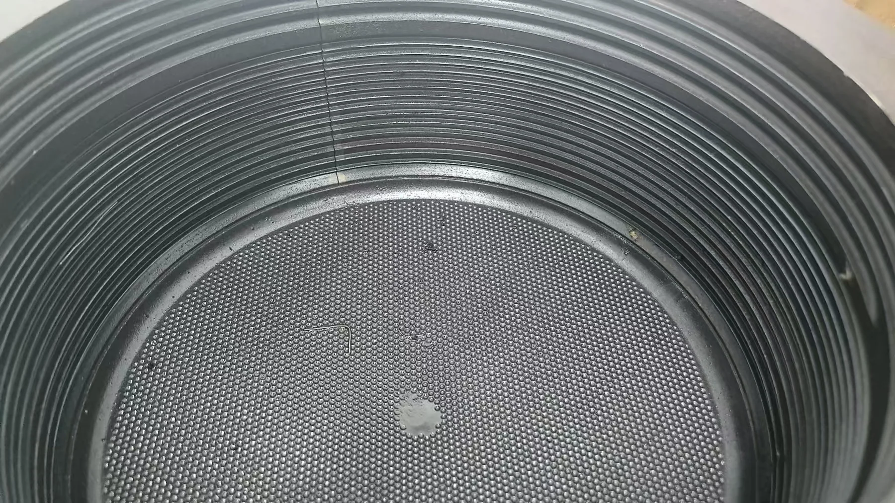
For ribs, prisms and repeated patterns, define:
- Pitch, height or depth, and flank profile.
- Root and crest radii.
- Pattern direction and position relative to mounting features.
- Transition into the surrounding surface.
- The remaining glass section beneath the feature.
Identify whether texture is moulded or added by etching, blasting or another treatment. Show the treated side, coverage boundaries and protected areas.
Accept decorative textures against controlled appearance criteria. For beam-shaping features, connect the geometry to a test using the intended source and component orientation. Terms such as “diffusing” and “anti-glare” need a defined performance metric.
Assembly Interfaces, Datums and Tolerances
Choose reference features from the way the component is supported and located in use. A typical lighting cover may use a seating face for axial position, a locating feature for centring and a notch for angular orientation.
Define contact and clearance
Show the surfaces that support, clamp, seal or locate the glass. Relevant controls include seating-face flatness, flange thickness, locating-feature position, surrounding clearance and gasket compression conditions.
Assess local contact as well as overall fit. A part may satisfy its outside diameter and height while seating unevenly or contacting the housing at an unintended point.
For threads and locking features, specify the profile, pitch, major and minor dimensions, engagement length, entry geometry and any rotational stop. Evaluate engagement and tightening with the defined mating part.
Assign tolerances to the required function
An overall size tolerance does not necessarily control roundness, flatness or surface profile. Give each critical characteristic a nominal definition, reference system, permitted variation and inspection condition.
For freeform surfaces, define the coordinate system, model revision and orientation. State which source governs if the drawing and CAD model contain overlapping requirements.
The inspection support should be defined where seating or restraint affects the result. Measurements on a freely supported part and a clamped assembly may answer different questions.
Keep shrinkage compensation in the tooling definition
The product drawing should describe the finished component. Tooling dimensions then account for the selected glass, forming conditions and finishing allowances.
Validate compensation through trial measurements. A single shrinkage percentage may not describe the relationship between every tool surface and the final geometry.
Clearly identify any model containing tooling compensation so it is not applied again.
Surface Zones and Optical Requirements
Divide the component into zones with explicit boundaries: optical, sealing, locating, decorative and handling areas. Where zones overlap, state all requirements that apply.
| Characteristic | Definition needed for inspection |
|---|---|
| Optical aperture | Evaluated area and location relative to datums |
| Surface form | Nominal geometry, permitted deviation and measurement area |
| Transmission | Wavelength range, optical path, coating state and measurement arrangement |
| Colour | Glass appearance or transmitted-light colour, with source and viewing conditions |
| Light distribution | Source dimensions and position, part orientation and acceptance metric |
| Surface defects | Defect category, size or extent, location and inspection conditions |
For visual inspection, specify lighting, viewing distance, orientation and any magnification. Controlled reference samples can supplement written limits when their identity and applicable features are recorded.
Separate scratches, chips and cracks from permitted tooling impressions. An appearance allowance should not leave the acceptance of damaged glass undefined.
Internal transmittance describes attenuation within the glass and excludes surface reflection losses. Finished-component transmission also depends on surface reflection, coatings and the optical path. SCHOTT: Transmittance of Optical Glass
State whether acceptance applies after pressing and annealing, after optical finishing, after coating or in the assembled condition. Imaging or wavefront requirements require explicit surface and optical specifications; a visually smooth surface is insufficient evidence of compliance.
Internal Quality and Annealing Acceptance
Surface inspection, internal quality and residual stress are separate acceptance subjects. Select the controls relevant to the product and its application.
Bubbles, inclusions and striae
For bubbles and solid inclusions, define the evaluated region or volume, defect-size limits, permitted quantity or concentration, and inspection method. Their optical significance depends on size, distribution and position within the system. SCHOTT: Bubbles and Inclusions in Optical Glass
If striae or optical homogeneity require control, give them a separate inspection or functional acceptance basis. Avoid using a broad appearance term such as “clear glass” to cover every internal characteristic.
Residual stress after annealing
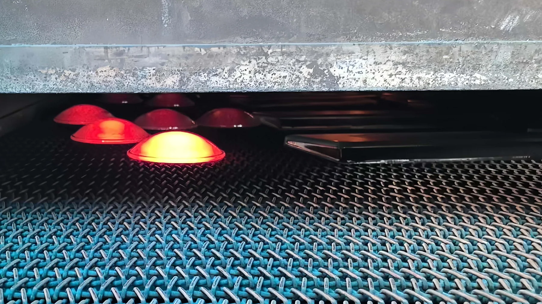
Annealing controls residual stress through the thermal cycle. The result depends on glass type, geometry, size and annealing conditions; stress can also produce birefringence. Polariscopic or polarimetric methods can be used to evaluate stress-related optical effects where suitable for the material and part. SCHOTT: Stress in Optical Glass
Where annealing quality requires verification, establish:
- The test method and evaluated locations or light paths.
- The reported quantity, units and acceptance limit.
- The component condition and inspection stage.
- The sampling plan and required records.
For shaped or coloured parts, confirm that the method provides a usable measurement through the intended region. Treat a qualitative stress pattern and a quantitative acceptance measurement as different results.
If strengthening is specified, define its requirements and inspection stage separately from annealing.
Grinding, Polishing and Subsequent Treatments
Identify secondary operations while the forming geometry is being developed. A ground seating face or polished optical surface needs enough stock to accommodate formed variation while preserving the finished wall and edge dimensions.
For each processed surface, define the final geometry, machining allowance, locating surfaces and adjacent features requiring protection. Check that fixtures and tools can reach the area.
A flange intended for face grinding, for example, needs an allowance on the processed face and a final thickness requirement. The drawing should make clear which dimensions apply before processing and which apply to the finished component.
Fire polishing requires a separate geometry review. Local reheating can soften fine detail or change edge definition, so prism tips, threads and seating features need suitable limits when they are affected.
For coatings, decoration or strengthening, show the treated surfaces, exclusions and final acceptance condition. Place inspections after the operation that establishes the characteristic: a finished seating surface is checked after grinding, and coated optical performance is verified in the specified coating state.
Worked Example: A Flanged Lighting Cover
Consider an open glass cover with a mounting flange and an asymmetric optical pattern. The following example shows how to connect its design features to drawing requirements.
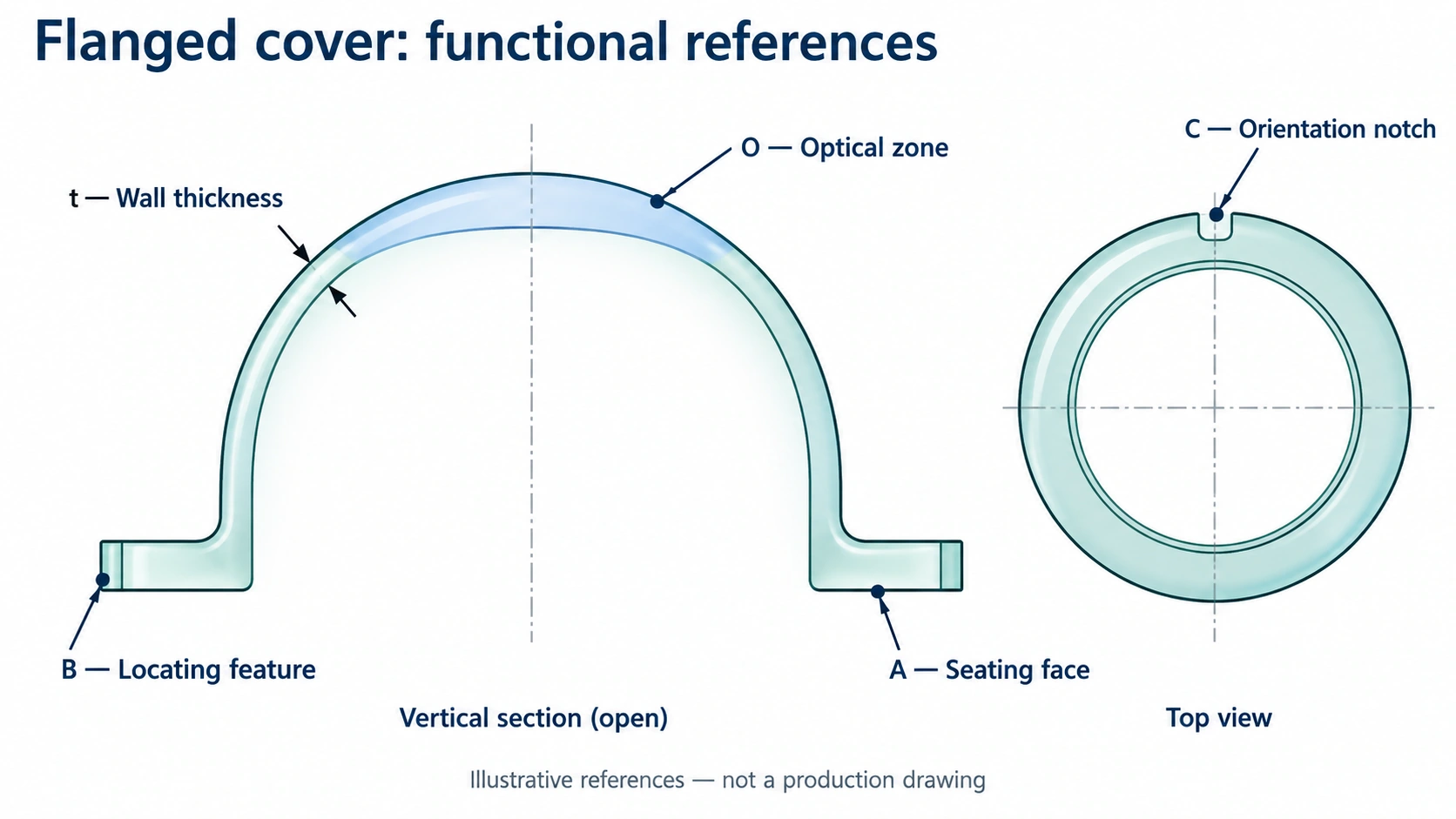
| Feature | Drawing definition | Verification |
|---|---|---|
| Seating face A | Identify the annular contact area and its flatness requirement | Measure the defined area using the specified support |
| Locating feature B | Define its position relative to A and the geometry used for centring | Check size, alignment and mating clearance |
| Tapered locating band | Define diameter D at section S, height h from A, and draft direction | Measure at S and check the contact envelope |
| Orientation feature C | Define angular position relative to the optical pattern | Check pattern-to-mounting alignment |
| Optical zone O | Show aperture, nominal surface data and pattern limits | Inspect geometry and test the specified light distribution |
| Wall sections T1–T3 | Locate each section and define thickness measurement direction | Check nominal and minimum thickness as specified |
| Tooling interfaces | Show permitted locations and limits for seams, steps and excess glass | Inspect each interface against its applicable zone |
| Ground flange face | Define machining stock and final flange thickness | Inspect the finished seating geometry after grinding |
The example provides a structure for a product drawing. Actual dimensions and tolerances come from the assembly requirements, optical design and validated manufacturing capability.
Validating the Finished Design
Development samples should verify the characteristics that determine performance in the final manufacturing state.
For lighting glass, this may include source alignment, transmission, colour and beam distribution. For tableware, priorities may include rim condition, base stability, capacity, stacking and cleaning durability. Technical components may require sealing, thermal, mechanical, chemical or electrical tests under defined service conditions.
Record the drawing revision, material, processing state, test arrangement and acceptance criteria with the results. Use dimensional measurements to refine tooling compensation and functional tests to confirm the design. Incorporate approved changes into the controlled drawing and specification before production release.
Preparing for a Design Review and Quotation
A clear project brief connects the component's function with the proposed forming, finishing and inspection route. The most useful information includes:
- Drawing and CAD model: current revision, units, section views and critical dimensions.
- Application and assembly: intended use, operating conditions, mating geometry and optical requirements where applicable.
- Material requirements: specified glass grade or required properties, including whether alternatives may be considered.
- Finished condition and acceptance: required machining, polishing, coatings, surface criteria, internal quality and relevant tests.
- Production needs: development samples, order quantities, expected annual demand and delivery schedule.
For an existing component, photographs and available inspection results can help explain the design. For an early concept, identify the requirements that must be preserved and the features that remain open to adjustment.
Share these details with BO-Glass to discuss the forming route, tooling concept and any secondary processing needed for your custom pressed glass component. Before tooling approval, agree on the proposed design changes, validation work and specification used as the basis for the quotation.
Contact Us
Your feedback fuels our growth, and your questions drive our solutions.
We value your feedback, inquiries, and suggestions. Please feel free to get in touch with us
General inquiries
Please contact us via sales@bo-glass.com, and we will reply to you as soon as possible.
Interested to work with us
Drop your resume at info@bo-glass.com
and we will get back to you shortly.
We uses the contact information you provide to us to contact you about our relevent content, products, and services.