
← Back to the glass rod pressing technology guide
Precision Glass Moulding Process Control
Precision glass moulding controls how a preform heats, deforms, contacts the mould and retains its shape during cooling and release. Temperature, force, displacement and time act together, with results influenced by preform volume, tooling condition and the glass–mould interface.
This guide connects machine settings and actual process records with finished-component measurements across production runs, material lots and tooling service life. It expands the process-development stage of the Precision Glass Moulding Design Guide.
At a glance: Control the actual thermal condition, contact sequence, forming mode and cooling transition as one connected process. Link recorded temperature, force and displacement to finished-part measurements, and qualify the combinations of conditions used in production.
The scope is optical-surface replication using high-quality preforms and precision tooling; conventional pressings intended for subsequent grinding and polishing follow a different manufacturing route. SCHOTT TIE-40: Optical glass for precision molding
Define the Finished Component Requirements
Process development begins with the optical drawing and acceptance criteria.
Depending on the component, critical requirements may include surface form, clear aperture, centre thickness, edge geometry, centration, wedge, surface roughness, cosmetic quality and functional optical performance. Residual stress or stress birefringence may also require evaluation.
Each requirement needs an appropriate measurement method and clearly stated conditions. Surface-form results depend on the evaluation aperture and fitting convention. Optical performance may depend on wavelength, temperature, mounting conditions and the refractive-index data used in the analysis.
The relationship between process variables and product quality provides a useful starting point for the control plan.
| Control variable | Conditions to record or identify | Associated quality considerations |
|---|---|---|
| Temperature | Sensor locations, actual temperature profiles and relevant temperature differences | Surface replication, shape deviation and forming consistency |
| Forming force | Measured force, loading stage, peak value and force history | Glass deformation, abnormal contact and tooling load |
| Displacement | Position reference, measurement location and relationship to mould separation | Closure behaviour, thickness and geometric consistency |
| Time | Timing reference, stage-transition criteria and actual duration | Thermal condition, deformation and accumulated thermal exposure |
| Atmosphere | Gas identity, chamber pressure and any required oxygen or moisture measurements | Interface reactions, release behaviour and tooling condition |
| Cooling and unloading | Temperature profile, restraint conditions and load-release sequence | Shape retention, residual stress and release damage |
These associations help determine where to investigate. The cause of a quality deviation must be assessed using process records, tooling and material information, and finished-component measurements.
A component can meet one requirement while failing another. Correct centre thickness, for example, does not establish acceptable surface form or transmitted wavefront.
Understand the Moulding Cycle and Stage Transitions
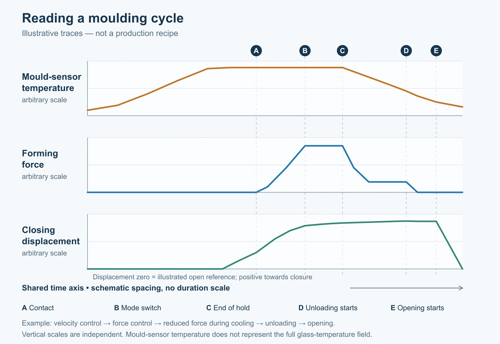
A moulding cycle consists of connected stages. The sequence and transition logic depend on the machine configuration, glass, preform and tooling.
The following examples illustrate how stage completion can be defined. Actual criteria must be established for the relevant process.
| Process stage | Main control objective | Example of a stage-completion criterion |
|---|---|---|
| Preparation and loading | Confirm the starting condition | Identity, cleanliness and seating checks pass |
| Atmosphere preparation | Establish the chamber environment | Purge or evacuation sequence and atmosphere criteria pass |
| Heating and soaking | Establish repeatable thermal conditions | Designated sensors meet limits and the required soak completes |
| Approach and initial contact | Establish controlled contact | A validated contact signal triggers forming mode |
| Forming | Develop geometry and optical contact | The governing criterion is reached within monitored limits |
| Holding | Complete the intended deformation or relaxation | Hold duration and force or position criteria pass |
| Cooling and unloading | Retain shape as glass stiffens | Temperature and load-release criteria are reached |
| Release and inspection | Remove and evaluate the part | Release completes; inspection and disposition follow |
The recipe should identify what happens if a transition criterion is not reached within the permitted time. An incomplete stage needs a defined response and part disposition.
Machine architecture also matters. Some processes bring the glass and mould towards similar temperatures before pressing. Others intentionally use different glass and mould temperatures, making transfer delay and contact heat transfer particularly important.
Matching displayed settings between different machines does not establish equivalent forming conditions.
Preform, Tooling and Loading Controls
Before production, the setup should identify the glass grade and lot, preform specification, mould inserts, coating condition, assembly arrangement and recipe revision. The machine and measurement systems must also be suitable for the planned run.
Preform Condition and Position
Confirm accepted preform mass and dimensions, cleanliness, dryness, seating and any orientation requirement. Define approved handling tools and contact locations, with checks for missing or incorrectly positioned preforms. Particles and residues can disturb optical contact and damage the glass or tooling.
For material screening and preform specification, see Optical Glass and Preform Selection for Precision Glass Moulding.
Tooling Condition and History
Cleaning, coating wear, surface damage or a replacement insert can change friction, heat transfer and release behaviour. A previously successful recipe may require verification after these changes.
Tooling records should connect insert identity with coating history, maintenance, cleaning, production exposure and inspection findings. Cycle count is useful, but it should be considered alongside observed condition and product quality.
Material selection, coating failure and maintenance are discussed in the companion guide Mould Design, Tooling and Release-Coating Control. Here, use that history to identify changes that require setup checks or renewed process verification.
Control the Chamber Atmosphere
Gas composition, residual oxygen, moisture, contamination and chamber pressure can affect interface reactions and tooling behaviour. Their significance depends on the glass, mould substrate, release coating and thermal exposure.
Gas supply purity alone does not establish the conditions around the hot mould. Leaks, trapped air, surface moisture and the purge sequence can influence the actual chamber environment.
Specify gas identity and supply requirements, purge or evacuation sequence, operating pressure, gas flow, relevant oxygen or moisture criteria, and the measurement locations. Define the response when an atmosphere requirement is not met.
Chamber pressure must be identified as absolute or gauge pressure. Where gas-flow values depend on reference temperature and pressure, those conditions should also be clear.
Monitoring requirements should follow the risks of the actual process. Some systems need direct oxygen or moisture monitoring; others use a validated atmosphere-control method supported by appropriate checks. The documentation should distinguish measured conditions from those established indirectly.
A vacuum reading does not independently prove an acceptable oxygen or moisture level. Evacuation should also not be assumed to remove bubbles already enclosed within a preform.
Heating, Soaking and Glass Temperature Control
Temperature control establishes the material condition in which pressing takes place. It must address both the temperature level and its distribution through the glass and tooling.
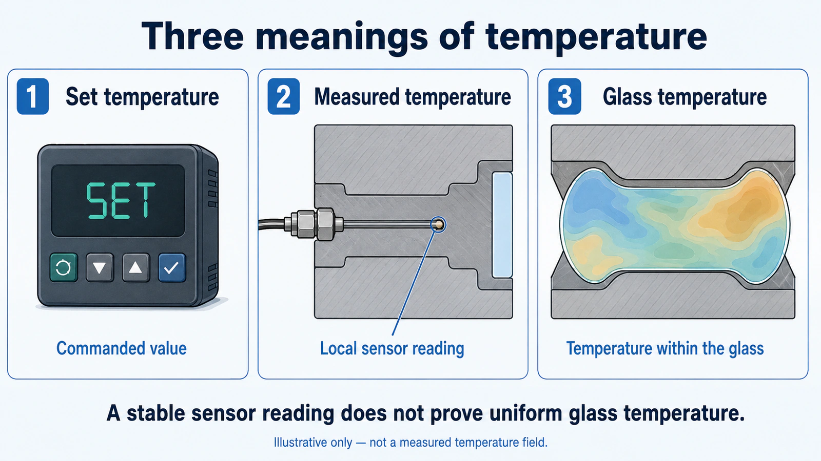
Set Temperature, Measured Temperature and Glass Temperature
These three quantities have different meanings:
- Set temperature is the value commanded by the controller.
- Measured temperature is the reading at an identified sensor location.
- Glass temperature is the temperature distribution within the preform.
A mould thermocouple measures conditions near its installation point. It does not directly measure every glass–mould contact location or the centre of the preform. Sensor response, installation and thermal lag influence how the reading relates to the glass.
Nonuniform temperature fields can cause different regions of the glass to deform differently. Experimental research has demonstrated effects on both deformation and optical quality. Li et al. (2020): Temperature effect on deformation and optical quality
During qualification, temperature mapping, instrumented trials or a validated model can help establish the relationship between machine measurements and the forming condition. Production documents should identify any inferred temperatures.
Glass Viscosity and Forming Response
Viscosity describes resistance to flow. Within the relevant forming range, increasing temperature generally lowers glass viscosity, while cooling increases it. Near the transformation range, the material response also depends on time and structural relaxation. SCHOTT TIE-31: Mechanical and thermal properties of optical glass
At a given forming speed, glass in a more resistant thermal condition generally requires greater force. Under a maintained force, glass capable of flowing can continue to deform. Consequently, a temperature change can affect the force trace, forming duration and final geometry even when the nominal movement programme remains unchanged.
Tg identifies transformation behaviour under specified measurement conditions. It does not provide a complete viscosity–temperature relationship or a production recipe.
Different glass grades can have different forming responses. Changing the glass therefore requires a review of temperature, forming rate and holding conditions rather than direct reuse of the previous settings.
Heating and Soak Timing
The heating programme should define ramp rates, permissible overshoot, relevant temperature differences and the criteria used to start the soak timer.
For example, soaking may begin only after designated mould sensors enter their specified ranges. Qualification must establish whether the subsequent soak produces a suitable glass condition; stable sensor readings alone do not prove uniform preform temperature.
Insufficient heating can leave the glass too resistant to deformation. Excessive temperature or unnecessary hot exposure may increase sticking, surface reaction, crystallisation or tooling deterioration, depending on the material system.
Forming Force, Control Modes and Initial Contact
Force and movement must be described clearly because their relationship changes as the glass deforms.
Forming Force and Pressure
“Pressure” may refer to actuator pressure, chamber pressure, calculated nominal pressure or local glass–mould contact pressure.
These quantities should remain separate in process documents.
Forming force is an applied load, normally expressed in newtons or kilonewtons. If nominal pressure is reported, its reference area must be stated:
Nominal pressure = forming force ÷ declared reference area.
This calculation does not establish uniform pressure across the optical surface. Contact area changes during forming, and local pressure depends on geometry, temperature, friction and tooling behaviour.
Hydraulic or pneumatic actuator pressure also requires an appropriate relationship to delivered force before it can be used to describe the forming load.
Force, Position and Velocity Control
Under force control, the machine adjusts movement to maintain the specified force. Displacement may continue while the glass remains capable of flowing.
Under position control, the machine follows or holds a specified position. Force may change as the glass relaxes and the tooling assembly responds.
Under velocity control, the machine follows a specified movement rate, subject to the relevant force and position limits.
A cycle may use different modes at different stages. The recipe should identify the governing variable, the monitored limits and the transition between modes. Force and position cannot generally be prescribed as independent, arbitrary targets throughout the same deformation stage.
A machine-position value also requires a defined reference before it can be related to mould separation.
Initial Contact and Load Application
The approach stage establishes the starting condition for forming.
The setup should define approach speed, any reduced-speed contact region, contact-detection method, initial preload where applicable and the transition into the main forming stage.
Contact criteria need verification under the intended thermal conditions. Tooling expansion and preform geometry influence when contact occurs.
An unexpected contact position should prompt checks of preform seating and geometry, tooling stack height and the position reference. An unusually high force after contact should also prompt a review of thermal condition, forming speed and interface behaviour. Investigate the cause before increasing a forming limit.
Coordinate the Forming Variables
Evaluate adjustments against a specific requirement. A temperature increase may ease deformation while changing interface behaviour; a speed increase may raise force; additional holding changes both deformation and thermal exposure. Compare contact position, force rise, displacement and stage duration with the qualified sequence, then confirm the effect through finished-part measurements.
A higher force cannot replace missing glass volume. Extra holding does not reliably correct contamination or misalignment. The selected combination must balance optical and dimensional quality, release behaviour, cycle time and tooling condition.
Control Mould Closure, Material Flow and Thickness
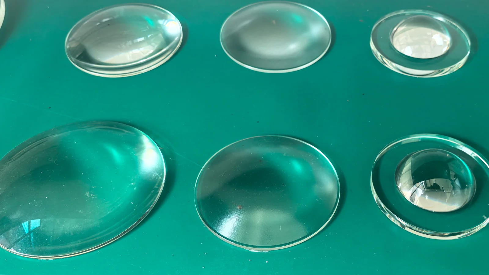
Final machine position is not automatically equal to finished centre thickness.
The relationship can be influenced by the position reference, machine compliance, thermal expansion of the tooling stack, elastic mould deflection and subsequent glass contraction.
Where mechanical stops are used, their condition and thermal behaviour also form part of the setup.
Qualification should establish how recorded position or measured mould separation relates to finished dimensions at the specified inspection condition. This relationship needs to include the relevant load, temperature and tooling arrangement.
Preform volume must also match the cavity and edge design.
Depending on the tooling configuration, excess material may increase peripheral glass, prevent the intended closure or produce an abnormal load rise. Insufficient material may leave incomplete geometry or inadequate surface contact.
A thickness deviation should therefore be investigated alongside preform measurements, forming traces and tooling condition.
Changing the closing position may be an appropriate adjustment within an established process, but it should follow an understanding of the deviation. Otherwise, a material or thermal problem can remain hidden.
Holding, Cooling Transition and Controlled Release
Define whether holding is intended to complete deformation, maintain contact or permit relaxation, and use the appropriate control mode. Relaxation during the hold does not establish the final residual-stress result: subsequent cooling and restraint continue to affect shape and stress. Liu and Zhang (2015): Thermoforming mechanism of precision glass moulding
The recipe should specify:
- What ends the forming or holding stage.
- Which signal governs the transition.
- How force or position changes during cooling.
- Maximum permitted holding times.
- Conditions for unloading and mould opening.
As the glass stiffens and the tooling assembly contracts, the restraint needs to remain compatible with shape retention and release.
Full forming force throughout cooling is not a universal requirement. Likewise, reaching a temperature below Tg does not independently establish that demoulding will be acceptable.
Release qualification should evaluate the relevant glass temperature, tool separation sequence, adhesion behaviour and handling condition. Finished parts should be checked for release marks, edge damage and any associated geometry change.
This section addresses the transition from forming to release. Detailed cooling-profile development must also evaluate refractive-index effects, residual stress and any separate annealing requirement against the finished optical specification.
Process Monitoring and Measurement Reliability
Record the temperature, force, displacement, movement rate, stage events and atmosphere signals required by the control plan. Link each cycle to its recipe revision, material lot, tooling, alarms and interventions.
Each channel needs a clear definition: what is measured, where it is measured, its units and whether the value is commanded, measured or calculated.
Record Enough Detail to Resolve Important Events
Record at a rate that resolves contact, rapid force changes and mode transitions, with channels aligned in time. A maximum force value alone cannot show the loading sequence.
A comparison with qualified production traces can reveal changes such as earlier contact, a longer forming stage or altered displacement during holding. These differences provide investigation evidence; they do not identify a root cause by themselves.
A familiar trace also does not replace product inspection.
Verify the Measurement System
Display resolution does not establish measurement accuracy.
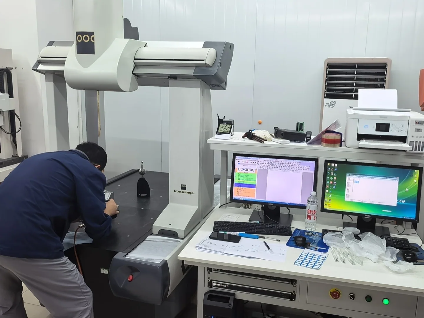
The measurement plan should consider calibration, sensor installation, zero or reference conditions, repeatability, response time and drift. If a reading is used to infer another quantity, such as mould separation or glass temperature, that relationship should be verified.
Sensor replacement or relocation can change the meaning of an established setting. Its effect should be reviewed before normal production resumes.
Finished-part measurements also require consistent thermal stabilisation, datums, evaluation apertures and analysis methods.
Establish the Approved Process Window
An approved process window describes the combinations of conditions demonstrated to produce acceptable components.
It should distinguish production targets, validated variation, response thresholds and product acceptance criteria.
| Control concept | What it defines |
|---|---|
| Target settings | The normal operating conditions selected for production |
| Validated process range | The combinations and variation demonstrated to meet the relevant requirements |
| Alarm and stop conditions | The deviations that require review, intervention or production interruption |
| Product acceptance limits | The optical, dimensional and other requirements used to accept or reject components |
Equipment protection limits may sit outside a narrower process range. The fact that a machine can continue running does not establish that the product remains within its qualified manufacturing conditions.
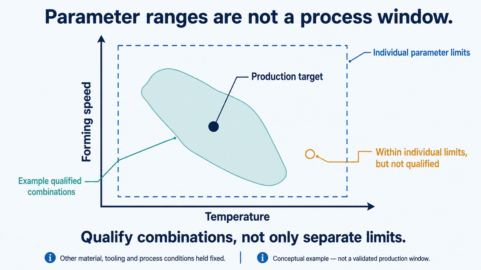
Parameter interactions are central to window development. Temperature, force and speed may each have an acceptable range, while some combinations within those separate ranges remain untested or unsuitable.
The approved recipe should identify dependencies between parameters, rather than presenting every limit as independently adjustable. Document permitted combinations or conditional limits clearly enough for operators to apply them consistently.
Designed experiments can help evaluate individual effects and interactions. NIST/SEMATECH e-Handbook: Two-level full factorial designs
Development trials should evaluate the relevant quality responses, including surface form, thickness, optical performance, cosmetic condition and release behaviour. Tooling exposure and cycle time also matter.
Repeating selected conditions across suitable runs helps distinguish a parameter effect from changes in material, machine temperature or tooling condition.
The production target should provide margin against the variation demonstrated during qualification. A successful isolated trial provides less evidence than repeatable results across the conditions expected in production.
Validate Startups, Restarts and Multi-Cavity Production
Validate how the machine and tooling reach their operating condition after a cold start, prolonged idle period, interruption or maintenance. Define the records and product checks needed to release production. Any startup-part rejection quantity should follow validation and inspection evidence; there is no universal number.
Parts from incomplete cycles require a defined disposition. Reheating or remoulding should not be assumed acceptable because additional thermal exposure may change the material or its interaction with the tooling.
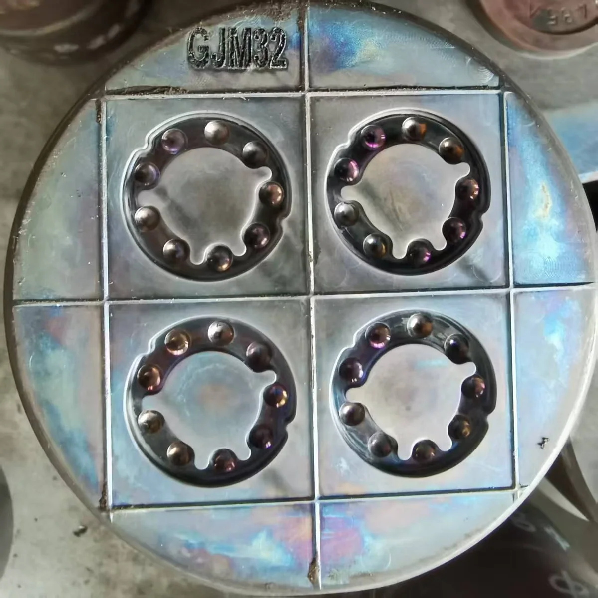
For multi-cavity production, total machine force does not prove equal loading in every cavity. Local differences in temperature, alignment, tooling condition and preform position can produce different results.
Qualification and inspection should retain cavity identity where needed to understand variation. Averaging all cavities can hide a recurring problem in one location.
Transfer systems should also control the timing between heating, movement and pressing. Changes in station timing or loading configuration need review when they alter the thermal or mechanical conditions.
In-Process Inspection, Deviation Response and Change Control
Combine evidence that the cycle followed its approved conditions with inspection demonstrating component conformity.
Inspection and Statistical Evaluation
An inspection plan may include setup approval, first-off checks, periodic sampling, checks after relevant interventions and final lot review.
Sampling should reflect the critical characteristics, production history, observed variation and consequences of an undetected defect. Dimensions, surface appearance, form, centration and functional optical properties require appropriate methods.
Statistical process control helps detect changes in process behaviour. Statistical control limits describe that behaviour; product specification limits define acceptance.
A stable process can still produce components outside specification. Capability assessment compares a stable process with the relevant limits and requires suitable data and statistical assumptions. NIST/SEMATECH e-Handbook: What is process capability?
Measurement reliability, sample selection, data dependence and distribution shape affect interpretation. A centre-thickness capability result cannot establish capability for wavefront, surface defects or every other optical requirement.
Responding to Deviations
The reaction plan should identify who reviews a deviation, when production pauses, how potentially affected components are identified and what evidence is needed before production resumes.
Parts produced outside the approved process window should follow the defined deviation-review route, even when sampled dimensions remain within specification. Hold the affected population for review and document the evidence supporting acceptance, additional inspection, rework or rejection; passing one sampled characteristic does not close the deviation.
The affected population can be assessed using timestamps, cycle records, cavity identity, the last acceptable inspection and subsequent checks.
Investigations should connect the observed defect with process traces, material information, tooling history and measurement reliability. Adjustments and failed cycles should remain traceable.
Controlling Changes
Changes requiring review may include:
- Glass grade or preform specification.
- Mould geometry, coating system or assembly arrangement.
- Machine hardware or control logic.
- Sensor installation or position reference.
- Operating conditions outside the established range.
- Cooling, unloading or release sequence.
The extent of verification should match the potential effect on the product. Equivalent-looking settings do not prove equivalent conditions after a change.
What Buyers Should Review with a Moulding Supplier
Buyers can assess process maturity through the connection between requirements, controls and evidence.
Focus the review on four areas:
- Process validation: Which product characteristics govern development, and what evidence qualifies the glass–preform–tooling combination?
- Monitoring and inspection: Which actual signals are recorded, and which component measurements support production release?
- Startup and maintenance: How are restarts, cavity differences and tooling deterioration evaluated?
- Traceability and changes: How are affected parts identified, deviations resolved and relevant changes requalified?
A successful prototype demonstrates feasibility under the conditions of that trial. Production qualification should also address repeatability, routine variation and the intended tooling-maintenance cycle.
The supplier does not need to disclose every proprietary recipe value to provide useful evidence. The agreed documentation can focus on critical requirements, validation results, traceability, inspection and change-control arrangements.
Frequently asked questions
What Is the Correct Temperature for Precision Glass Moulding?
It depends on the glass’s forming behaviour, component geometry, tooling interface and movement programme. Tg and material data guide development, but the operating condition must be established for the actual process.
Is Forming Force the Same as Moulding Pressure?
Force is an applied load. Nominal pressure requires a declared reference area, while local contact pressure changes with the glass–mould contact conditions. Chamber and actuator pressures are separate quantities.
Can Higher Force Correct Incomplete Surface Replication?
It may help in some circumstances, but the cause needs investigation. Insufficient heating, unsuitable preform geometry, contamination or trapped gas may require a different correction.
Does a Longer Hold Always Improve Quality?
Additional time may allow further deformation or relaxation. It also changes thermal exposure and cycle time. The result must be evaluated against optical quality, release behaviour and tooling condition.
Can a Recipe Be Transferred to Another Machine?
It can provide a development starting point. Differences in heating, sensor location, mechanical compliance, movement control and timing require verification before production approval.
Does Every Moulded Component Require Separate Annealing?
No. The required treatment depends on the glass, thermal history and finished-component requirements. Some processes achieve the required condition through controlled cooling within the moulding cycle; others require an additional treatment.
Contact Us
Your feedback fuels our growth, and your questions drive our solutions.
We value your feedback, inquiries, and suggestions. Please feel free to get in touch with us
General inquiries
Please contact us via sales@bo-glass.com, and we will reply to you as soon as possible.
Interested to work with us
Drop your resume at info@bo-glass.com
and we will get back to you shortly.
We uses the contact information you provide to us to contact you about our relevent content, products, and services.