
Manufacturing and Design Guidelines
Precision glass moulding
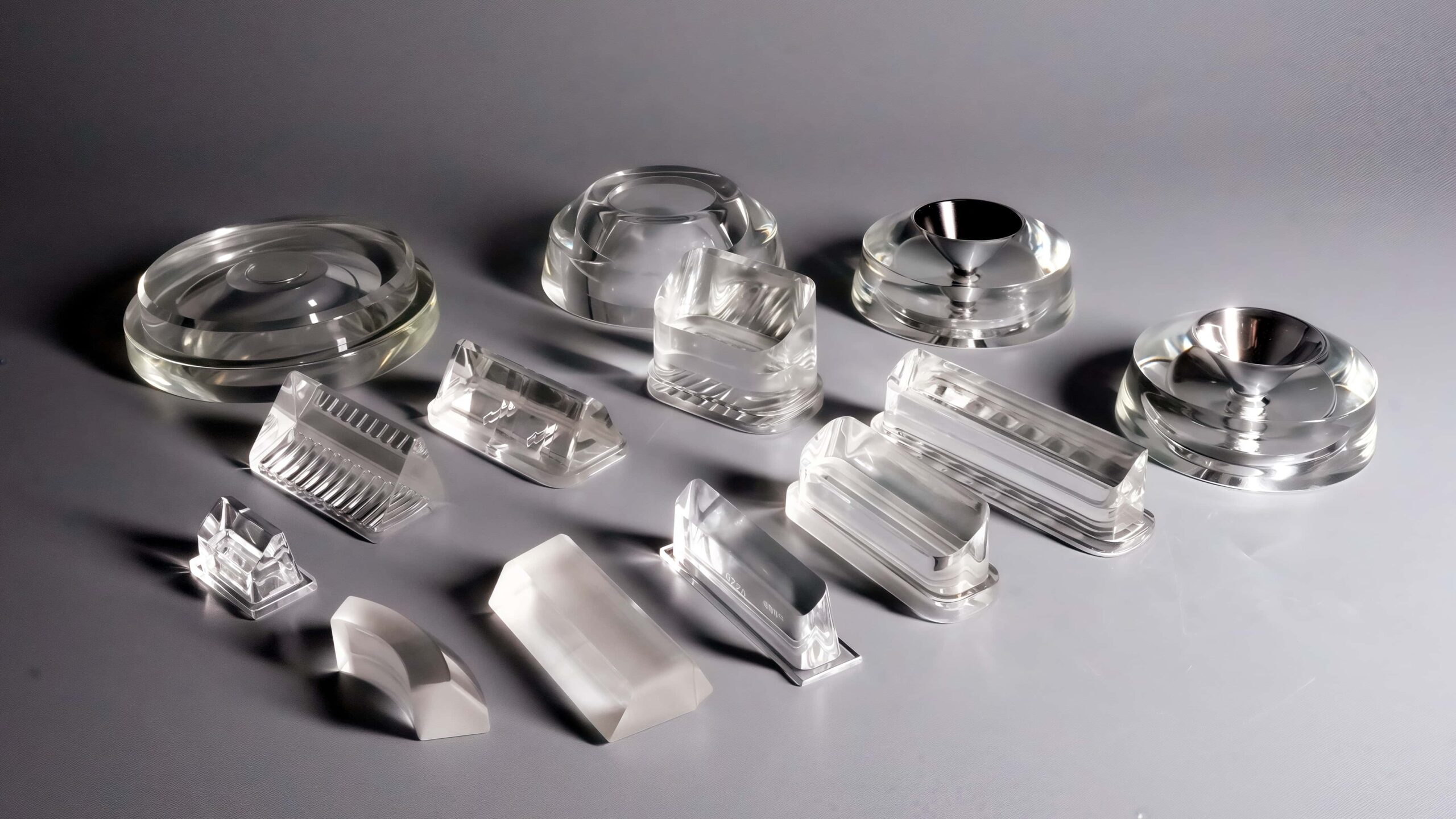
Choose a manufacturing route, find the relevant technical guide and agree what evidence is needed before moving from a drawing to repeat production.
Explore the Six Technical Chapters
Choose a topic below to open its detailed guide. For a new design, start with Chapters 01 and 02; for a quality issue, start with Chapter 06.
Precision Glass Moulding Design Guide: Materials, Geometry and Tolerances
Define optical surfaces, clear aperture, thickness, datums and tolerances for a manufacturing review.
Read the design guide → CHAPTER 02 · MATERIALSOptical Glass and Preform Selection for Precision Glass Moulding
Assess glass suitability and specify preform mass, geometry, surface condition and traceability.
Read the material guide → CHAPTER 03 · TOOLINGMould Design, Tooling and Release-Coating Control
Review mould architecture, alignment, release coatings, maintenance and glass–mould interface problems.
Read the tooling guide → CHAPTER 04 · PROCESSPrecision Glass Moulding Process Control
Connect heating, contact, force, displacement and atmosphere with consistent forming conditions.
Read the process guide → CHAPTER 05 · VALIDATIONThermal Cycle, Cooling and Optical Performance Validation
Define cooling, stress and optical checks for sample approval and thermal-exposure validation.
Read the validation guide → CHAPTER 06 · TROUBLESHOOTINGPrecision Glass Moulding Defects and Troubleshooting
Compare defect patterns, identify possible causes and verify corrections using production evidence.
Read the troubleshooting guide →Choose the Manufacturing Route from the Finished Requirement
Precision glass moulding brings optical design, suitable glass preforms, precision tooling and thermal processing together to replicate optical surfaces. Success depends on the finished component meeting its dimensional, optical and application requirements, not simply on reproducing its outline.
Glass rod describes a starting material form, not a guarantee of precision-moulded optical quality. The forming process and required delivery condition distinguish precision optical moulding from conventional pressing and pressed blanks that need later grinding and polishing.
At a glance: Define the function and delivery state first. Select the material and manufacturing route together, agree measurable acceptance criteria, and separate sample approval from evidence of repeatable production. The six technical chapters support each decision without prescribing a universal process recipe.
Start with the optical task: imaging, beam shaping, transmission, light distribution or an interface within an assembly. Then establish geometry, material requirements, operating conditions and production demand.
The routes below are comparison options, not mutually exclusive equipment categories. Conventional pressing may be one stage in a route that finishes with grinding and polishing. Compare the complete sequence and its promised delivery state.
| Route | When to consider it | What must be confirmed |
|---|---|---|
| Precision glass moulding | Optical surfaces suitable for replication with compatible preforms and precision tooling | Glass suitability, geometry, release, thermal effects and final optical acceptance |
| Conventional glass pressing | Shapes and surface requirements suited to the selected pressing process | Surface condition, dimensions, material compatibility and any subsequent finishing |
| Pressed blank followed by grinding and polishing | Pressing supplies an initial shape rather than the finished optical surface | Finishing allowance, glass quality, reference features and responsibility for final acceptance |
| Material-removal route | Material, geometry, quantity or tolerances favour machining, grinding or polishing | Surface access, processing sequence, material availability and inspection feasibility |
SCHOTT describes polished or fire-polished preforms for precision moulding, including suitable rod forms, and distinguishes them from reheat-pressed blanks requiring additional surface finishing. A component quoted as a blank should not be compared with a finished optic on unit price alone. SCHOTT TIE-40: Optical glass for precision molding
Consider glass and preform procurement, tooling and its maintenance, development trials, cycle time, yield, secondary operations, inspection and packaging. Quantity affects economics, but no single volume threshold makes moulding the preferred route for every design. The useful comparison is the cost and risk of meeting the complete specification.
Understand the Basic Moulding Sequence
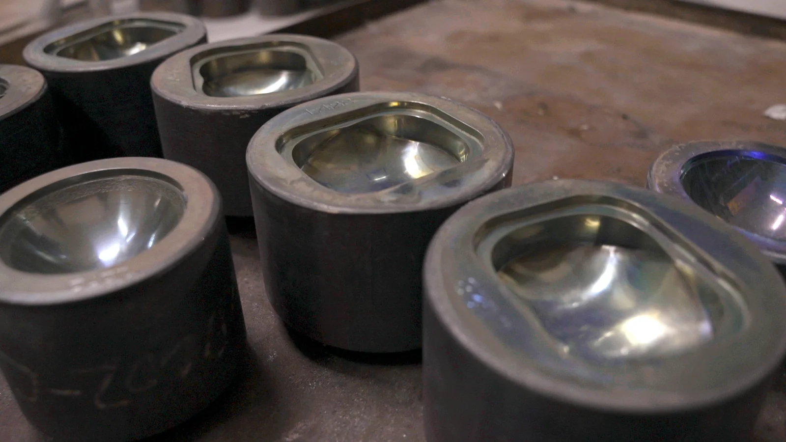
The process coordinates glass condition, tool geometry, the contacting interface and the thermal cycle. Equipment arrangements differ, but the main purposes of the stages remain recognisable.
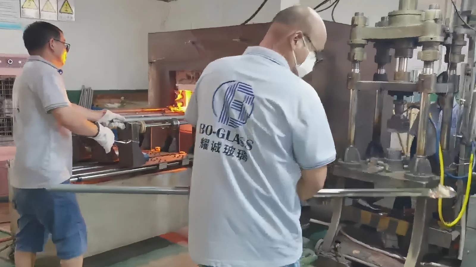
- Prepare the preform. Verify material, specified mass and geometry, surface condition and cleanliness.
- Prepare and load the tooling. Check condition, alignment, cavity identity and preform position.
- Establish the atmosphere. Use the gas or evacuation sequence qualified for the material, tool and equipment.
- Heat and soak. Establish the thermal state required for deformation, allowing for the relationship between sensor location and the glass.
- Form the component. Coordinate force, displacement, speed and time as contact develops.
- Cool and release. Control thermal history, restraint changes and separation to preserve geometry and surface condition.
- Inspect, finish and verify the delivery condition. Perform intermediate checks as needed, complete specified finishing, coating or assembly, and verify applicable requirements at the agreed delivery state.
Glass viscosity changes with temperature, so temperature, force and time cannot be selected independently. Tg is useful material information, not the moulding setpoint. A machine reading does not establish temperature everywhere inside the glass, and the same applied force can act over different contact areas during forming.
Cooling is part of the production route, not simply a waiting period. Some projects meet their requirements through the integrated cycle; others need a separately qualified thermal treatment. The decision must consider form and optical properties as well as stress.
Tool release coatings and optical coatings on the delivered glass also need separate specifications: the former support the moulding interface, while the latter serve optical requirements such as transmission or reflection.
Confirm Feasibility and Comparable Acceptance Criteria
Diameter alone does not describe difficulty. Review surface slope and sag, thickness distribution, edges, clear aperture and the relationship between optical and mechanical features. The tool surfaces must be manufacturable and measurable, the glass must reach the required shape, and the component must be releasable without unacceptable damage.
A material chosen for refractive index and dispersion must also suit the tooling and thermal process. Similar catalogue optical constants do not establish equivalent mouldability or the same optical state after processing. Any substitution needs both an optical and a manufacturing review.
Define which characteristics control function and how they will be evaluated. Four common comparison errors are particularly important:
| Requirement | Distinction that matters |
|---|---|
| Surface form | Absolute geometry differs from residual error after permitted fitting or removed terms; specify aperture and metric |
| Transmission | Internal glass transmittance differs from transmission through the finished component; align wavelength, path length and coating state |
| Stress birefringence | Optical retardation and mechanical stress are different quantities; state units, light path and interpretation |
| Focal or wavefront performance | Results depend on the optical configuration, reference condition and focus convention, not only the part |
Internal transmittance excludes surface-reflection losses, whereas a finished component includes the effects of its surfaces and coating. A quoted transmission value therefore needs an identified quantity and test condition. SCHOTT TIE-35: Transmittance of optical glass
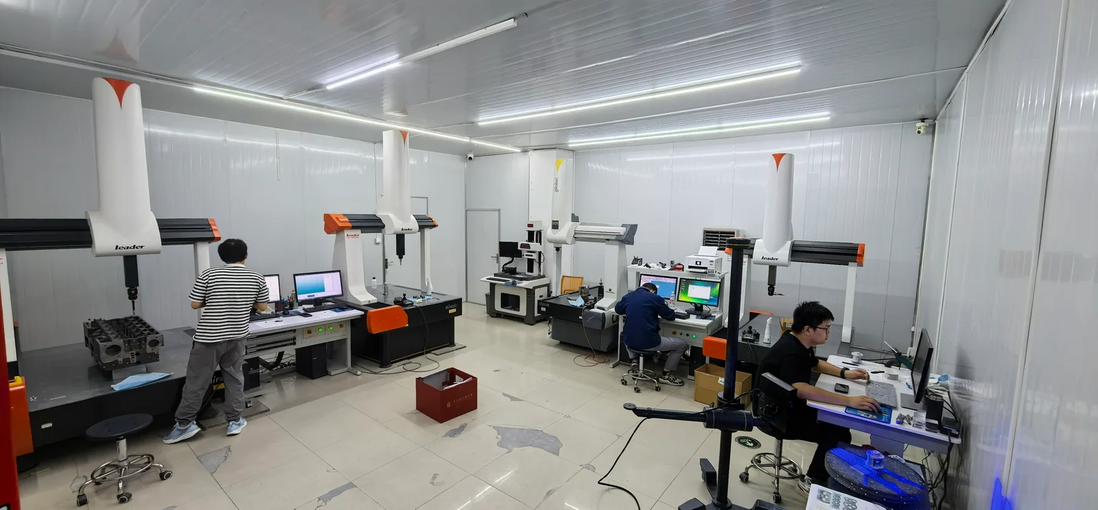
Agree the inspection method, calibration basis, relevant uncertainty and treatment of borderline results. Instrument resolution alone does not establish suitability for a tolerance. A satisfactory surface-form result likewise does not establish every aspect of transmitted performance.
Record which requirements are confirmed, which need development trials and which fall outside the proposed scope. Detailed measurement definitions belong in the component specification and the validation plan, supported by Chapter 05.
Match Validation to the Application
The examples below identify requirements to discuss, not qualified manufacturing capability for every listed application. Select only the tests relevant to the agreed function and use conditions.
Imaging and sensing. Coordinate surface form, centration, thickness, material properties and assembly position. For wavefront or MTF acceptance, define wavelength, aperture, field and focus conditions so that the optical test matches the intended configuration.
LED illumination and beam shaping. Treat the source as part of the requirement. Emitter size, position, angular output and its location relative to the glass affect beam angle, distribution and uniformity. Compare results using an agreed source and mounting arrangement.
Laser and polarisation-sensitive systems. Discuss wavefront, transmission, surface quality, cleanliness and birefringence at the operating wavelength. If laser-damage performance is required, agree an appropriate test basis for the actual supplied component and coating state rather than inferring it from material identity.
Arrays and freeform optics. Define coordinates, feature orientation and datums. Local surface quality does not establish performance across an entire array: feature position, pitch and variation over the active area may also require verification.
Temperature exposure. State the operating range, exposure pattern and mounting constraints. Distinguish performance while hot or cold from performance after recovery to a reference temperature; retained performance after exposure does not establish performance throughout the operating range.
Move from Design Review to Approved Production
Development should produce a documented decision at each stage, rather than an increasingly detailed list of machine settings.
Establish the Design and Acceptance Basis
Resolve the optical prescription, material constraints, critical dimensions, delivery state and measurement methods. Record assumptions and open decisions so that acceptance of a sample is not mistaken for agreement to an undefined requirement.
The outcome is a shared specification and a feasible development scope, including any requirements still dependent on trials.
Validate the Combined Process
Evaluate the preform, tooling, heating, forming, cooling and release together. Thermal history can influence both profile deviation and residual stress, so improving one result must not compromise another requirement. Liu and Zhang (2015): Thermoforming mechanism of precision glass moulding
Keep material, tool and process identity linked to trial results. Include checks after secondary operations when they could affect critical properties; an intermediate approval does not replace verification of the final delivery condition.
Demonstrate Relevant Repeatability
One acceptable sample is evidence for that sample and its conditions, not a general production guarantee. Choose representative runs, cavities, material variation, startup states or stages of tool use according to the project risk.
Statistical stability and specification compliance answer different questions. Process-capability assessment requires suitable data and assumptions; a result for one dimension cannot establish capability for every optical characteristic. NIST: What is process capability?
The outcome should be an agreed sample-approval basis and an inspection plan appropriate for routine supply, including the response to nonconforming results.
Control Production Conditions and Changes
Distinguish target settings, demonstrated process ranges, alarm/stop conditions and product acceptance limits. Parameters can each lie within individual limits while their combined condition remains unvalidated; record relevant interactions and restrictions.
Keep the material, preform, tool/coating condition, equipment configuration and process revisions traceable. Assess changes for their effect on the approved result and agree when further trials, inspection or customer approval are needed.
Detailed recipes may remain supplier-controlled. Agree which validation results, traceability records and change notifications form part of the customer approval package; control of the process does not automatically imply delivery of proprietary settings.
Compare Sourcing Scope and Responsibilities
A technically useful enquiry defines the finished requirement without requiring the buyer to design the mould or supply a forming recipe. Organise the initial information into four groups:
- Drawing and function: revision, surface definitions, datums and the intended optical task; identify fixed requirements and open design choices.
- Material and use conditions: fixed glass grade or selection criteria, wavelength range, source, mounting and environmental exposure.
- Acceptance and delivery: critical dimensional/optical limits, surface and edge condition, finishing or coating state, reports and traceability.
- Quantity and timing: development samples, order size, expected repeat demand and required milestones.
Where information is incomplete, a preliminary quotation should identify assumptions, exclusions and what must be resolved before tooling or production commitment. Existing samples and inspection reports can clarify a replacement part or established quality issue.
Compare quotations on the same delivery state and included work. Separate tooling and development charges from recurring part cost, and identify whether secondary finishing, optical coating, inspection documentation and packaging are included. A lower moulded-part price may exclude operations needed for the accepted component.
Agree who is responsible for final optical acceptance when more than one supplier performs the route. Where relevant, document tooling ownership, storage, maintenance, replacement and the consequences of a design or material change. If a production step or inspection is subcontracted, clarify the applicable controls and reporting responsibility.
The approval package should align engineering and purchasing: what will be supplied, which evidence supports acceptance, which assumptions remain open and how changes or nonconformities will be handled. That shared scope is the basis for moving from development samples to repeat production.
Contact Us
Your feedback fuels our growth, and your questions drive our solutions.
We value your feedback, inquiries, and suggestions. Please feel free to get in touch with us
General inquiries
Please contact us via sales@bo-glass.com, and we will reply to you as soon as possible.
Interested to work with us
Drop your resume at info@bo-glass.com
and we will get back to you shortly.
We uses the contact information you provide to us to contact you about our relevent content, products, and services.