
← Back to the glass rod pressing technology guide
Precision Glass Moulding Design Guide: Materials, Geometry and Tolerances
Precision glass moulding (PGM), also known as precision glass molding, is a near-net-shape process for producing repeatable glass optics, particularly spherical, aspherical and freeform components. A precision preform is heated into a controlled viscosity range and formed between accurately machined mould inserts.
The process can eliminate grinding and polishing on the functional optical surfaces, but successful production depends on more than the nominal lens shape. The optical prescription, glass and preform, component geometry, mould construction, thermal cycle and inspection method must be developed as one connected system.
This guide explains when precision glass moulding is appropriate and how to prepare a moulding-ready optical design and drawing package.
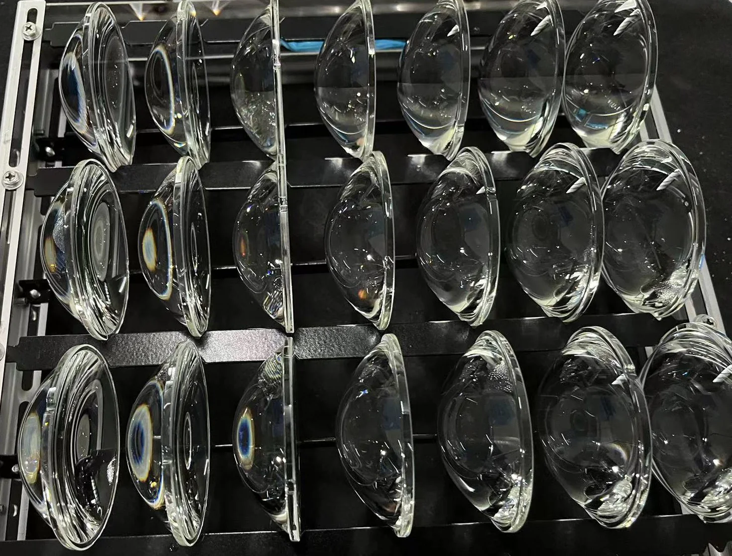
At a glance: Precision glass moulding is usually a strong candidate when a complex glass surface must be replicated repeatedly, the glass has a suitable moulding window, the geometry can be filled and released, and the required tolerances can be verified with an agreed measurement method.
Use four initial questions to screen a component: Does the expected volume justify dedicated tooling? Is the selected glass mouldable? Can the geometry fill and release? Can the critical requirements be measured repeatably?
How precision glass moulding works
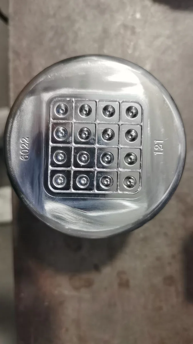
Precision glass moulding forms a heated glass preform between two accurately aligned mould inserts. The mould surfaces contain the negative geometry of the finished optical component, including its spherical, aspherical or freeform features.
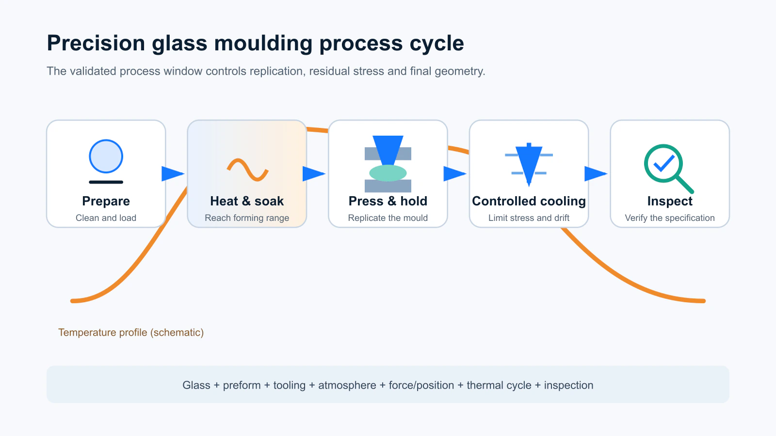
A typical cycle includes:
- Clean, inspect and load the preform.
- Prepare the controlled process atmosphere.
- Heat and soak the glass in the required viscosity range.
- Press and hold using a defined force or position strategy.
- Cool under control to limit distortion and residual stress.
- Demould, clean and inspect the component.
Temperature, force, time and atmosphere depend on the glass, preform, component geometry, mould system and equipment. The process is near-net-shape because it produces the functional optical surfaces directly, although edge grinding, centring, coating or cleaning may still be required.
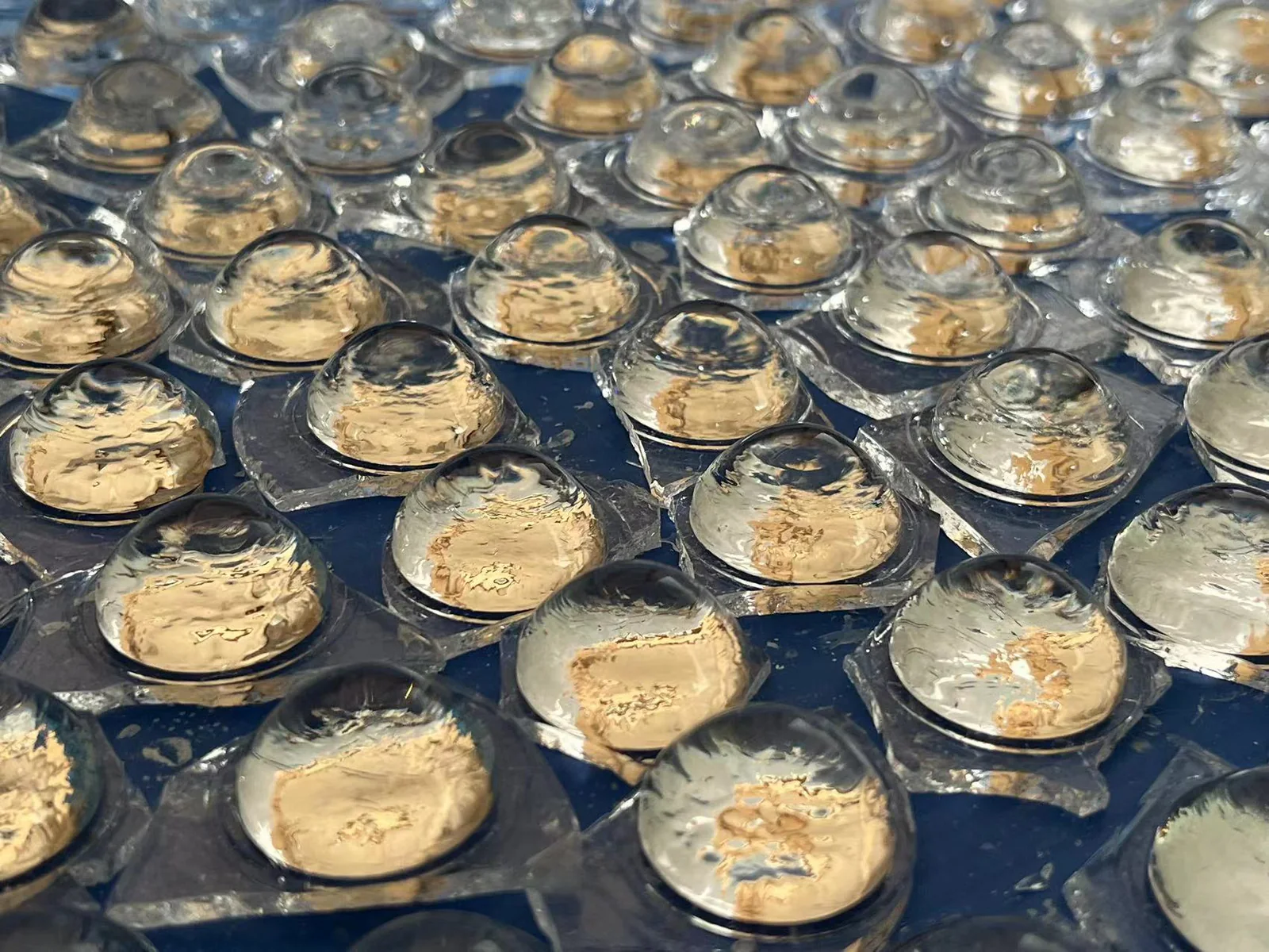
Precision glass moulding is not the same as conventional hot pressing. Conventional pressing is widely used for lighting lenses, covers, reflectors and larger non-imaging products, but it normally operates with different tooling, glass conditions, tolerances and surface-quality expectations.
Is precision glass moulding right for your component?
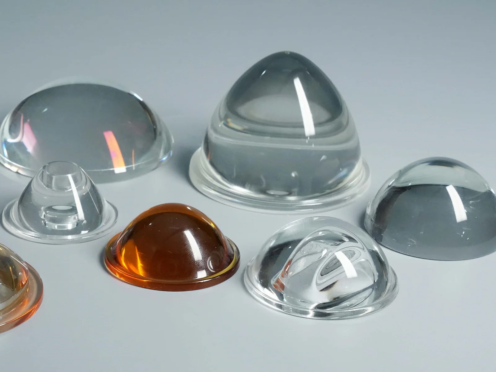
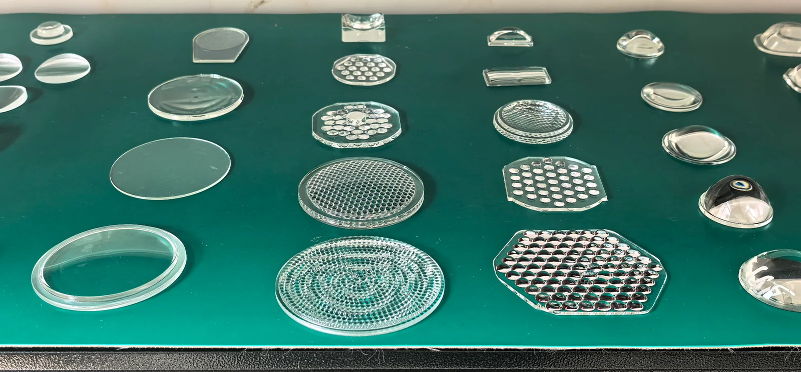
PGM is most competitive when a complex surface must be repeated in production and transferred directly from a durable precision mould. Applications include compact imaging lenses, aspheres, sensor optics, LED collimators and laser optics.
It may be less attractive for one-off prototypes, unusually large optics, glass grades with unsuitable forming behaviour, parts requiring extensive material removal after moulding, or geometries that cannot be released without damaging the optical surface.
Tight tolerances do not automatically make PGM the best route; they must be evaluated against mould accuracy, thermal deformation, glass shrinkage, repeatability and measurement capability.
| Manufacturing method | Best suited for | Main limitation |
|---|---|---|
| Precision glass moulding | Repeat-production aspheres, freeforms and compact precision optics | Dedicated tooling and qualification are required |
| Grinding and polishing | Prototypes, larger optics and a broad range of glass grades | Repeated complex surfaces can require more processing time and cost |
| Conventional glass pressing | Lighting lenses, patterned covers and non-imaging components | Standard capability should not be assumed to equal precision optical moulding |
| Plastic injection moulding | Lightweight components and very high production volumes | Thermal stability, hardness, spectral performance and long-term stability may be limiting |
Select the manufacturing route from the finished optical, environmental and commercial requirements rather than from surface shape alone.
Select the glass and preform for moulding
Optical performance is only one part of glass selection. A grade with the desired refractive index and dispersion may still be difficult to mould because of its forming temperature, crystallisation behaviour or chemical interaction with the mould system.
Before freezing the design, review:
- Glass transition temperature, viscosity-temperature data and supported forming range
- Devitrification and chemical interaction with the mould and release coating
- Thermal expansion, stress relaxation and annealing behaviour
- Transmission, refractive index and Abbe number
- Environmental and coating compatibility
- Availability, lot consistency and long-term supply
Low-transformation-temperature glasses are often selected because a lower forming temperature can reduce process time and thermal load on the mould. However, “low Tg” alone does not establish mouldability. The complete viscosity curve, chemical behaviour and cooling response still matter.
Account for optical-property changes after moulding
The refractive index and Abbe number of optical glass depend partly on thermal history. The relatively rapid cooling used in a moulding cycle can produce values that differ from catalogue data based on a reference annealing condition.[1]
The optical-design team should establish whether the prescription uses catalogue data, lot-specific measurements, supplier reference-moulding data or measurements from representative production samples.
This distinction is especially important when refractive-index variation materially affects focal length, chromatic performance or system alignment.
Define the preform, not only the glass grade
The preform supplies the glass volume and initial surface condition needed to fill the component. Its geometry affects heating uniformity, glass flow, final thickness and the risk of trapped gas or excessive flash.
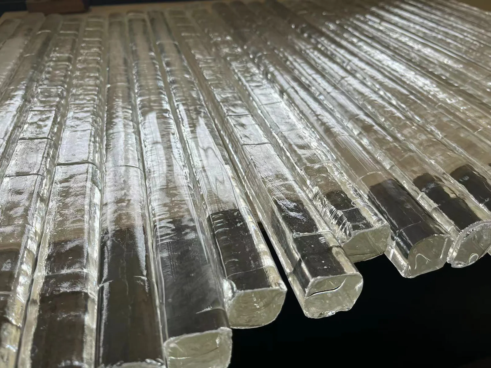
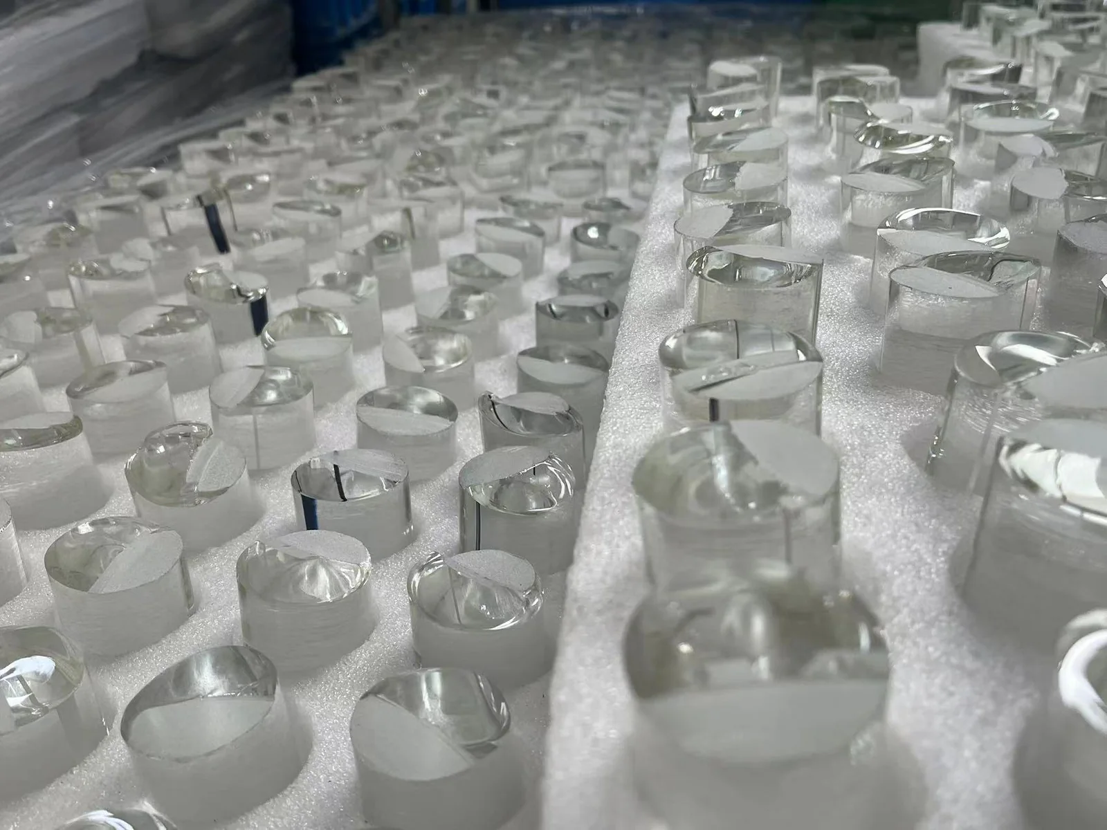
Specify or agree on the preform type, nominal geometry, mass or volume tolerance, surface condition, permitted defects and orientation. Confirm that its volume supports the finished component and intended mould-closing position.
The preferred preform may be a polished ball, gob, disc, blank or near-net-shape part. Selection should be made together with the intended moulding cycle and final geometry.
Start with the finished optical function
Optical design should begin with what the component must do inside the complete system. Focal length, numerical aperture, field of view, beam angle, working distance, spot size, transmission and sensor position can all influence the final lens geometry.
Define the conditions under which performance is expected. A nominal value alone is insufficient for manufacturing and verification if wavelength, temperature, conjugate distance or measurement method changes the result.
Before releasing the drawing, establish:
- Operating wavelength or spectral band
- Effective and back focal lengths, object distance and image distance
- Clear aperture, numerical aperture or f-number
- Field of view, distortion and image-quality requirements
- Beam angle or irradiance distribution where applicable
- Operating temperature and environmental conditions
- Mounting and coating requirements
Translate these system requirements into measurable component characteristics. The drawing should communicate both the nominal geometry and the acceptance criteria needed to protect the intended optical function.
Define the optical geometry without ambiguity
A moulding-ready data package must define every functional and mechanical surface without relying on interpretation. The supplier should be able to reconstruct the nominal component from the controlled drawing and digital data.
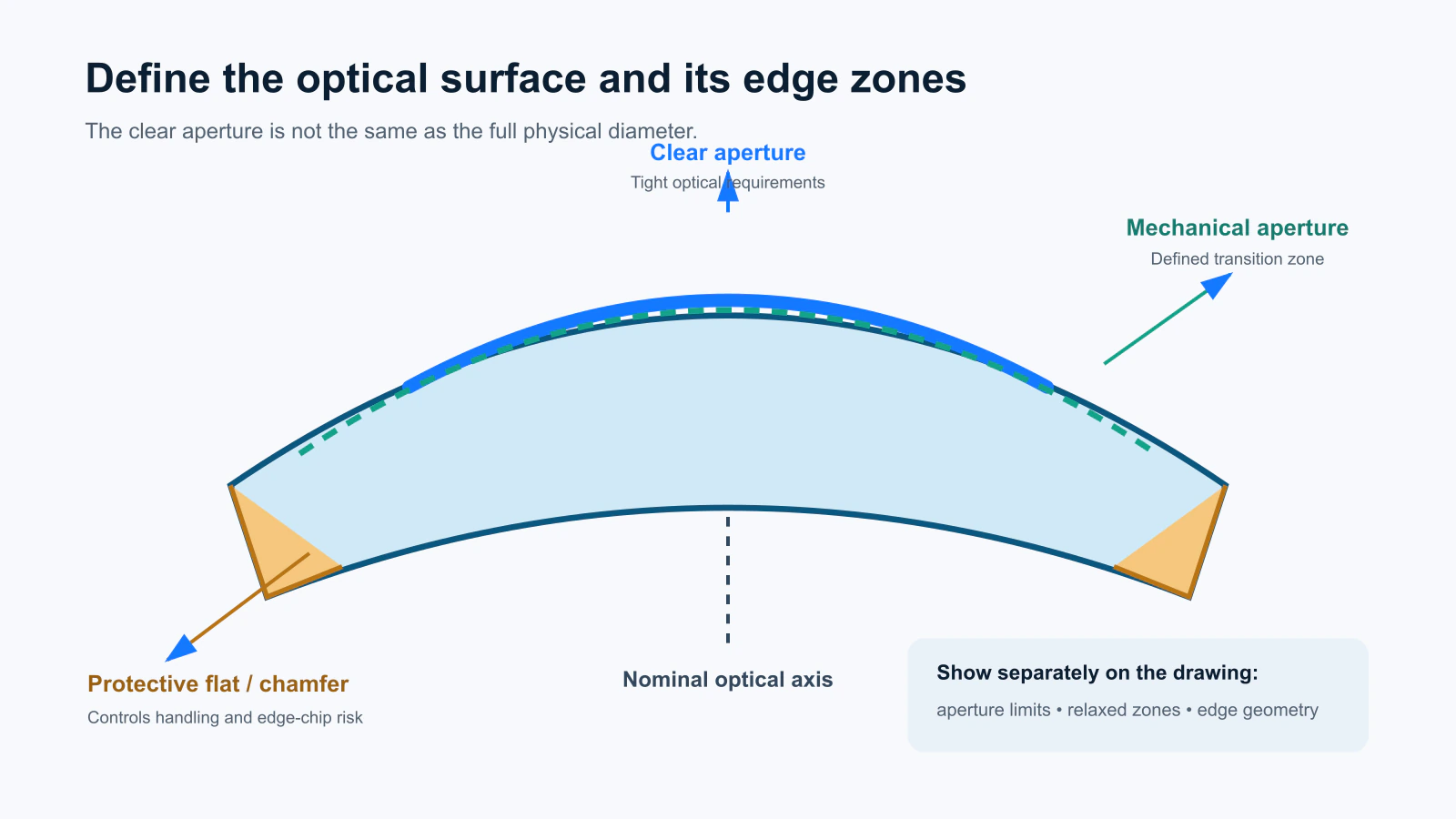
For a rotationally symmetric lens, define its diameter, centre and edge thicknesses, radii, sag, clear and mechanical apertures, edge transitions, locating features, datums and coating zones.
Centre thickness, edge thickness, diameter, sag and glass volume are connected. Tightening these values independently can create conflicting requirements, particularly when the final geometry is governed by preform volume and mould-closing position.
Clearly distinguish the clear aperture from the full physical diameter. If the surface outside the clear aperture permits relaxed form or cosmetic limits, show that zone and its acceptance criteria explicitly.
Specify aspherical and freeform surfaces
A spherical surface can normally be defined by radius, aperture and orientation. An aspherical surface also requires its base curvature, conic constant, polynomial coefficients, coefficient units, radial coordinate and sign convention.
For each aspherical surface, provide:
- Complete equation, vertex curvature, conic constant and coefficients
- Units, coordinate origin and positive axis direction
- Radial domain and clear aperture
- Maximum aspheric departure and local slope
- Sag table or point cloud where appropriate
- Approved 3D model and revision
The drawing, optical model, CAD model and inspection software must use the same equation and coordinate convention. Do not round coefficients during data transfer unless the retained precision has been verified against the permitted surface-form error.
Where ISO-based drawings are used, ISO 10110-12:2019 provides conventions for aspheric surfaces and surfaces with low-order symmetry. Off-axis aspheres and general non-symmetric surfaces should normally be described using an applicable general-surface method such as ISO 10110-19:2015, together with controlled digital surface data.[2]
Review departure, slope and curvature change
Two lenses with similar diameter and focal length can present very different manufacturing difficulty. Maximum aspheric departure and local slope are often more informative than the word “aspheric” by itself.
Large departure can increase compensation demand. Steep slopes and rapid curvature changes can complicate machining, coating, metrology, glass flow and release. Review maximum departure and slope, curvature change, edge thickness near steep regions, trapped-gas risk and access for machining and inspection.
Complex geometry is not necessarily unsuitable, but the surface definition, mould strategy and inspection plan must be reviewed together before tooling begins.
Design for filling, replication and release
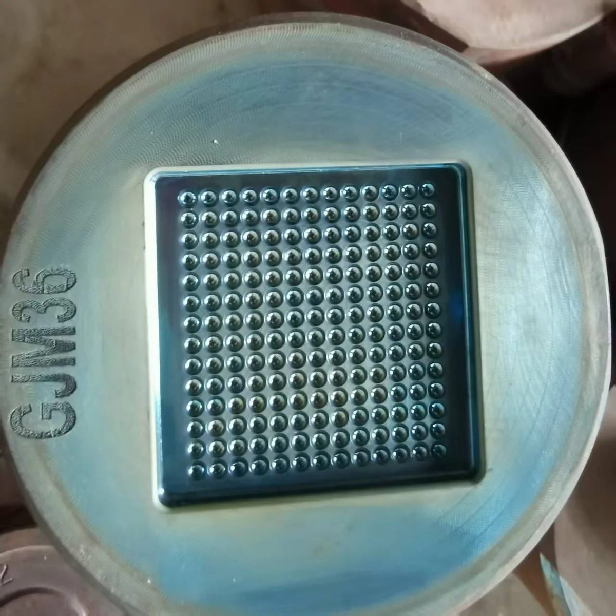
During moulding, the glass must contact and replicate the functional mould surfaces without folds, trapped gas, uncontrolled flash or unstable thickness. The finished component must then release without sticking, scratching or damaging the optical surface.
Pay particular attention to thin centre or edge regions, large thickness changes, deep concave surfaces, sharp transitions, isolated cavities, steep edge regions, undercuts, knife edges, discontinuous microstructures and features that obstruct release.
Avoid sharp optical transitions unless they are functionally necessary. Small radii, protective flats or controlled transition zones can improve filling and reduce edge damage, provided they remain outside the functional aperture.
Mechanical surfaces may include release allowances, but conventional draft should not be added automatically to a functional optical surface. Verify any geometry change in the optical model and against the assembly interface.
Protect the optical edge
The edge influences glass flow, mechanical strength, handling, centring and assembly. A theoretically sharp edge is normally vulnerable to chipping and difficult to reproduce consistently.
Replace generic notes such as “break all sharp edges” with a controlled specification. Define the chamfer, radius or protective flat; its relationship to the clear aperture; permitted chips; secondary finishing; required centring; and coating termination.
Optical and mechanical teams should approve the edge together. Increasing edge thickness can improve robustness but may change weight, mounting height and optical packaging.
Establish optical and mechanical datums
A moulded lens can meet the form tolerance of each surface and still fail in an assembly if the surfaces are not correctly centred or tilted relative to the mounting features.
Establish a datum system that connects the optical surfaces to the outside diameter, flange, seating face or other assembly interface. Use the same datum logic when defining the inspection setup.
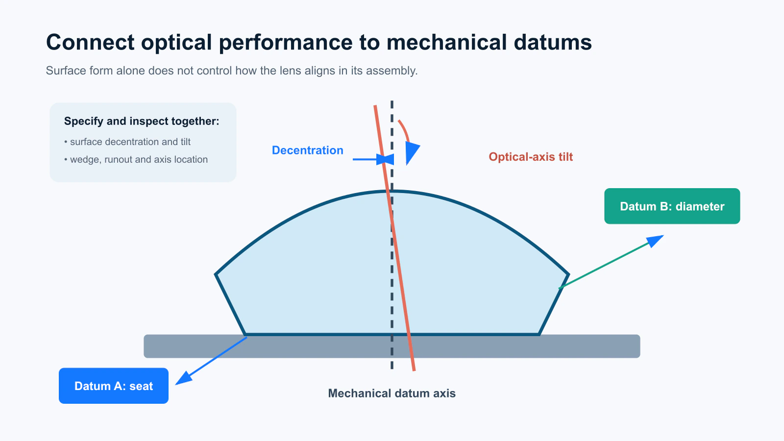
Relevant characteristics include surface decentration and tilt, wedge, optical-axis displacement, outside-diameter or flange runout, centre-thickness variation and alignment between optical and mechanical axes.
Do not use wedge, decentration, runout and centring error interchangeably. They describe related but different conditions and can require different fixtures and measurement methods.
ISO 10110-6:2025 provides rules for indicating centring and tilt tolerances, but the drawing must still identify the selected datums and inspection arrangement clearly.[3]
Connect tolerances to inspection
Optical surface quality is not one value. Separate requirements by spatial scale and functional effect.
| Characteristic | What it describes | Possible optical effect |
|---|---|---|
| Surface form | Low-spatial-frequency departure from nominal geometry | Power, focal position, wavefront and image quality |
| Waviness or mid-spatial-frequency error | Smaller-scale variation after nominal form is removed | Stray light, contrast loss and structured wavefront error |
| Surface roughness | High-spatial-frequency surface texture | Scatter, transmission and coating performance |
| Surface imperfections | Local scratches, pits, digs, chips or blemishes | Cosmetic rejection, scatter, durability or local damage risk |
Where applicable, use ISO 10110-5:2026 for surface-form tolerances, ISO 10110-8:2019 for surface texture and ISO 10110-7:2017 for surface imperfections. Identify the applicable edition and evaluation method in the controlled documentation.[4]
Use functional tolerances
Over-tolerancing increases tooling iterations, inspection time and rejection risk without necessarily improving system performance. Link every tight tolerance to an optical, mechanical, environmental or assembly function.
During tolerance review, identify which characteristics affect optical performance or assembly location, which values are coupled through mould closing or glass volume, which limits apply only inside the clear aperture, and whether the measurement system can resolve them. Also distinguish production acceptance limits from qualification-only requirements.
Surface form, focal length, centre thickness and centring can interact. Avoid tightening them independently without a system-level tolerance analysis.
Define the measurement method
A numerical limit is incomplete when different instruments, fixtures, filters or fitting methods can produce different results from the same component.
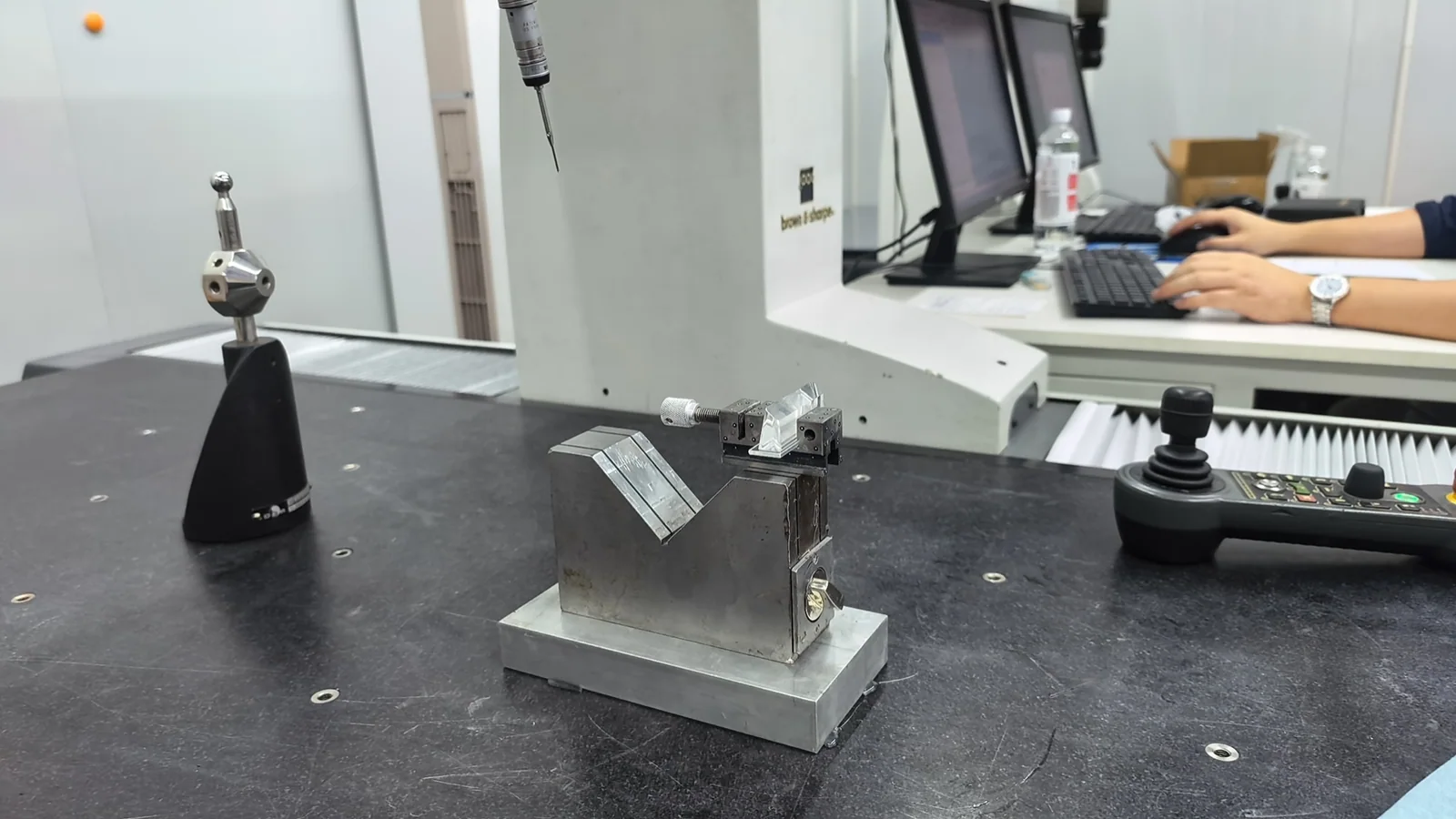
For critical characteristics, agree on the instrument and wavelength, datums, measurement aperture, support method, temperature, fitting method, removed terms, filtering, sampling, uncertainty and retest procedure.
For example, a surface-form result can change depending on whether piston, tilt or power is removed. Roughness depends on scan length, objective and filtering. Centring results depend on datum selection and the rotation method. Agree on these conditions before final tooling qualification, especially when customer and supplier measurements will be compared.
Plan mould compensation and process qualification
The mould surface is not always an exact negative copy of the nominal component. Glass contraction, mould expansion, pressing load, stress relaxation, temperature gradients and non-uniform cooling can change the geometry between forming and room-temperature inspection.
Some change may resemble uniform shrinkage. Aspherical and freeform components can show non-uniform deviation that requires local mould compensation.
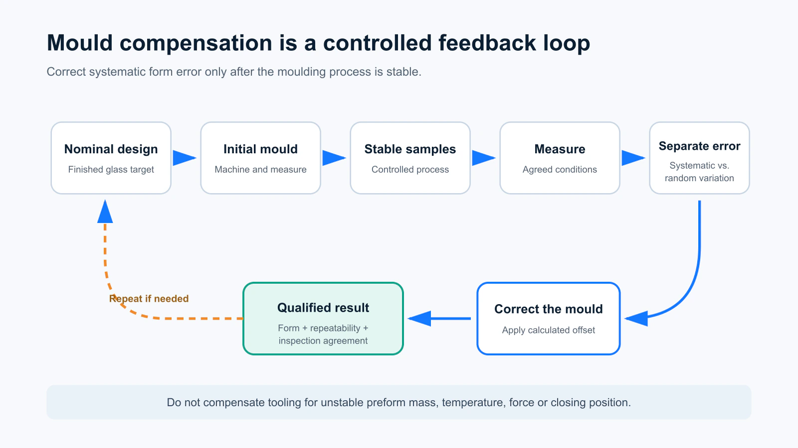
A controlled compensation loop normally follows this sequence:
- Manufacture and measure the initial mould inserts.
- Produce samples using a documented, stable process condition.
- Measure the finished glass and compare it with the nominal design.
- Separate systematic form error from random process variation.
- Calculate and machine the required mould correction.
- Repeat moulding and validation until the result is approved.
Compensation should be based on stable process data. Correcting the mould while preform mass, thermal cycle or closing position is still changing can transfer process variation into the tool geometry.
The customer drawing should therefore continue to define the required finished glass component. Compensated mould geometry is a manufacturing-controlled tool design derived from that specification.
Qualification should also confirm repeatability across multiple cycles and, where required, preform or glass lots. In addition to dimensions and surface form, review residual stress or birefringence, surface haze, sticking marks, folds, cracks, edge damage, coating performance and functional optical results.
Address application-specific requirements
The same nominal lens can need different acceptance criteria in different systems.
- Imaging optics: Surface form, centring, transmitted wavefront, focal length, distortion and imperfections within the clear aperture may be critical.
- LED and illumination optics: Beam angle, candela distribution, uniformity, colour consistency, stray light and efficiency may be more useful than imaging metrics alone.
- Sensor and detection optics: Spectral transmission, coating performance, thermal stability and optical-axis location relative to mounting features may control acceptance.
- Laser optics: Roughness, contamination, coating defects, wavefront error and laser-induced damage can be important. Define wavelength, pulse duration, repetition rate and beam conditions when specifying damage performance.
- Automotive and outdoor optics: Thermal cycling, humidity, chemicals, vibration and sealing may influence glass, coating, edge and mounting decisions.
Identify these requirements during optical design rather than adding them after the mould and process have been qualified.
From optical prescription to production release
Documents to provide
A complete technical package reduces uncertainty and prevents assumptions from becoming production requirements. Include:
- Controlled drawing, 3D model and optical prescription
- Surface equations, conventions and any required sag or point data
- Glass grade or approved alternatives
- Clear apertures, mechanical apertures and datums
- Dimensional, surface and alignment tolerances
- Functional, coating and environmental requirements
- Inspection method, reports, quantities and revision history
Define document precedence. If the drawing, model, sag table and optical file contain different nominal values, the supplier must know which source controls production and inspection.
DFM review gates
Before releasing the tooling, confirm that the glass and preform are appropriate, the geometry can fill and release, mould surfaces can be produced and measured, compensation is practical, tolerances match process capability, and secondary operations will not break the datum strategy.
Return any proposed geometry change to the optical model. A small manufacturing change can affect focal length, wavefront, beam distribution or assembly alignment.
Qualification workflow
- Define system-level optical and environmental requirements.
- Select the optical architecture, glass and preform route.
- Create the prescription and controlled component data package.
- Review filling, release, tooling, tolerances and inspection.
- Adjust non-critical geometry and establish the validation plan.
- Manufacture the mould and measure engineering samples.
- Apply compensation and validate repeatability.
- Freeze the drawing, tooling condition, process window and inspection method.
Common design risks
Common avoidable risks include:
- Selecting glass from refractive index alone and ignoring forming behaviour or thermal history
- Omitting preform mass, volume or surface-condition requirements
- Supplying inconsistent or excessively rounded aspheric coefficients
- Leaving the clear aperture, edge zone or datum structure undefined
- Specifying slopes or tolerances without confirming machining and metrology capability
- Tightening coupled dimensions independently
- Correcting the mould before the process is stable or adding requirements after tooling release
Resolving these questions before tooling is generally more effective than trying to correct them through inspection limits after samples have been produced.
Frequently asked questions
Can PGM produce finished optical surfaces?
Yes. It can produce the functional surfaces without subsequent grinding and polishing, although edge finishing, centring, coating or cleaning may still be required.
Is every optical glass suitable?
No. Forming temperature, viscosity, devitrification, chemical interaction and cooling response must be considered together with optical properties.
Why can the mould differ from the nominal lens?
Thermal contraction, mould expansion, stress relaxation and temperature gradients influence the final glass shape, so a compensated mould may be required.
Which tolerances should be prioritised?
Prioritise requirements that protect optical performance, assembly location or reliability, and ensure that every critical limit has a compatible inspection method.
Key takeaway
Precision glass moulding should be treated as a coordinated optical and manufacturing system. Lens geometry, glass and preform, mould design, thermal cycle, tolerances and inspection must support the same functional requirements.
A complete and internally consistent data package allows mouldability, tooling risk and measurement feasibility to be evaluated before tooling begins. Early design-for-moulding review can reduce tolerance conflicts, compensation iterations and production uncertainty.
Scope note: This guide provides general design guidance. Achievable dimensions, tolerances and surface quality depend on the selected glass, component geometry, mould system, production equipment and inspection method.
Related technical guides
References
- SCHOTT TIE-40 — Optical glass for precision moulding, including discussion of preforms and the effect of moulding thermal history on optical properties. ↩
- ISO 10110-12:2019 — Aspheric surfaces and ISO 10110-19:2015 — General description of surfaces and components. ↩
- ISO 10110-6:2025 — Centring and tilt tolerances. ↩
- ISO 10110-5:2026 — Surface form tolerances, ISO 10110-7:2017 — Surface imperfections and ISO 10110-8:2019 — Surface texture. ↩
Contact Us
Your feedback fuels our growth, and your questions drive our solutions.
We value your feedback, inquiries, and suggestions. Please feel free to get in touch with us
General inquiries
Please contact us via sales@bo-glass.com, and we will reply to you as soon as possible.
Interested to work with us
Drop your resume at info@bo-glass.com
and we will get back to you shortly.
We uses the contact information you provide to us to contact you about our relevent content, products, and services.