
← Back to the glass rod pressing technology guide
Precision Glass Moulding Defects and Troubleshooting
Identify the observed defect, check the evidence and verify that corrective action works without compromising other product requirements.
Defects can originate in the preform, tooling, forming cycle, cooling, release or subsequent processing. Similar appearances can have different causes: a local depression may involve incomplete contact, trapped gas, tool damage or glass pulled out during release. A focal deviation may involve geometry, material properties or the test setup.
This companion to the Precision Glass Moulding Design Guide addresses precision moulding with high-quality preforms and precision tooling. Acceptance depends on the drawing, optical and mechanical function, and agreed delivery condition. An intentional texture or peripheral feature is not a defect simply because it differs from a smooth optical surface.
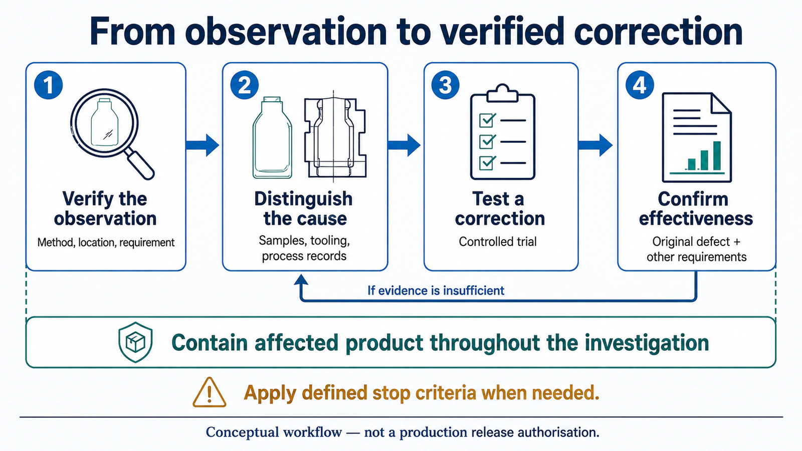
At a glance: Verify the observation, contain the relevant production population, distinguish plausible causes and test a defined correction. Appearance, correlation and one acceptable trial part do not independently establish the cause or justify routine production release.
Verify the Defect and Contain the Affected Population
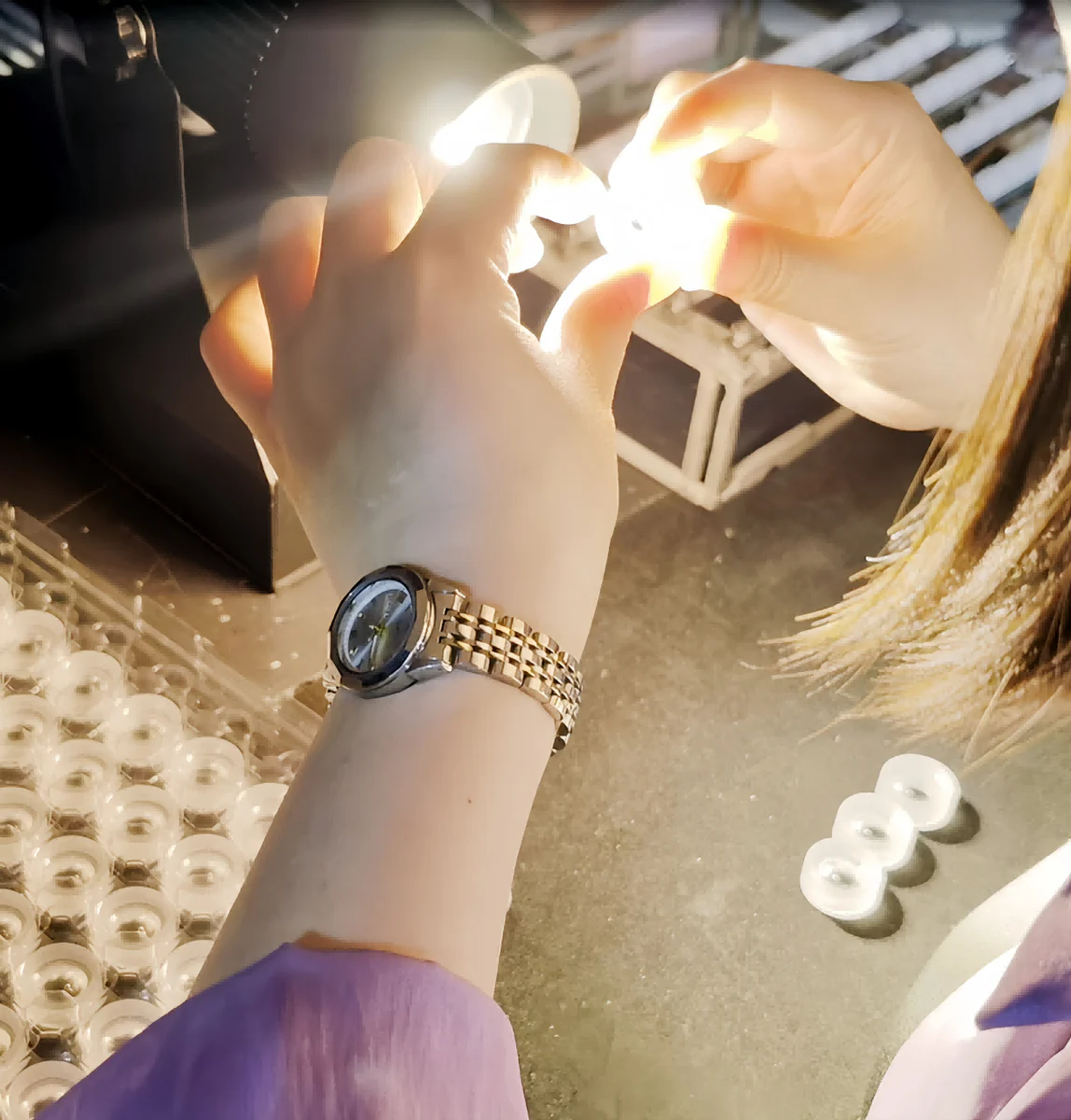
Describe the condition so that another inspector can reproduce the observation. Replace terms such as “poor surface” or “bad optics” with the affected location, size, distribution and departure from a requirement.
Keep a common investigation record:
- Part and drawing revision, material lot, cavity and tooling identity where applicable.
- Surface number, orientation and location relative to the clear aperture and datums.
- Inspection method, lighting, magnification and photographs with a scale.
- Measured quantity, result, limit and relevant uncertainty.
- Processing state, detection time, associated process records and recent changes.
For optical tests, also align wavelength, aperture, fixture, fitting terms and analysis convention. Repeat conflicting results using the agreed method; a reference component or controlled repositioning check can help separate part variation from measurement variation.
The first detection stage is not necessarily the origin. An earlier edge flaw may become visible only after a later load or operation.
Separate Containment from a Production Stop
Once a nonconformity is confirmed, use lots, cavity identity, timestamps, inspection checkpoints and tooling history to bound the potentially affected population. Do not assume that only visibly defective samples are affected.
Where a suspected defect risks further tool damage, component breakage or release of nonconforming product, apply the defined containment or stop criteria while verification continues. Root-cause confirmation is not a prerequisite for protecting the process and product.
Hold product release when conformity is unresolved; isolate potentially affected parts for evaluation; stop production when the applicable stop criteria are reached. These are different decisions, and not every cosmetic observation requires a machine stop.
Preserve representative acceptable and defective parts and document their condition before cleaning, reworking or tool maintenance removes evidence.
Use the Defect Map to Choose the First Check
Use this map to distinguish mechanisms before selecting a correction. The entries are investigation starting points, not diagnoses or prescribed machine adjustments.
| Observed symptom | First distinction to make | Evidence to check |
|---|---|---|
| Incomplete edges or poorly replicated features | Insufficient glass charge or inadequate local contact? | Preform mass and shape, defect location, forming endpoint and process traces |
| Surface-form or radius error | Repeatable deviation or changing result? | Nominal prescription, fitting convention, mould profile and cooling history |
| Thickness or diameter drift | Input variation, closure-reference change or thermal effect? | Preform measurements, displacement, load and stabilised dimensions |
| Wedge or centration variation | Part misalignment or fixture/datum error? | Optical-to-mechanical references, loading position, tooling and repositioning checks |
| Sticking or surface pull-out | Interface deterioration or unsuitable release conditions? | Matching glass and mould locations, coating history and release sequence |
| Scratches, pits or repeated imprints | Raised deposit, material loss or inspection artefact? | Microscopy or surface measurement, matching tool region and handling contacts |
| Haze or discolouration | Surface phenomenon or a change within the glass? | Reflection/transmission inspection, retained samples and downstream history |
| Dark spots, bubbles or voids | Internal feature or surface/interface defect? | Depth and morphology, incoming preforms and contact progression |
| Cracks or chips | Earlier damage activated later or damage introduced at that operation? | Preserved fracture evidence, contact locations, force events and stage samples |
| Wavefront, focal or beam failure | Test-condition change or component/assembly change? | Test configuration, geometry, material optical state and before/after results |
Incomplete Filling and Poor Surface Replication
Incomplete forming may appear as missing peripheral geometry, insufficient sag, local non-contact or poorly reproduced fine features, where specified. Distinguish insufficient glass charge from inadequate deformation or incomplete contact between the glass and the mould surface.
Compare actual preform mass and shape with the specified input. Review temperature, force, displacement and timing records, including whether the forming endpoint was reached and whether load rose unusually early.
A repeatable local defect calls for checks of contact progression, gas escape and tool geometry even when overall dimensions are reasonable. For preform-selection principles, see Optical Glass and Preform Selection.
If the charge is outside specification, restore the input and identify the affected material population. If the thermal state is unsuitable, investigate heating, sensor performance, soak timing and transfer delay where relevant. Changing a displayed temperature without resolving the actual variation may leave the problem unchanged.
For persistent local non-contact, evaluate the preform shape and contact sequence. Changes intended to improve gas escape must preserve the optical surface and other specified features.
Verification focus: Check the previously incomplete region, feature geometry and surface form, together with thickness and release damage. Higher force cannot supply missing material; improved filling is not sufficient if it introduces sticking or distortion.
Surface-Form, Radius and Waviness Errors
A stable deviation, cavity-specific difference and within-run drift suggest different investigations. Stable errors may involve mould geometry, coating contribution, thermal compensation or the measurement definition. Variation may involve thermal state, positioning, process transitions or tool condition.
Confirm the Geometric Comparison
Check the surface prescription, units, coordinates, orientation, aperture and fitting convention. Best-fit radius or power subtraction can conceal an absolute geometric deviation; distinguish that requirement from residual irregularity.
Compare part and mould maps where practical, accounting for their opposing surface orientations and coordinate correspondence. A repeated pattern is useful evidence only when the maps refer to matching locations.
Stabilise the Process Before Compensation
Cooling can change the final profile and residual stress, so review thermal and restraint conditions before changing the mould prescription. Liu and Zhang (2015): Thermoforming mechanism of precision glass moulding
Correct alignment or reference errors first. Base surface compensation on repeatable residual deviation under a stable process, not on an average that hides changing behaviour.
For waviness or periodic marks, compare spatial patterns with tool measurements and process behaviour. Confirm improvement over the required aperture rather than along one favourable profile, retaining the specified filtering and reported metric.
Thickness, Diameter, Wedge and Centration Variations
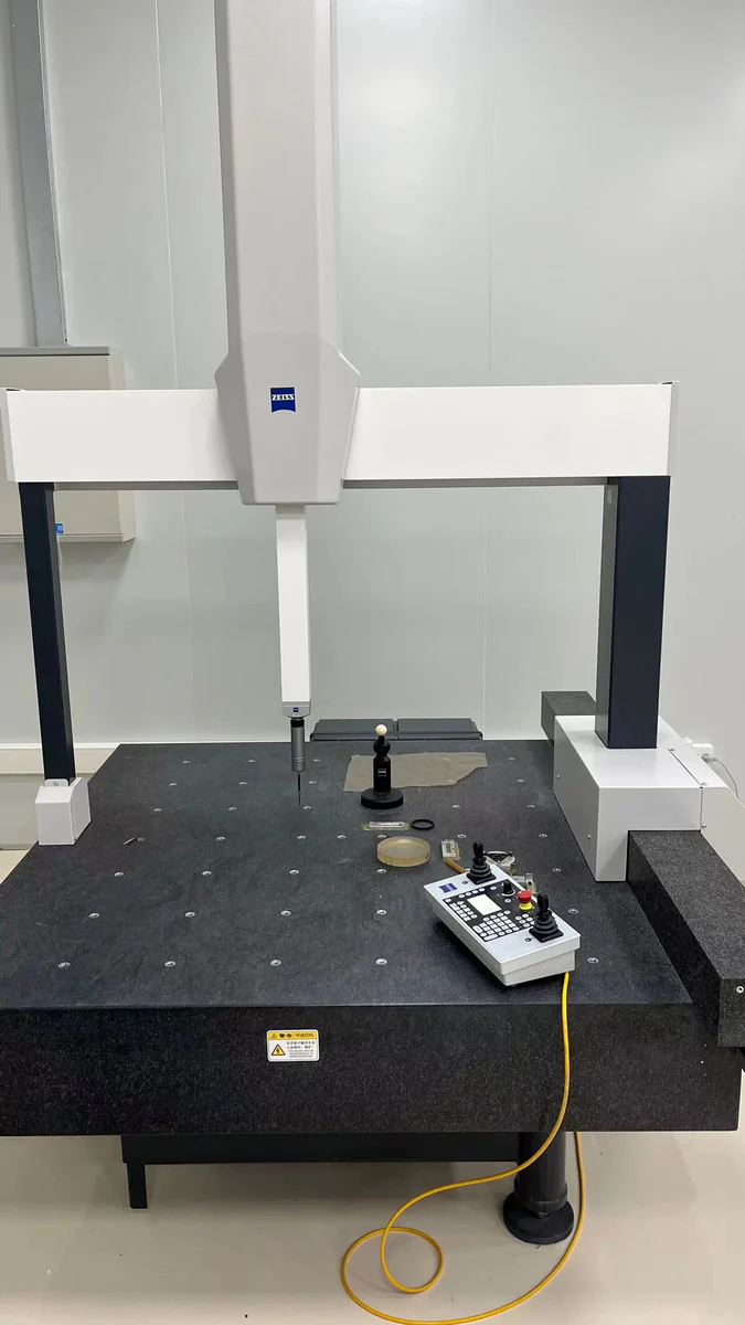
Final ram position is not automatically finished centre thickness. Machine compliance, tooling expansion, mould deflection and cooling contraction affect that relationship.
Compare dimensions with preform mass, forming displacement and load history. Depending on the tooling, excess glass can change peripheral geometry, prevent intended closure or increase load. Do not automatically correct thickness by changing the closing position.
Evaluate peripheral material against the delivery condition: planned trimming allowance differs from an out-of-tolerance finished edge.
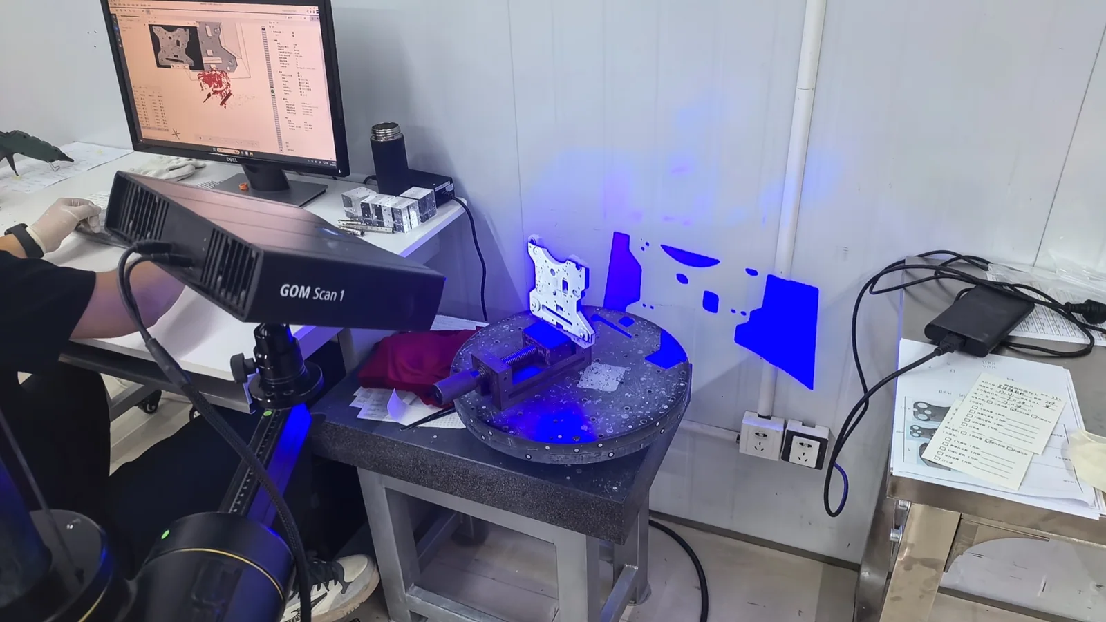
For wedge and centration, examine optical surfaces relative to the specified mechanical datums. Review preform seating, upper/lower tooling alignment and the inspection fixture. Freeforms require the prescribed orientation and coordinates; a centred outside diameter alone does not establish optical centration.
Restore the identified input, assembly or reference condition before broader recipe changes. Verify dimensions with form and alignment, retaining cavity identity so that an improved average does not conceal one cavity's remaining problem.
Sticking, Difficult Release and Coating Deterioration
Increased release resistance, transferred glass, local pull-out or defects growing over successive cycles require examination of both sides of the interface: the glass and corresponding mould region.
Research on specific PtIr protective coating systems has observed interdiffusion, oxidation, spallation and glass sticking. These findings support investigating coating, thermal and atmosphere history together; they do not establish the same failure mechanism for every coating system. Friedrichs et al. (2019): PtIr protective coating degradation
Record tool and coating identity, maintenance history, glass grade, actual temperatures, accumulated hot exposure, chamber-atmosphere records and the unloading/opening sequence. Distinguish the mould's release coating from an optical coating applied later to the glass.
Document transferred material before maintenance. A contaminated or damaged insert may need qualified cleaning, refurbishment, recoating or replacement; the route must preserve its geometry and surface condition.
Review temperature, contact time and release conditions within the established process range. Increasing extraction force does not correct an unsuitable interface and may increase damage. Apply the defined stop criteria rather than waiting for complete sticking.
After intervention, inspect the tool and trial parts. If deterioration previously developed over repeated cycles, an initial clean release is insufficient: the confirmation run must address recurrence as well as form, roughness and dimensions.
Scratches, Pits, Tool Marks and Surface Imprints
First establish whether the feature is a raised deposit, depression, scratch or measurement artefact using suitable microscopy or surface measurement.
A mark at fixed part coordinates suggests a repeatable contact mechanism: the mould, locating features, handling equipment or a downstream fixture. Random distribution may direct attention towards contamination, variable preforms or handling. Neither pattern alone proves the cause.
Inspect corresponding tool regions and retained preforms. If a mark is detected only after cleaning, coating or packaging, compare identified samples before and after that operation under consistent inspection conditions.
Remove the demonstrated source through appropriate maintenance or handling changes. Tool polishing can alter the optical prescription and require requalification. Polishing the glass can likewise change form, thickness and coating condition; do not treat it as an automatic cosmetic repair.
Verify that the feature no longer recurs without new roughness, form error or contact damage. Keep evidence of the original location so that a changed viewing direction does not create a false improvement.
Haze, Cloudiness and Discolouration
These terms describe appearance, not a unique mechanism. Possible explanations include deposits, replicated roughness, interface reactions, damage, material changes or crystallisation. A subsequent optical coating may also change appearance.
Inspect in reflection and transmission to locate the effect on one surface, both surfaces or within the glass. Compare incoming, moulded and downstream samples. An approved cleaning comparison can help identify removable contamination, but preserve unaltered evidence for further analysis.
Confirm Suspected Devitrification
Devitrification is crystalline material forming from glass; cloudiness alone does not establish it. Microscopy and suitable phase-sensitive analysis may be needed. Elemental analysis can identify composition but does not by itself prove crystallinity.
Resistance to devitrification and interaction with mould materials are glass-selection considerations. SCHOTT TIE-40: Optical glass for precision molding
Address the demonstrated mechanism rather than choosing a generic “haze correction”. Check relevant roughness, transmission, scattering and functional requirements after intervention; cleaner appearance does not resolve a remaining optical failure.
Bubbles, Voids and Inclusions
A transmitted-light dark spot may be an internal bubble, inclusion, surface pit, deposit or viewing effect. Establish depth and morphology before changing the process.
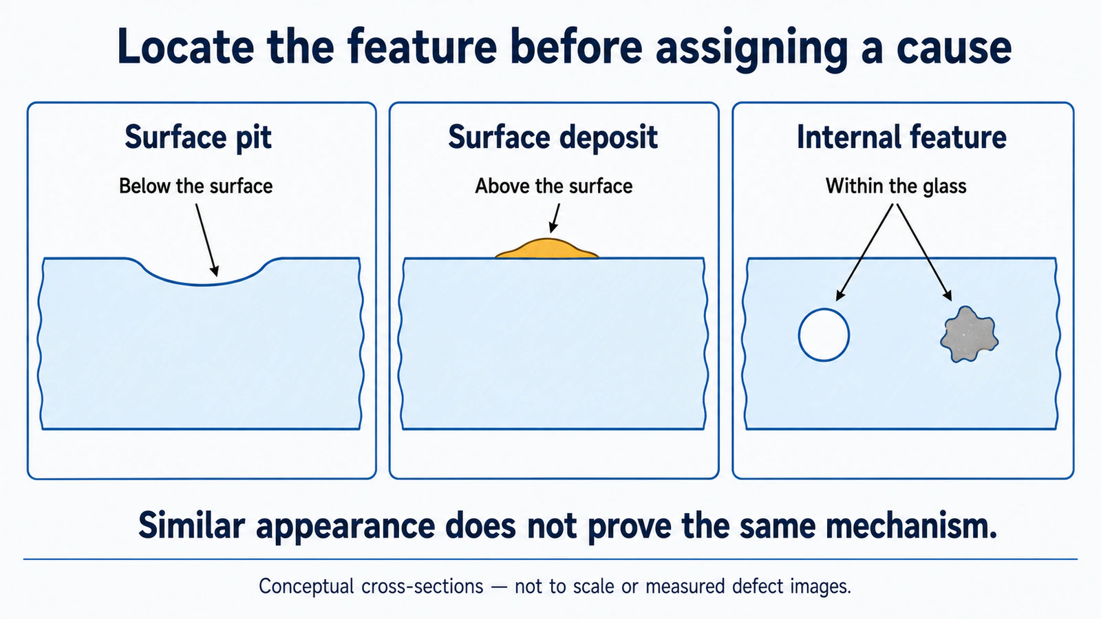
Review incoming inspection and retained preforms. An inherited internal feature requires a different investigation from a local surface depression caused by incomplete mould contact.
Gas trapped at the glass–mould interface can interfere with filling. A study of microlens-array moulding in nitrogen investigated this mechanism and a multistep forming method. Its geometry, material and process conditions do not define a universal remedy. Zhou et al. (2023): Gas trapping during microlens-array moulding
For inherited defects, review material specifications, inspection coverage and the affected lot. For suspected interface entrapment, investigate contact progression, chamber conditions and the gas-escape path through controlled trials of relevant changes.
Chamber evacuation should not be assumed to remove gas already enclosed within a preform. Check the relevant surface and internal volume after correction, together with sticking and distortion that revised contact conditions could introduce.
Cracks, Edge Chips and Fracture
Investigate both the applied loading and the glass condition. Thermal gradients, differential expansion, contact and pre-existing surface damage can contribute. Geometry, support and surface condition matter when evaluating thermal loading. SCHOTT: Thermal loading and glass strength
Record damage relative to edges, optical surfaces and fixture contacts. When fracture analysis is needed, retain representative fragments and preserve fracture surfaces; a final crack-pattern photograph may not establish the origin.
Use stage samples to distinguish loading, forming, release, cleaning, edge processing, coating, assembly and transport. A crack found at release may combine an earlier flaw with release load; breakage after assembly does not independently prove a moulding cause.
Compare the damage with force events, seating errors, cooling conditions, release resistance and downstream contacts. Include operations that could introduce surface or subsurface damage.
Correct the identified condition and assess the affected population. Routine stress-relief annealing is not a qualified repair for cracks. Edge chips outside the clear aperture still require evaluation against mounting, strength, dimensions and the drawing; their optical location alone does not make them acceptable.
Residual Stress and Functional Optical Failures
An optical failure may have no obvious visible defect. Start with the common measurement record and confirm the specified acceptance state: unmounted, coated or assembled, as applicable.
Stress Birefringence
Check wavelength, light path, orientation and fixture pressure. Retardation in nm, normalised retardation such as nm/cm and mechanical stress in MPa are different quantities; conversion needs appropriate material data and a valid interpretation of the stress state. SCHOTT TIE-27: Stress in optical glass
For a confirmed failure, review the complete thermal and restraint history. Evaluate cooling or annealing changes against form and functional performance, not birefringence alone.
Wavefront, Focal and Beam Performance
Align reference wavefront, single/double-pass configuration and focus convention. Compare both surfaces, thickness, wedge and alignment before assigning a deviation to material properties.
Thermal history can change refractive index relative to its reference condition, but a focal result alone does not uniquely identify that change. SCHOTT TIE-40: Optical-property changes after moulding
For imaging, check conjugates, aperture, field, spectrum and whether results share a common image plane or use independently optimised focus. For illumination, check source geometry, emitting area, position and operating condition: a changed source can change the beam without a glass change.
If transmission or other performance fails after coating or assembly, compare the relevant before/after states and include coating, mounting and alignment. Detailed acceptance methods are covered in Thermal Cycle, Cooling and Optical Performance Validation.
Find Patterns Across Cavities, Lots and Time
Group results by cavity, material lot, tool identity, production time and processing stage rather than pooling all defects into one rate.
| Observed pattern | Investigation direction |
|---|---|
| One cavity repeatedly differs | Local tooling, temperature, alignment, loading or release |
| All cavities change together | Shared material, machine, atmosphere or programme changes |
| Quality drifts during a run | Thermal evolution, deposits, wear, measurement drift or input variation |
| Problems concentrate at startup/restart | Stabilisation, interrupted-cycle handling and startup acceptance |
| One mark repeats at a fixed location | Repeatable mould, fixture or handling contact |
| Defects correlate with one material lot | Preform condition plus any simultaneous production changes |
| Failure is first detected downstream | That operation's loads, thermal exposure, cleaning and inspection conditions |
Correlation prioritises checks; it does not establish causation. A glass-lot change may coincide with tool maintenance. Compare both before attributing the issue to the supplier.
Keep the denominator and inspection basis comparable when reviewing rates. Changed sampling or sensitivity can change recorded defect rates without a production change.
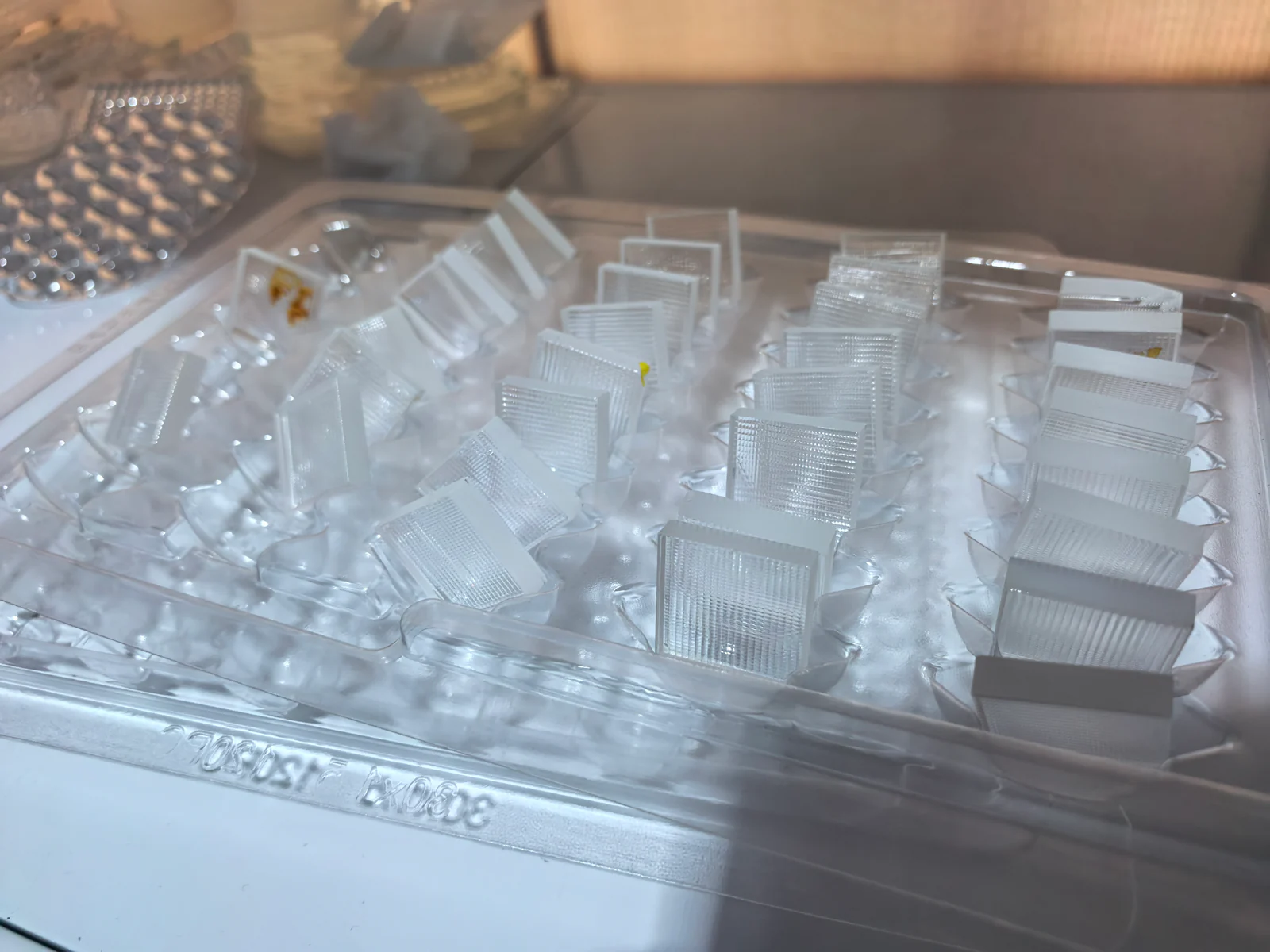
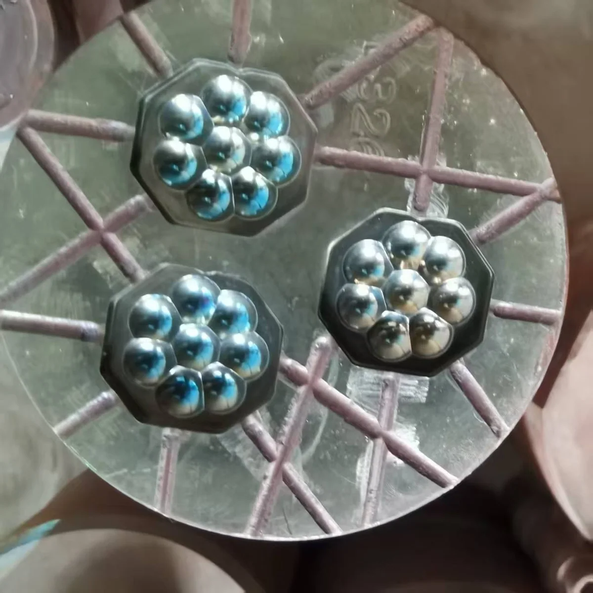
Test the Cause and Validate Corrective Action
Define a suspected mechanism, supporting evidence, proposed change and measurable outcome. A corresponding tool feature, preform deviation or repeatable trace change can support the explanation; specify what result would contradict it as well.
Establish a baseline and document trial conditions. Changing one relevant factor can help a focused check; where interactions matter, a designed experiment can assess factors together. NIST: Two-level full factorial designs
Account for progressive wear and machine warm-up so that test order does not masquerade as a parameter effect. Avoid several undocumented changes in one trial.
Define the Confirmation Run Before Testing
One acceptable part is limited evidence. Choose the confirmation scope from the failure mechanism and proposed production conditions:
- Include affected cavities and relevant material/input variation.
- Cover startup and stable operation when the issue depends on thermal state.
- Include sufficient continued cycling to assess an observed accumulation or wear-related recurrence.
- Include maintenance/restart conditions when those triggered the original issue.
- Define inspection coverage, acceptance criteria and the response to recurrence before judging results.
There is no universal confirmation quantity. Document why the selected scope addresses the observed variation and the risk of recurrence.
Check the original failure together with other critical requirements. Improved filling can increase sticking; reduced birefringence can accompany a form change; rework can alter thickness or optical power.
If evidence remains inconclusive, retain appropriate containment and distinguish a temporary adjustment from a demonstrated corrective action.
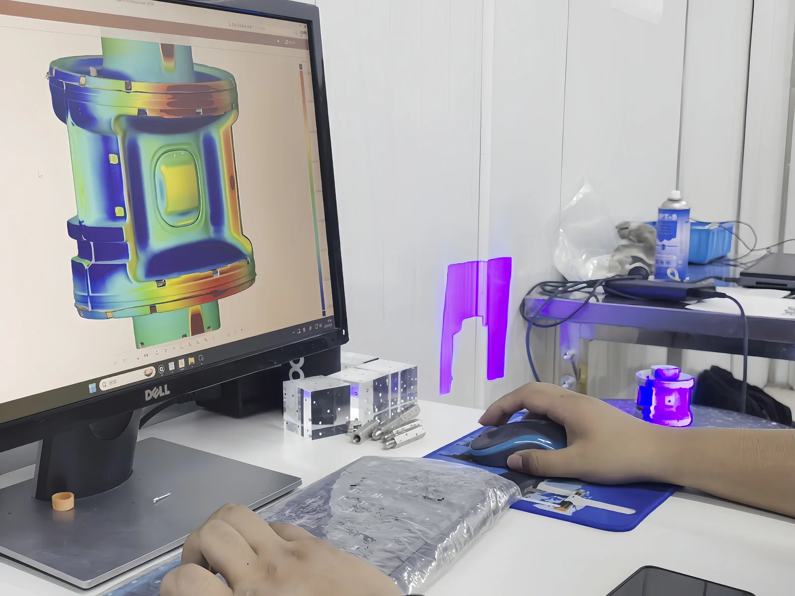
Control Rework, Restart and Recurrence
Give affected parts a documented disposition: validated cleaning or rework, further evaluation, an authorised concession where applicable, or rejection. Improved appearance alone does not establish conformity at the delivery state.
Cleaning must remove the relevant contamination without damage. Polishing, edge processing or remoulding can alter geometry, surfaces and thermal history; any such route requires qualification and subsequent inspection.
Separate Trial Operation from Routine Release
A controlled verification run may be needed to gather evidence. Identify its parts and keep their release status controlled while the correction is evaluated. Permission to run that trial is not automatic approval for unrestricted production or shipment.
Before routine restart and product release, confirm tooling/equipment and material status, the implemented action and recipe revision, first-off results and the required confirmation-run evidence. Record who authorises restart and how previously affected parts are dispositioned or remain controlled.
Address Both Creation and Escape of the Defect
Update the control that prevents the demonstrated cause and, where applicable, the reason existing checks failed to detect or contain it. This may require changes to incoming inspection, cleaning, maintenance criteria, loading, process limits or downstream fixtures.
An inspection change may concern timing, coverage, sensitivity or response to a failed result. Keep the action linked to the evidence, with traceability between the investigation and revised production documents.
Frequently asked questions
Can a Defect Cause Be Confirmed from a Photograph?
A photograph can establish appearance and location, but usually needs supporting measurements, representative samples and production records to distinguish depth, mechanism and origin. Do not treat a visual resemblance as a confirmed diagnosis.
Should Forming Force Be Increased When Features Are Incomplete?
Only when evidence supports it. Missing material, unsuitable thermal state or incomplete contact can require different corrections; any force adjustment must preserve the other quality requirements.
Are Defects Outside the Clear Aperture Acceptable?
Not automatically. Peripheral features can affect mounting, sealing, strength, dimensions or later processing. Evaluate the drawing and function, not optical location alone.
Why Can a Defect Return After Cleaning or Maintenance?
The intervention may remove an accumulated effect without eliminating its source. Investigate recurring contamination, tool/coating condition and restart controls, and compare the subsequent trend rather than only the first clean part.
Contact Us
Your feedback fuels our growth, and your questions drive our solutions.
We value your feedback, inquiries, and suggestions. Please feel free to get in touch with us
General inquiries
Please contact us via sales@bo-glass.com, and we will reply to you as soon as possible.
Interested to work with us
Drop your resume at info@bo-glass.com
and we will get back to you shortly.
We uses the contact information you provide to us to contact you about our relevent content, products, and services.