
← Back to the glass rod pressing technology guide
Mould Design, Tooling and Release-Coating Control
The mould is the optical master of a precision glass moulding process. Its geometry, alignment, thermal behaviour and coating condition influence every component produced from it. Accurate inserts are essential, but stable replication also depends on how those inserts are supported, coated, assembled and maintained.
This guide focuses on keeping surface form, alignment and release performance under control through repeated forming cycles. For finished-component requirements, see the Precision Glass Moulding Design Guide. Glass screening and preform selection are covered separately in Optical Glass and Preform Selection for Precision Glass Moulding.
At a glance: Qualify the glass, mould substrate, coating and process as one system. Establish operating-temperature clearances, measure the insert before and after coating, correct alignment before surface compensation, and define intervention limits before production begins.
Tooling requirements and design inputs
Start from the approved finished-component specification, not a simple negative copy of its nominal optical surface. The finished glass is defined at a reference temperature; the tool must account for its own expansion, glass contraction, process deformation and the deposited coating.
Group the essential inputs into four controlled packages:
- Optical definition: prescription, surface equations, apertures, form and texture limits, and optical-to-mechanical datum relationships.
- Mechanical definition: drawing, model, thicknesses, outside diameter, edge geometry and any secondary-finishing allowance.
- Material and process: glass grade, preform mass and geometry, forming equipment, atmosphere and preliminary thermal cycle.
- Acceptance and production: inspection methods, sampling plan, required output and traceability requirements.
Resolve disagreements between the drawing, model and sag table before manufacturing. Identify the controlling document, revision, coordinate convention and units. An apparently small mismatch in an aspheric definition can invalidate an otherwise accurately manufactured insert.
Distinguish finished-part tolerances from tooling acceptance limits. They are related through process behaviour and the optical error budget, but they are not automatically identical. Record whether an insert specification applies before coating or to the final glass-contact surface.
The design review should also identify inaccessible surfaces, uncertain material data and measurements that require special fixtures. Resolving these issues before machining is generally easier than discovering that a completed insert cannot be inspected consistently.
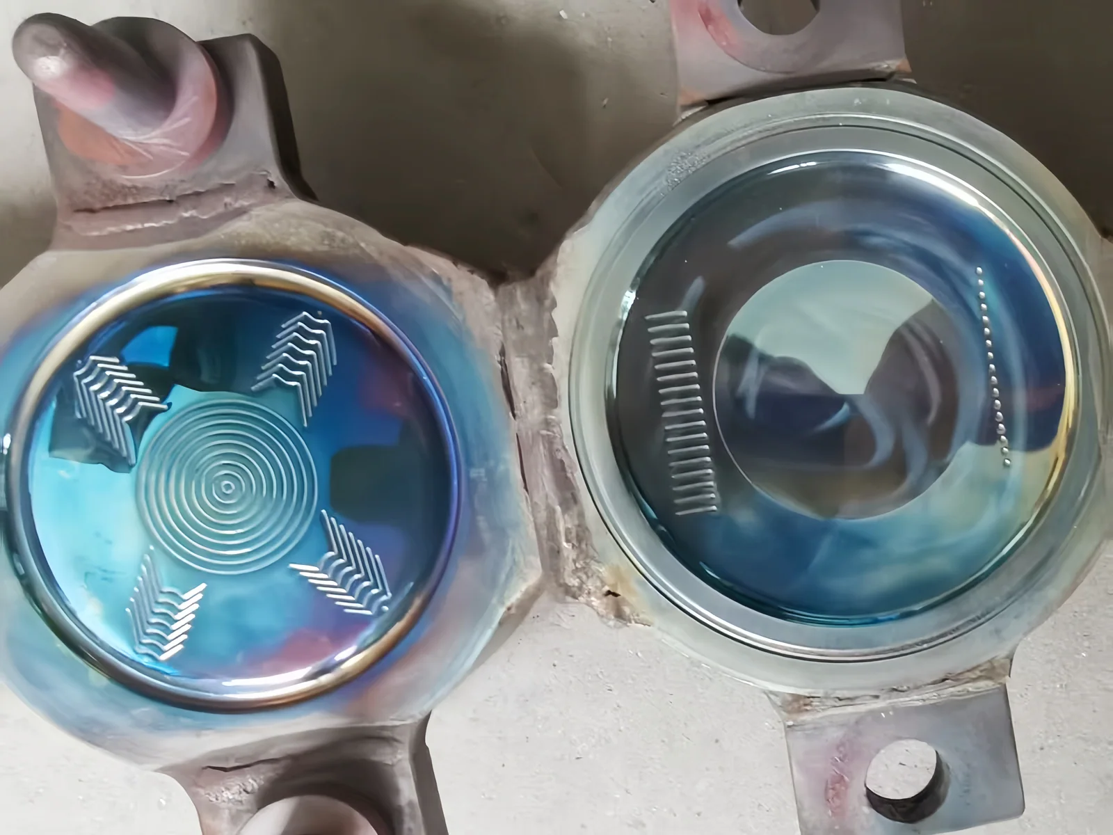

Mould architecture, datums and alignment
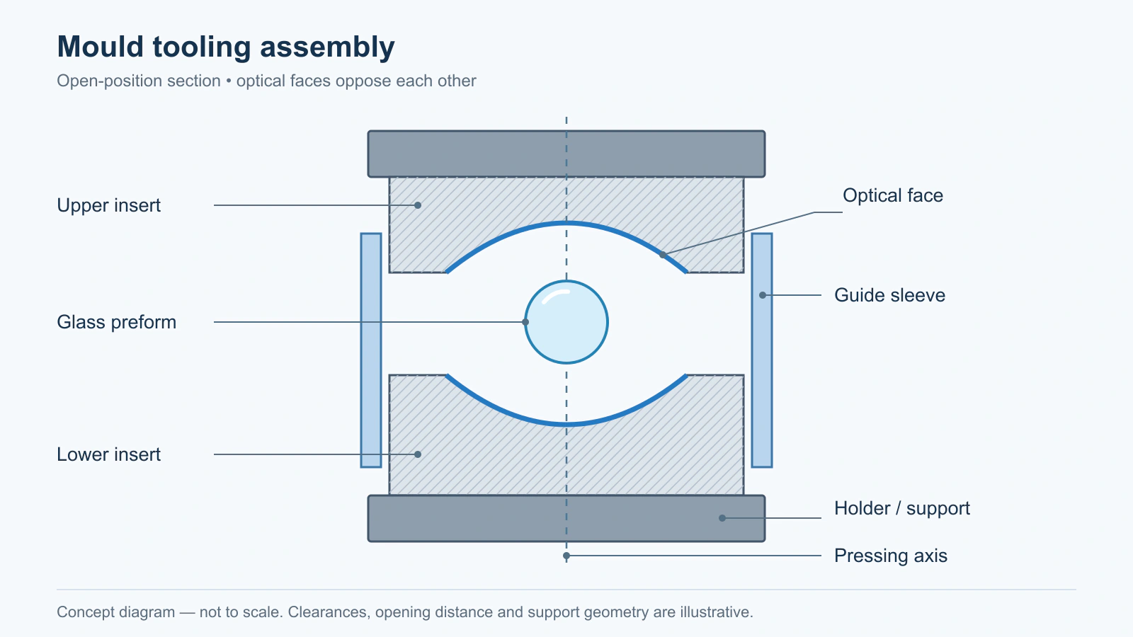
Treat the mould as an assembly: upper and lower optical inserts, holders, guide sleeves, axial stops, loading features and machine interfaces. Each element needs a defined locating, supporting or thermal function. Assembly and removal should be possible without touching the optical surfaces.
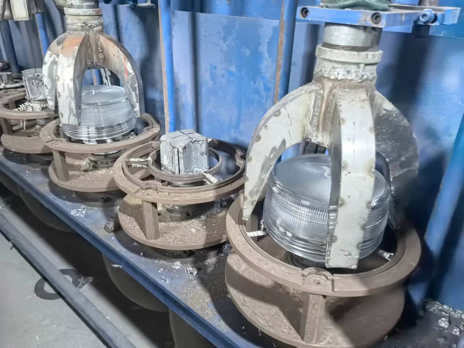
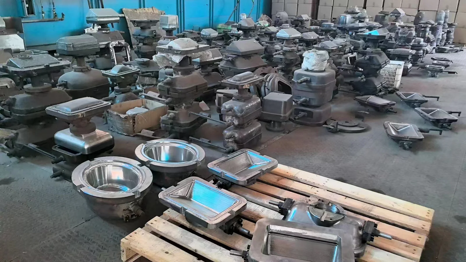
Single-cavity tooling simplifies alignment, compensation and defect diagnosis. Multi-cavity tooling can increase output, but it introduces cavity-specific differences in temperature, load, preform placement and coating wear. Approve each cavity from its own measurements and production results, not only the average across the tool.
Define how radial position, axial height and tilt are controlled through the complete stack. A close fit between an insert and sleeve does not establish optical alignment unless the optical surface is also centred to the insert's mechanical datum. Use inspectable locating faces and diameters, and minimise unnecessary transfers between manufacturing and measurement references.
Coating or contamination on a locating face can change stack height or alignment. Specify which surfaces are coated, masked or protected, and verify the resulting fits. Check alignment after initial assembly, coating, insert replacement and significant maintenance.
For freeform or other non-rotationally symmetric surfaces, angular orientation also matters. Use an indexed reference that remains identifiable during machining, coating, assembly and inspection. Record upper and lower insert identities as a matched configuration where their combined performance is qualified.
Mould-insert materials
Select the substrate for the actual glass, temperature, load, atmosphere, surface geometry and coating process. Hardness alone is insufficient: the material must be manufacturable to the required optical quality and remain compatible with the complete thermal cycle.
The following matrix is a screening aid, not a universal ranking or a statement that every listed material suits every precision moulding application.
| Material | Selection rationale | Main limitations | Qualification checks |
|---|---|---|---|
| Cemented tungsten carbide | High stiffness and hardness; established precision grinding and polishing routes | Brittle edge damage; grade-dependent binder, porosity and surface behaviour | Exact grade, binder, microstructure, finished texture and coating compatibility |
| Silicon carbide and selected ceramics | Candidates for demanding thermal conditions and specialised surfaces | Difficult finishing; brittle fracture; grade-dependent porosity and repair options | Manufacturable geometry, defect population, thermal behaviour and coating adhesion |
| Metallic or plated systems, including nickel-based options | Machining flexibility where the operating conditions permit use | Temperature-dependent structural change, deformation and expansion mismatch | Substrate and layer stability, machining allowance and repeated-cycle performance |
| Glassy carbon and other specialised carbon systems | Application-specific options for compatible glasses and structured surfaces | Atmosphere sensitivity and material-dependent strength, texture and handling limits | Exact material structure, optical finish, oxidation control and cycle testing |
Do not treat glassy carbon and graphite as interchangeable specifications. Likewise, “tungsten carbide” alone does not define a reproducible insert material. Record the approved grade and supplier, with any relevant batch requirements.
Evaluate the substrate and coating together. A material that machines well may be unsuitable if the deposited layer cannot adhere reliably or the assembled tool loses dimensional stability. Select a route that can be measured, maintained and reproduced, rather than one justified only by a favourable catalogue property.
Thermal clearances and insert support
The inserts, sleeve, holders and machine interfaces expand during heating. Different expansion behaviour changes radial clearance, axial stack height and locating contact. A fit that works at room temperature may bind or lose useful guidance during moulding.
Calculate the assembly condition across the relevant temperature range, accounting for the temperatures actually experienced by individual components. Use appropriate expansion data rather than extending a single room-temperature value without justification. Evaluate tolerance extremes as well as nominal dimensions, including the effects of coating on functional fits.
Support the loaded region sufficiently to limit bending while avoiding concentrated contact stresses. Insert thickness, locating shoulders, support area and thermal contact all influence behaviour. Thin inserts may heat quickly but deflect more; thicker inserts increase stiffness while adding thermal mass. Neither choice is automatically preferable.
Finite-element analysis can help assess load-induced deformation, temperature gradients and contact behaviour when the risk warrants it. Its usefulness depends on realistic boundary conditions, temperature-dependent properties and support assumptions. Compare predicted behaviour with measured parts before using the model to justify compensation.
Check the complete heating and cooling sequence, not only the nominal pressing temperature. Tooling must retain acceptable alignment during forming and allow safe release and disassembly afterward. Confirm that overflow cannot enter the clearances on which this movement depends.
Preform positioning, glass flow and venting
The interface between preform and tool determines where contact begins and how glass and gas move as the mould closes. An unstable loading position can produce asymmetric flow even when the inserts are correctly aligned.
Use locating pockets, rings or loading fixtures only where they do not create unacceptable imprints or obstruct forming. Check placement at the extremes of preform diameter, height and edge shape. A feature that centres the nominal preform may constrain an oversized one or fail to locate an undersized one.
Review the filling path through steep surfaces, thin regions and flanges. Late-filling regions may remain incomplete while other areas are already formed. Increasing pressure alone can introduce additional deformation or wear; review preform geometry, viscosity, closing motion and cavity design together.
Gas needs an escape route as contact spreads. Place venting features outside critical optical areas where practical, and evaluate whether they allow unwanted glass entry or witness marks. Concave pockets and isolated microfeatures require particular attention, but the design should be justified for the specific geometry rather than through a generic vent dimension.
Define the edge and overflow strategy explicitly. Planned reservoirs or secondary-finishing allowances can accommodate controlled excess glass; guide gaps and locating joints cannot. Keep the clear aperture separated from the parting region, and specify which edge features are moulded and which are finished afterward.
Optical-surface manufacturing and metrology
Choose the manufacturing route from both the substrate and geometry. Precision grinding, polishing and appropriate ultra-precision machining methods have different material, slope and access limitations. Being able to generate the nominal shape does not prove that its texture, local defects or measurement accessibility are acceptable.
Separate form, waviness, roughness and local imperfections. Form describes departure from the prescribed geometry. Waviness and mid-spatial-frequency structure can reflect machining paths or vibration. Roughness describes finer texture, while scratches, pits, pull-outs and chips require separate evaluation. A satisfactory average roughness does not make a local optical defect acceptable.
Define measurement aperture, datum, evaluation parameter, filtering and removed terms. Without these, two reports can give different results for the same surface. Preserve raw maps where practical, so later coating and wear measurements can be compared on a consistent basis.
| Stage | Characteristic | Measurement record | Acceptance basis |
|---|---|---|---|
| Before coating | Form, texture, local defects and mechanical datums | Surface maps, dimensional report, instrument and evaluation settings | Approved substrate geometry and tooling limits |
| After coating | Glass-contact form, texture, coverage and locating surfaces | Comparable maps, microscopy and qualified coating measurements | Coated-tool specification and allocated error budget |
| After assembly | Relative position, tilt and closing configuration | Alignment report and identified insert stack | Assembly requirements and machine interface limits |
| During qualification | Finished-part optics, dimensions and release stability | Cavity-specific results linked to recipe and cycle history | Component acceptance criteria and validation plan |
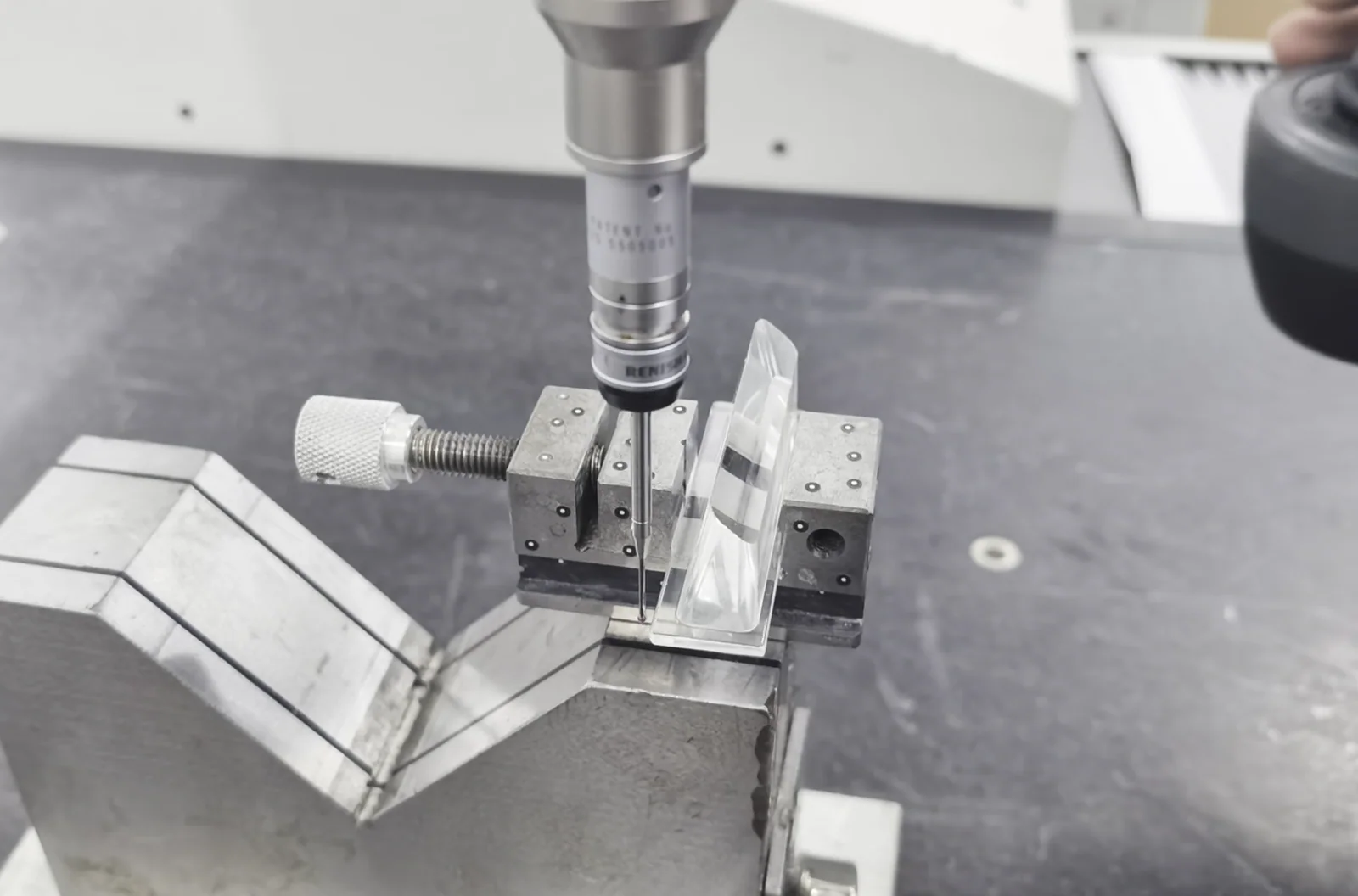
Account for measurement uncertainty when setting acceptance decisions, particularly near a tolerance boundary. Where an instrument cannot access the complete surface, document the coverage and complementary method instead of reporting partial data as complete verification.
Mould compensation
Compensation adjusts the tool surface for repeatable differences between the moulded component and its target geometry. Relevant effects can include glass contraction and relaxation, mould expansion, load-induced deformation and the coating's contribution to the glass-contact surface.
Correct machine and tooling alignment before calculating surface compensation. Base compensation on repeatable residual form error under a stable, qualified process. Unstable preform mass, changing thermal conditions or inconsistent closing position cannot be resolved reliably by modifying the optical surface.
Measure multiple components using consistent datums and analysis settings. Separate systematic surface error from sample variation, and retain cavity identity in multi-cavity work. Check that changes in fitting, aperture or removed terms have not created an apparent improvement that merely reflects a different measurement definition.
Calculate the correction, manufacture or rework the insert, then repeat coating, inspection and moulding. Keep the substrate correction and intended coated geometry traceable to each other. Coating thickness is part of the geometry budget; thickness variation across the aperture may introduce additional form error.
Do not assume that a previous correction remains valid after changing the glass, cycle, coating system or support arrangement. Record the process conditions under which the compensation was established. Release a compensation revision only after the resulting parts demonstrate acceptable performance and repeatability, not simply because the revised insert matches its machining target.
Release-coating selection and deposition
A release coating is a functional layer on the tool, not an optical coating applied to the finished lens. Its purpose is to limit glass adhesion and damaging interactions while preserving the required surface geometry and texture.
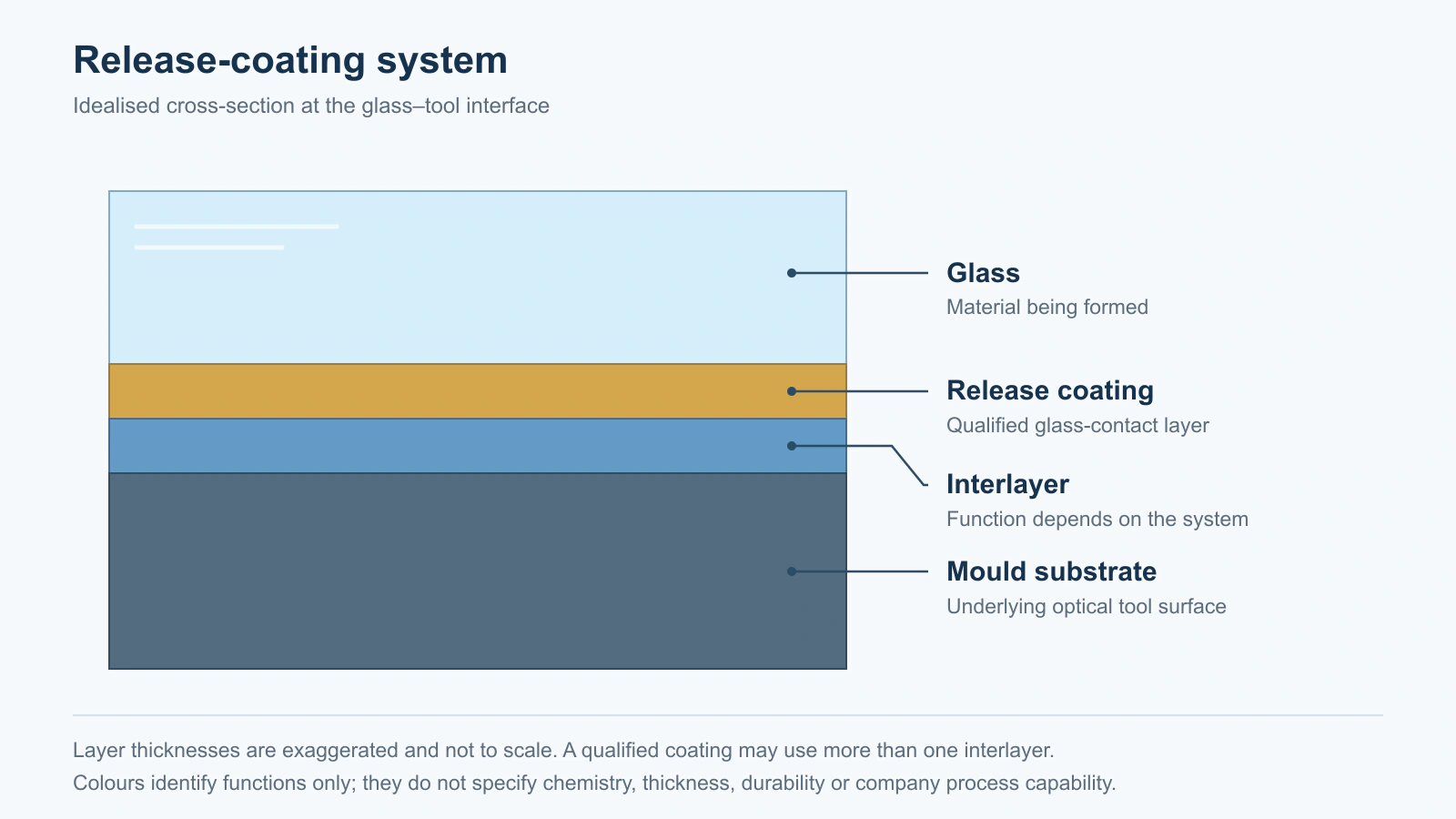
Coating systems reported in research and industrial practice include noble-metal, nitride, carbide, carbon-based and oxide systems, sometimes with multiple functional layers. Appearance in the literature does not establish suitability for the current glass, substrate, temperature or atmosphere. Qualification must address the actual combination and intended operating cycle.
The layer beneath the glass-contact surface also matters. Adhesion and diffusion-barrier layers have distinct functions, even when one layer contributes to both. Research on PtIr tooling systems compared different layer thicknesses and observed interdiffusion, oxidation, coating spallation and glass sticking. Those results support evaluating the complete layer stack; they do not establish a universal film thickness or lifetime. See the experimental study by Friedrichs and colleagues.
Release coatings may be deposited by qualified physical vapour deposition (PVD) methods, such as sputtering, or by chemical vapour deposition (CVD) where appropriate to the coating system. Control substrate preparation, deposition conditions, insert orientation, layer composition, thickness and residual stress.
Cleaning and activation must remove contamination without degrading the optical surface. Protect approved locating surfaces, and define any masking boundaries. Steep or recessed surfaces may receive different coverage from flat regions, depending on the deposition method. Verify the actual geometry instead of assuming that a flat witness coupon represents the complete insert.
Coated-tool inspection and qualification
Inspect the coated insert before moulding. Compare its form and texture with the uncoated baseline, using compatible measurement settings. Check particles, scratches, pinholes, edge coverage and coating on locating surfaces. Confirm that the method itself will not mark a sensitive layer.
Witness coupons can support composition, thickness and adhesion testing. However, coupon results do not replace inspection of the actual optical surface where curvature, shadowing or fixture orientation affects deposition. Destructive adhesion tests belong on qualified samples unless the test plan specifically permits sacrificing an insert.
Qualification should demonstrate more than one acceptable lens. Include sufficient repeated cycles to evaluate stabilisation, early coating changes and developing defects. Record finished-part form, texture, dimensions, alignment-related errors and release behaviour against the tool and process configuration.
Evaluate cavity-to-cavity variation separately. Where production includes shutdowns and restarts, include the relevant restart condition in the validation plan. A tool may behave differently during initial heating than during a repeatable production sequence.
Define the sampling frequency, acceptance criteria and response to abnormal results before testing begins. Do not select only favourable cycles for the final report. Link rejected parts and interruptions to their process records, since they can reveal limitations hidden by average yield. Complete qualification by inspecting the tool again and documenting any change from its initial coated condition.
Sticking, coating failure and cleaning
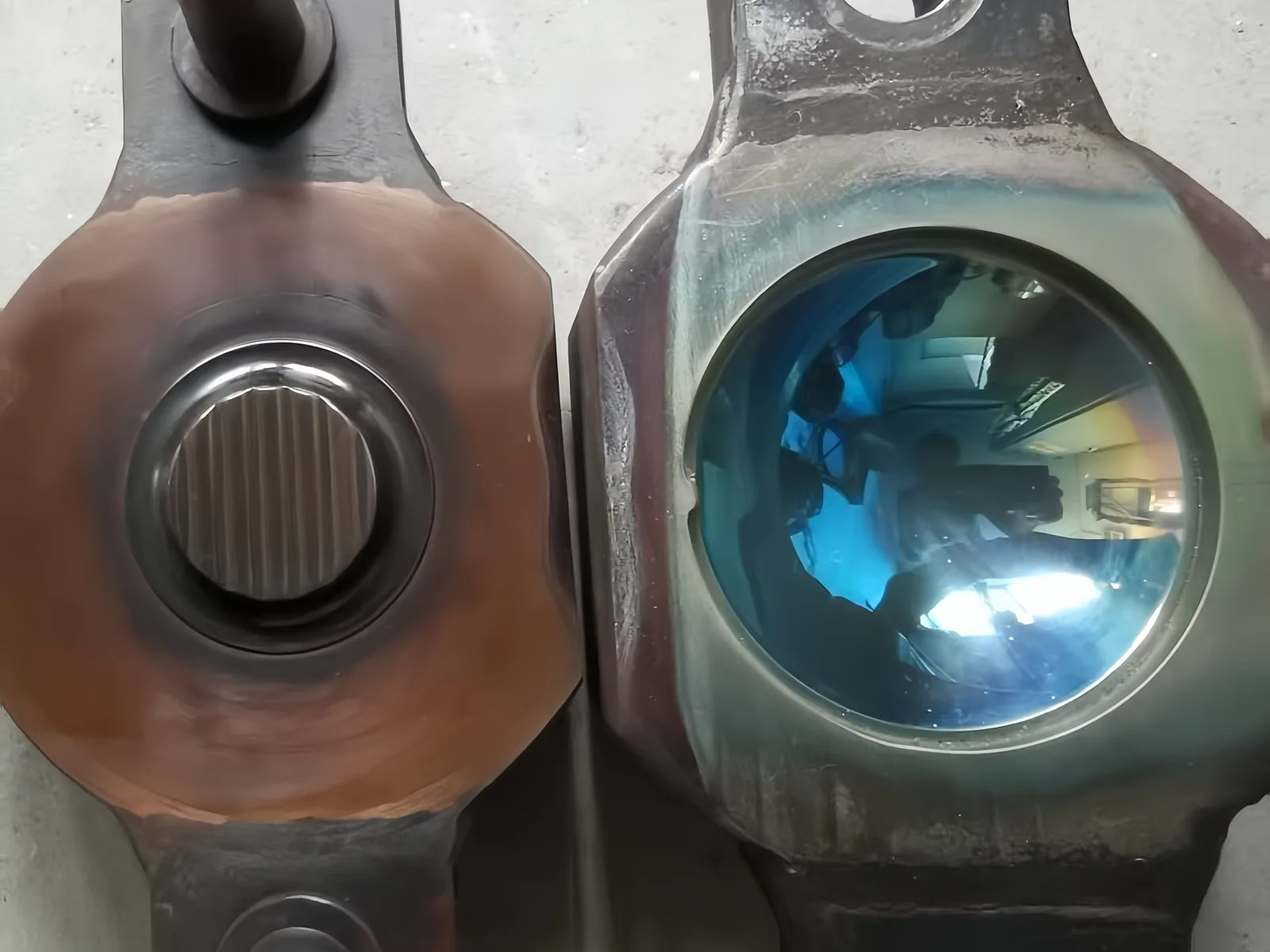
Sticking may arise from glass–coating incompatibility, excessive thermal exposure, contamination, damaged coating or an unsuitable release condition. Similar visible defects can have different causes, so diagnosis should connect part measurements, tool inspection and process history.
The table below gives investigation starting points, not one-to-one diagnoses. Preserve representative parts and record the affected cavity and surface location before intervention.
| Observed symptom | Possible causes | Evidence to check | Initial action |
|---|---|---|---|
| A repeated mark at the same location | Deposit, local coating damage or substrate defect | Corresponding tool region and successive part images | Inspect the mapped region; clean only by an approved method |
| Rising release resistance or glass transfer | Coating deterioration, contamination or changed release conditions | Tool condition, temperature history and release records | Hold production at the defined limit and investigate |
| Progressive form drift | Thermal instability, support changes or permanent tool deformation | Part and tool maps, alignment and recipe history | Check process and assembly stability before considering compensation |
| Roughness increase or flaking | Wear, reaction, oxidation or delamination | Microscopy, atmosphere records and coating history | Isolate affected tooling and assess the layer and substrate |
Stop production when defined release or surface-quality limits are exceeded; do not wait for complete sticking. Segregate potentially affected parts according to the traceability and containment plan.
Cleaning should specify approved tools and chemistry, contact restrictions, drying and return-to-service checks. Routine abrasive polishing can remove coating and alter form; treat it as rework, not ordinary cleaning. Where cleaning does not restore the approved condition, investigate before repeated intervention obscures the failure evidence.
Tool-life monitoring, recoating and replacement
Define useful life through acceptable performance, supported by cycle history. Record exposure conditions as well as cycle count: glass grade, recipe, thermal holds, atmosphere, cleaning, interruptions and maintenance can all change the meaning of an apparently identical number of cycles.
Monitor cavity-specific form, texture, defects and release behaviour against established intervention limits. Review trends early enough to contain affected production. A visual inspection alone may miss changes that are already measurable in the finished optics.
Removal-from-service and replacement criteria
Distinguish three decisions. Temporary removal allows inspection, cleaning or failure analysis. Restoration permits qualified recoating or rework when the substrate remains recoverable. Final replacement applies when cracking, irreversible damage or insufficient remaining material prevents restoration to the approved condition.
A worn release layer does not automatically mean the insert substrate has reached end of life. Before recoating, qualify the stripping method and verify that it preserves form, texture and edges. After rework or recoating, remeasure and requalify the changed tool before production use.
Keep each insert in identified, non-contact protective storage. Record issue, return and maintenance status so unqualified or damaged tools cannot be confused with released tools. Spare inserts require performance verification; a shared drawing number alone does not demonstrate interchangeability. Define whether a replacement cavity may be qualified independently or whether the matched assembly needs renewed validation.
Development workflow and change control
Use six stages to connect the tooling decisions without treating substrate, coating and process approval as separate exercises:
- Confirm inputs. Resolve the finished-component definition, glass and preform specification, equipment constraints and acceptance methods.
- Design the tooling. Establish architecture, datums, materials, operating-temperature clearances, support, filling and release strategy.
- Manufacture and measure. Produce the inserts and record baseline form, texture, dimensions and datum relationships.
- Coat and remeasure. Apply the qualified layer system, inspect the actual inserts and verify assembly compatibility.
- Trial and compensate. Establish stable moulding, inspect repeated samples and correct only repeatable residual error; repeat coating and validation after correction.
- Validate life and freeze the configuration. Evaluate repeated-cycle performance, define maintenance and intervention criteria, and release the documented tooling arrangement.
Retain a compact but complete history for each insert: identity, drawings, substrate grade, compensation revision, coating specification and batch, measurement files, qualification results and maintenance events. Preserve the connection between those records and the finished parts they produced.
Review changes to material grade, coating structure, supplier, thickness, cleaning chemistry, fits, equipment or process conditions. Define the inspection and requalification required for each change, including any agreed customer approval. A change to a tool can affect optical performance even when the component drawing remains unchanged.
Stable replication depends on preserving the relationship between geometry, alignment and release throughout the tool's service history. A controlled tool is not merely an accurate cavity: it is an identified, measured and maintained configuration whose performance has been demonstrated under its intended process conditions.
Scope note: This guide provides general engineering guidance, not guaranteed tooling capability or service life. Material suitability, tolerances, coating performance and maintenance intervals require assessment for the actual glass, geometry, equipment and inspection method.
Contact Us
Your feedback fuels our growth, and your questions drive our solutions.
We value your feedback, inquiries, and suggestions. Please feel free to get in touch with us
General inquiries
Please contact us via sales@bo-glass.com, and we will reply to you as soon as possible.
Interested to work with us
Drop your resume at info@bo-glass.com
and we will get back to you shortly.
We uses the contact information you provide to us to contact you about our relevent content, products, and services.