
Borosilicate glass material overview
Design Guidelines for Molten-Formed Borosilicate Glass Components
Start the drawing with the surfaces that matter to the assembly, the optical path and the service environment. Then show the entire glass section. A design review can use those views to assess how the molten glass moves, how the tool opens and how the finished part is measured.
Choose a Forming Route and Define the Wall Profile
Molten blowing can produce hollow bodies and domes. The exterior may be shaped by a mold while the inner surface depends on glass distribution during inflation. Direct pressing displaces a molten gob between a tool cavity and plunger, which can define opposing surfaces where both tools have access. Review the route against the finished part, including secondary operations and sample verification. BO-Glass blowing design guide · BO-Glass pressing design guide
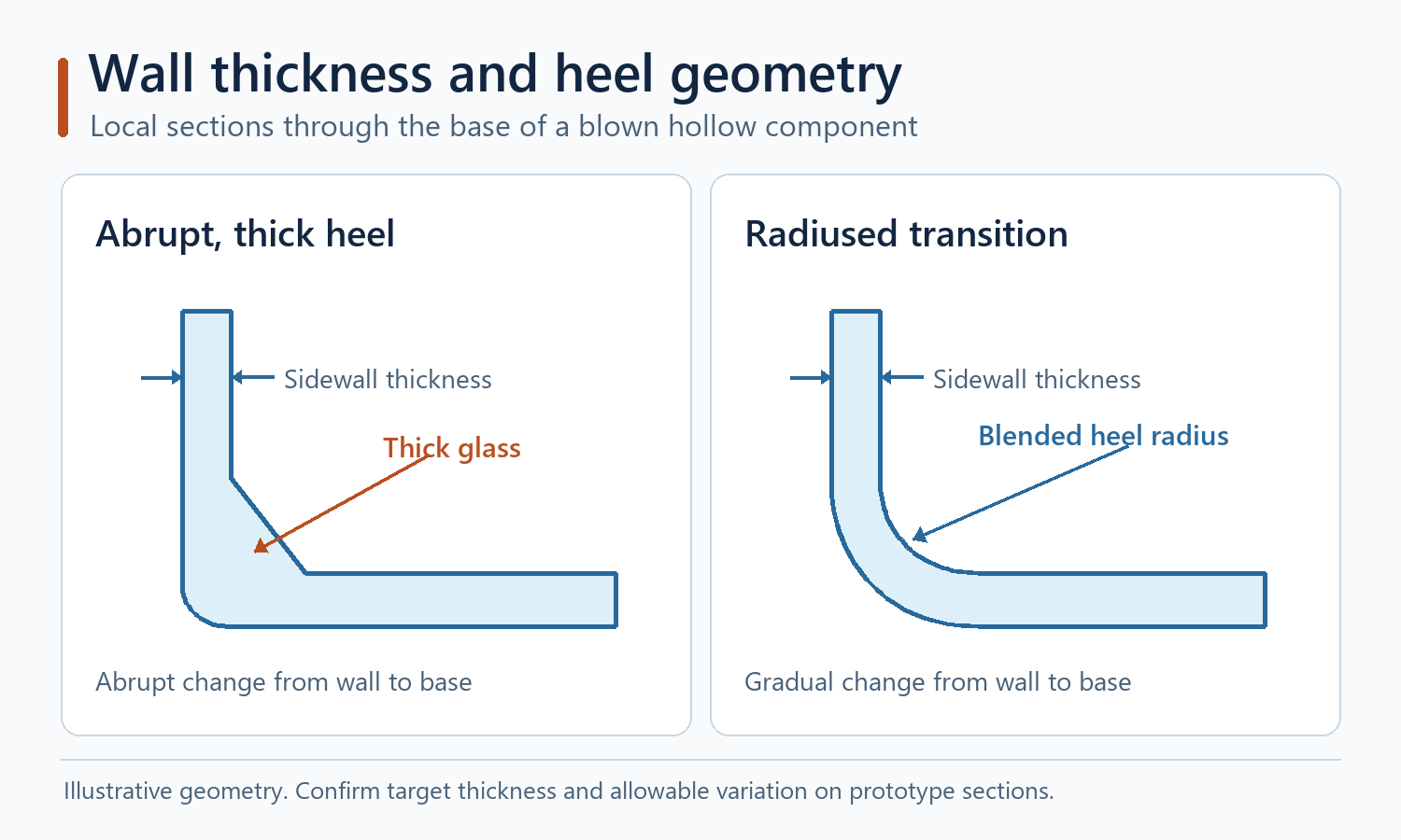
Identify minimum thickness and section changes at the rim, shoulder, sidewall, base and flange as applicable. Give critical measurement locations and directions on the drawing. A gradual transition can ease glass flow and reduce local thermal gradients or stress concentration. Review every heavy section with the annealing plan.
Review Release, Openings and Threaded Features
Indicate the preferred pressing or release direction and discuss where the parting line can sit. Check draft, internal returns, undercuts and deep recesses with the proposed tooling. Keep seams away from mating surfaces and clear optical zones where practical.
For an opening, mark the finished sealing land and specify the diameter, flatness and edge treatment required for its use. Specify any position or orientation requirement relative to the assembly datum separately. The sealing-land inspection example shows how to agree the support fixture, probe locations and acceptance method. For threads or lug features, agree the mating closure, profile, functional gauge and tooling release. Plan support or finishing where local glass thickness and edge contact become critical.
Make Dimensions and Tolerances Inspectable
Establish datums on the surfaces or axes that control fit. State the location of profile, clearance, runout or flatness requirements. Identify as-formed and finished surfaces so their requirements can be reviewed against the chosen route. Use the drawing-to-inspection checklist to confirm gauge access and measurement conditions for each critical feature. Set numeric tolerances using functional needs and representative trial-part data. BO-Glass pressing design guide
Specify the Drawing Feature and Its Check Together
| Feature | Put on the drawing or assembly brief | Agree before acceptance |
|---|---|---|
| Thin wall or heavy shoulder | Wall stations, measurement direction and profile transitions | Tool access and a thickness measurement method for each station |
| Open rim or sealing land | Datum, finished diameter, flatness and required edge treatment | Gauge or fixture and stage of measurement after finishing |
| Mold seam or release feature | Permitted location relative to optical and mating zones | Visual boundary and allowable effect on fit or viewing |
| Threaded or retained opening | Mating geometry, engaged area and intended assembly support | Functional gauge or representative hardware and fit assessment |
Validate the Mounting Interface
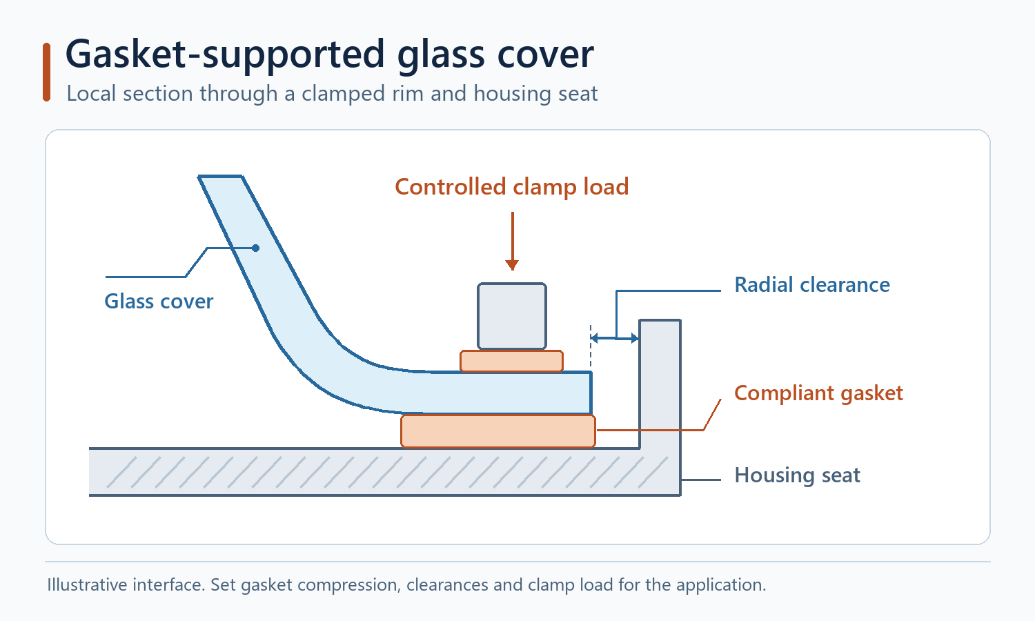
Draw the holder, gasket and retaining hardware in section. Check clearance at tolerance extremes and at service temperatures. Make the load path visible and review point contact, compression and assembly preload. For a cover exposed to rapid temperature change, test complete assemblies with the specified supports and finishes. Use the actual light source and aperture where a lens or diffuser has a defined optical task.
References and Data Scope
The manufacturing guides explain process choices and tooling considerations. Final radii, wall profile, closure details and tolerances are set for the specific material and validated with the tooling and inspection method used for the component.