
Borosilicate glass material overview
Borosilicate Glass Thermal Expansion, Thermal Shock and Temperature Limits
Low thermal expansion makes borosilicate glass worth considering for light covers near heat sources, protective windows that see washdown, and components that undergo repeated temperature changes. The temperature history of the mounted part determines how much of that material advantage it can use.
Start with the Service Conditions
Choose the exposure that matches the installed part. Include each applicable row when a component sees several conditions, such as repeated start-up followed by cold spray.
Thermal Exposures and Measurements
| In-service exposure | Reproduce in the test | Record with the result |
|---|---|---|
| Steady heat from an enclosed source | Source position, actual mount, ventilation and operating load | Which glass locations reach the highest temperature and how long they remain hot |
| Cold spray on a warm outer wall | Starting glass temperature, spray location and agreed exposure cycle | Time and location of the temperature change, cracks and post-test fit |
| Repeated start-up and shutdown | Heating and cooling rates, cycle count and the intended support | Changes in appearance, fit or function after the specified cycles |
| Glass located against a metal frame | Assembly clearance, gasket condition and the temperatures of both materials | Whether supports move or contact changes as the assembly heats |
Linear Thermal Expansion
The mean coefficient of linear thermal expansion, or CTE, describes the fractional change in length per degree over a stated temperature interval. In low-expansion borosilicate formulations, the arrangement of the silica and borate network leads to a small net change in dimensions as the structure vibrates and expands. The types of boron coordination and the balance of network formers and modifiers vary with composition. Characterize expansion for the selected grade over the relevant interval. Experimental study of boron coordination and expansion in borosilicate glass
SCHOTT publishes a mean CTE of 3.3 × 10⁻⁶ K−1 from 20 °C to 300 °C for DURAN® 3.3. Using that value for an illustrative calculation, a freely expanding 100 mm length heated uniformly across the full interval increases by about 0.092 mm. For a cover in a metal holder, calculate growth of both components at their own operating temperatures and include dimensional variation in the clearance estimate. SCHOTT DURAN® technical data
Where Thermal Shock Develops
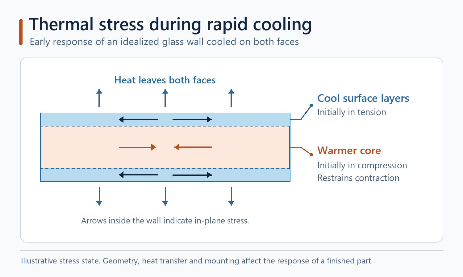
When cold water strikes a hot cover, the wetted exterior can cool and contract while the inner glass remains warmer. The warmer glass restrains that contraction, placing the cooled region in tension during the transient. During fast local heating, the hot zone tries to expand against cooler surrounding glass, and tension can develop elsewhere on the component. Look at the temperature difference and its location through the wall and across the part. A low CTE reduces the strain mismatch for a given gradient. The resulting stress also depends on geometry, stiffness, heat transfer and constraints. DWK guidance on heating laboratory glassware
Wall Thickness and Mounting
A heavy base, rim or shoulder can lag behind a thinner wall during heating or cooling. Check abrupt section changes, locations where liquid collects and areas close to emitters or metal heat sinks. Inspect the edge condition at a loaded rim, where a small chip can raise the risk of fracture. When the assembly uses a compliant gasket, define its seating surfaces, travel, compression and clearances through the expected temperature range. Include the actual support in thermal validation because the mount can change both heat flow and restraint. The mounting interface guide shows how to review clearance, compression and the load path together. BO-Glass blown glass design guide
Temperature Limits and Validation
Transformation, annealing and softening temperatures describe changes in material behavior under defined test conditions. Continuous temperature, short excursions and thermal shock are separate service requirements. Support loads, gradients, exposure duration, repeated cycling, seals and coatings can limit the finished assembly. Use material data to screen a grade and define service limits using representative parts.
For a hot lighting cover that may encounter cold spray, document the heat source, ambient range, stabilizing time, initial glass temperature, spray conditions and number of cycles. Use the final glass geometry, edge finish and mounting. Record where temperatures were measured and define acceptance for cracks, fit and any optical or sealing function. Include locations with the highest expected gradient or restraint.
References and Data Scope
The calculation above illustrates free expansion for a named reference grade. A finished-part thermal specification should identify the approved grade, mounting, heat transfer conditions, test sequence and pass criteria.