
Borosilicate glass material overview
Borosilicate Glass Specifications, Inspection and Quality Control
The drawing, material specification and inspection plan establish what is supplied and how acceptance is decided. Agree them together so a compliant part also fits the assembly and performs under its intended conditions.
Identify the Material, Revision and Supplied Condition
Record the part number, drawing revision, relevant standards and approved glass grade or formulation identifier. Verify the incoming material or controlled batch identity against that requirement. Agree the evidence required for approval, such as formulation records or a material declaration, and define the finished condition, including annealing, edge work, frosting, print or coating. Use traceable sample identification to link inspection records to the relevant production lot.
Translate Drawing Requirements into Checks
| Characteristic | Define before inspection |
|---|---|
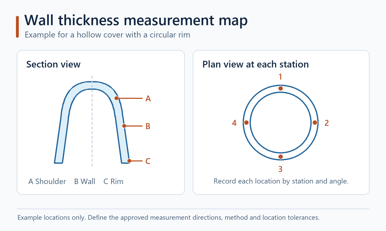
| Wall and base thickness | Measurement locations, direction and a verified method for the curved geometry. Include inaccessible locations in the method review. |
| Dimensions and fit | Datums, fixture or functional gauge, measurement stage and which dimensions apply after edge finishing. |
| Finished sealing-land flatness | Mark the land on the drawing and agree the support, probing coverage and acceptance method. |
| Internal and surface appearance | Critical zones, feature definitions, size and quantity criteria, inspection lighting and borderline samples. |
| Residual stress | Method, location, orientation, optical path and the stated acceptance metric. |
| Optical performance | Wavelength range or light source, test geometry, aperture and endpoint such as spectral transmission, haze, beam distribution or distortion. |
| Functional performance | Actual assembly or representative fixture, service conditions, test sequence and pass criteria. |
Use a wall map instead of a single reading where thickness varies. A formed optical cover might need readings through the shoulder, along the sidewall and at the rim. Validate any non-destructive thickness method against an independent reference, especially where curvature or surface finish affects the measurement. BO-Glass annealing and quality inspection guide
Select a Wall Thickness Measurement Method
| Method | Where it can help | Setup to verify |
|---|---|---|
| Contact thickness gauge | Both faces are accessible at the stated location | Confirm tip access, contact force and measurement direction on the curved wall. |
| Ultrasonic thickness gauge | Only one face is accessible and the glass and geometry give a usable signal | Validate against known thicknesses of the same glass and check coupling and probe alignment at the actual curvature. |
| Sectioned trial sample | An inaccessible feature needs a direct cross-sectional reference | Locate the cut on the wall map and measure the prepared section in the specified direction. |
Evident ultrasonic thickness measurement guidance

Example Check for a Finished Sealing Land
Identify the actual gasket-contact area on the drawing. Support the finished part in a stable inspection fixture that keeps the land accessible and avoids distorting it. Agree where a probe will sample the land, how those measurements will be evaluated and the finished state to be inspected. Record the result against the drawing limit. Flatness describes the form of the sealing land itself. If the land must also be parallel to the mounting face, specify and inspect that orientation against the stated datum. ASME fundamentals of geometric tolerancing
Assess Residual Stress and Function Separately
A qualified polariscopic method assesses stress-related optical retardation. The setup and interpretation depend on thickness, geometry and composition. ASTM C148 describes procedures for commercial soda-lime-silica glass containers. For a borosilicate component, validate the method and acceptance value for the actual part and check its final thermal condition. For a light cover exposed to heat and moisture, an application test can use the actual lamp, mounting arrangement and agreed thermal cycle. A stress reading and a functional result answer different questions. ASTM C148
Separate Qualification, Lot Acceptance and Change Control
Qualify representative trial parts from the intended process. Agree which tests are repeated on each lot, which rely on agreed sampling and which are reserved for qualification or requalification. Define lot boundaries, report contents, disposition of failed lots and the treatment of out-of-limit measurements. Document which changes, such as a glass formulation, forming tool or finishing sequence, call for renewed review and retesting.
References and Data Scope
Use the manufacturing guide and standard above to select applicable checks. Reference material data, sample results and production acceptance criteria represent different evidence. Identify each clearly in the drawing and inspection plan.