
Borosilicate glass material overview
Optical Properties and Spectral Transmission of Borosilicate Glass
A lighting shade, a lens and a protective cover can all use clear borosilicate while requiring different optical results. Specify where the light passes, which wavelengths matter and whether the intended function is transmission, imaging or diffusion.
Read a Spectral Transmission Curve
Spectral transmittance is the fraction of incident light transmitted at each wavelength under specified conditions. Use data for the approved glass and a stated path length, surface finish and measurement geometry. Check the short-wavelength edge when UV or violet light matters. For a visible-light application, specify the relevant wavelength band or the source and weighting used for a single transmittance value. Keep normal-incidence data distinct from measurements at the angle used by the assembly. SCHOTT TIE-35 on transmittance of optical glass
Choose Optical Checks by Component Function
| Component function | Candidate acceptance checks | Include in the setup description |
|---|---|---|
| Diffusing lamp shade | Beam spread, lit uniformity and visible source hot spots | Lamp or LED, its spacing to the shade, and the viewing or collection angles |
| Beam-shaping lens | Beam pattern and intensity at specified locations | Source position, installed orientation and measurement distance |
| Clear viewing cover | Spectral transmission, haze or image distortion as required | Clear aperture, actual viewing direction and optical path thickness |
| Color-matched lighting cover | Transmitted or reflected color under agreed illumination | Sample thickness, finish, illumination and approved comparator |
Refractive Index and Surface Reflection
External transmittance includes surface reflection as well as losses within the specimen. Internal transmittance accounts for the passage through the glass after correcting for surface reflection in the stated setup. For illustration, the DURAN® 3.3 reference index of 1.473 at 587.6 nm gives approximately 3.7% Fresnel reflection at one ideal uncoated air-to-glass interface at normal incidence. A finished part has multiple optical surfaces, and angle, coating or contact with another medium can change the result. SCHOTT DURAN® technical data · SCHOTT TIE-35 on surface and internal losses
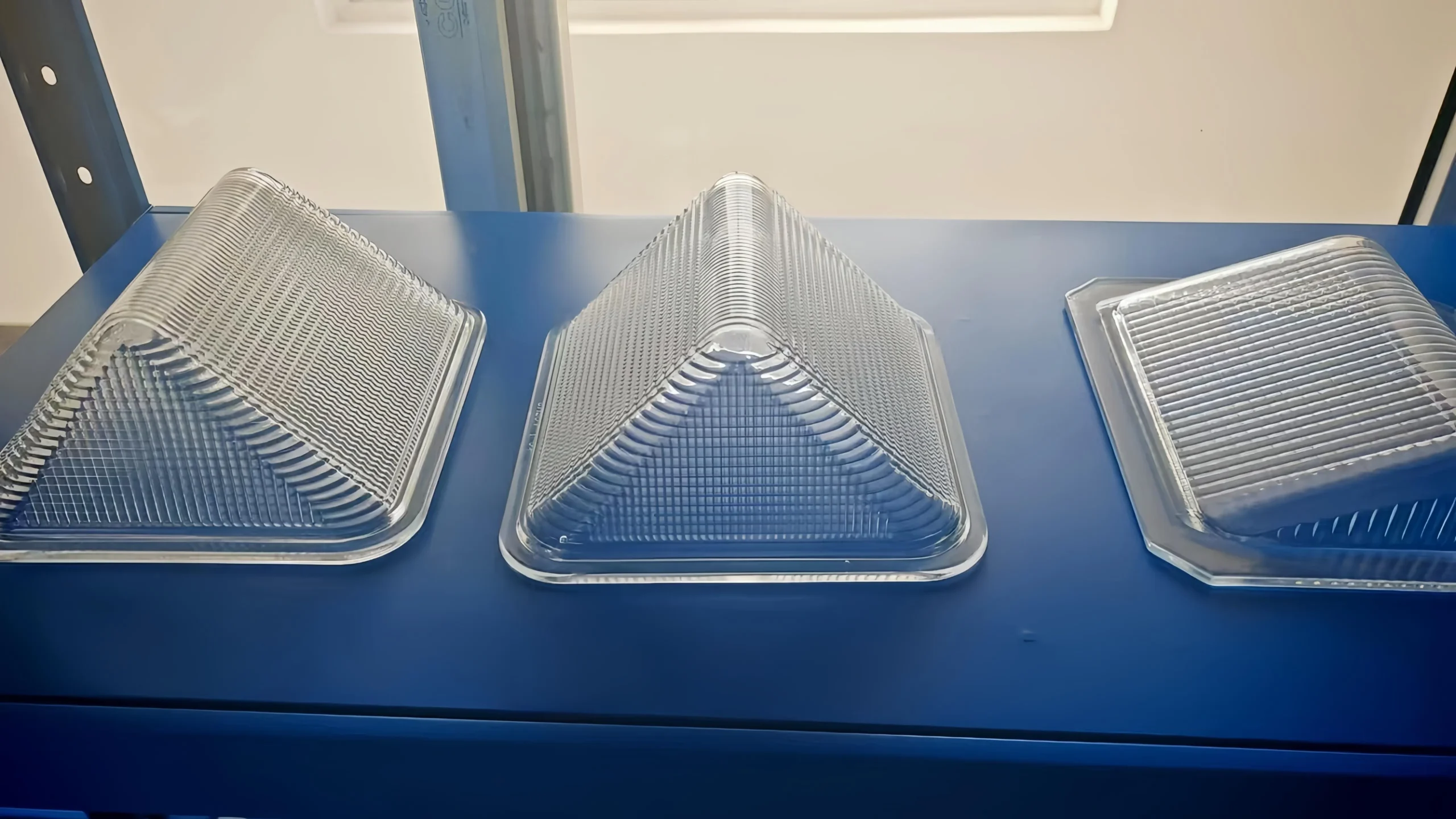
Curvature, thickness variation and the change of refractive index with wavelength affect how a lens directs rays. For a viewing cover, even clear glass can shift or distort the image. Check the clear aperture at its actual viewing angles and distance. Add a beam or imaging test when features such as focus, uniformity or distortion control acceptance.
Thickness, Color and Internal Quality
At wavelengths where the glass absorbs, a longer glass path typically passes less light. A thick section can therefore look darker or show a stronger tint than a thin section from the same melt. For colored glass, compare approved samples at representative thickness and under the intended light source. Use transmitted light to evaluate bubbles and striae. Bubbles can scatter or redirect light, while striae can locally bend rays through refractive-index variation. Specify the inspection zone and the tolerated effect on the final view or beam. SCHOTT TIE-35 on absorption and thickness · SCHOTT TIE-25 on striae
Diffusion, Frosting and Coatings
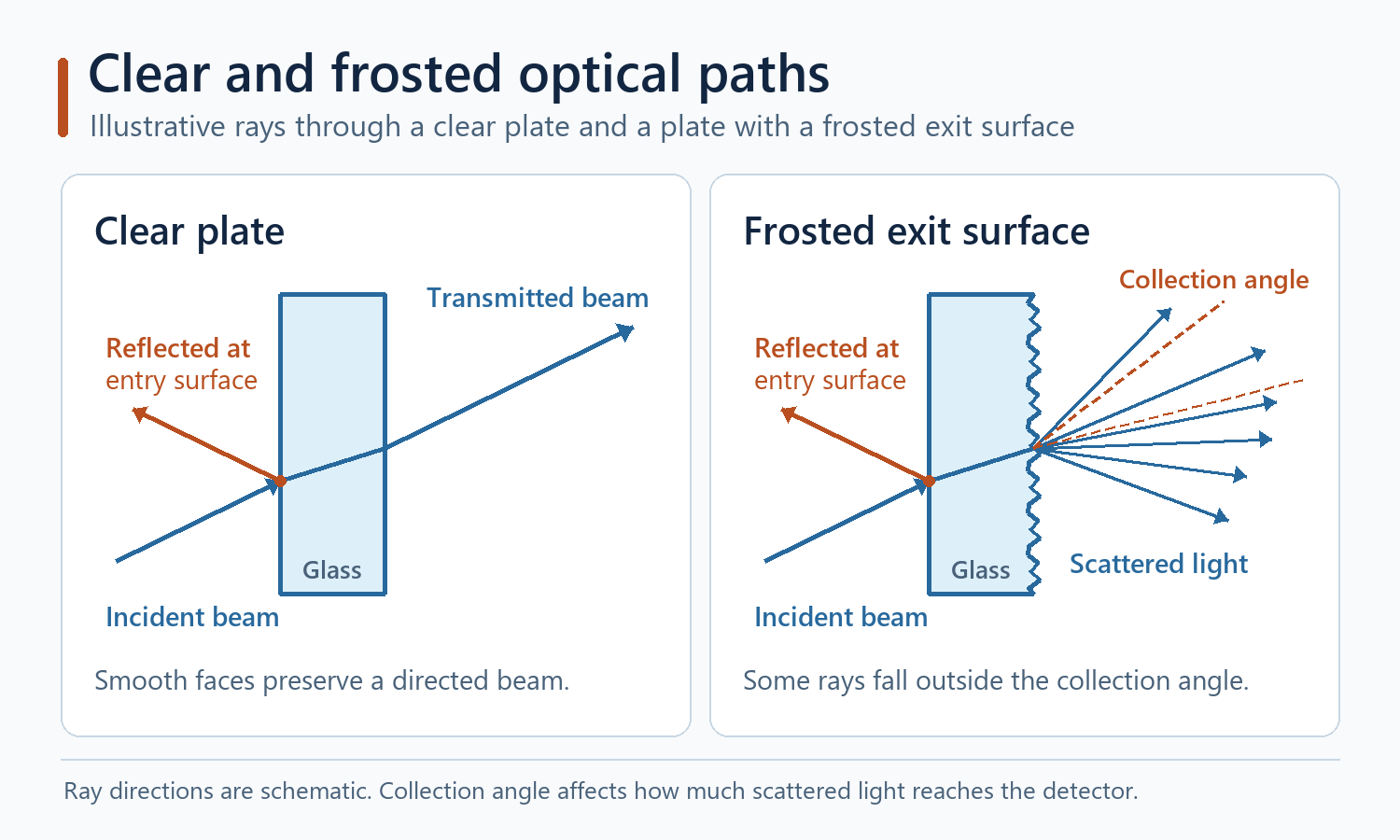
Frosting redirects light over a wider range of angles. A measurement that collects a narrow forward beam can give a different result from one that collects diffuse light over a wide angle. Select the method for the function. A shade may call for a beam distribution and visual evaluation of source hot spots. A protective cover may call for retained visibility, low haze or a limit on reflected glare. Test with the agreed surface finish and coating. BO-Glass sandblasting and frosting · BO-Glass coating guide
Compare Clear and Frosted Finishes Under Controlled Conditions
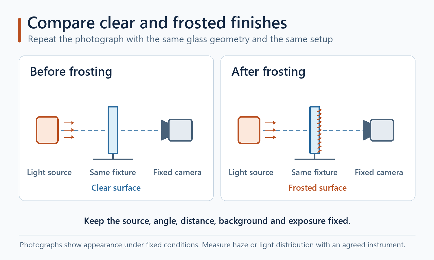
Use the same borosilicate part before and after frosting when practical. If two specimens are needed, match the part number, glass grade, wall thickness in the viewing zone and all other finishes. Keep the fixture and exposure settings fixed so the pair records the effect of the finish under those viewing conditions.
| Control | Keep fixed or record |
|---|---|
| Specimen and treated face | Same part before and after, or matched specimens. Record the thickness at the observed area and the face being frosted. |
| Illumination and part position | Same source and output, source distance, glass orientation, aperture and background. |
| Image capture | Same camera position and angle, lens, manual exposure and white balance. Record the diffuse appearance and the visibility of any source hot spot. |
| Quantitative result | Use the agreed instrument and collection geometry for total transmittance, angular light distribution or haze where appropriate. Record the result separately from the photographs. |
References and Data Scope
Report the material, wavelength band, wall or optical path length, aperture, orientation, incident angle and collected light. Add the fixture and light source where beam performance is specified. The optical examples above are reference mechanisms and calculations. Acceptance values belong to the finished design and its test method.