
BO-GLASS / TECHNICAL MATERIALS
Specifying and Inspecting Custom Soda-Lime Glass Components
A glass specification becomes useful when it connects each important requirement to a defined feature, a verification method and an acceptance decision. A drawing can describe the outside shape while leaving uncertainty about wall distribution, appearance, seating, residual stress or service performance.
This guide explains how to prepare a practical inspection brief for blown, pressed and fabricated soda-lime glass components. Use it to distinguish material references, dimensional results, visual approval and finished-product validation. For the material context, see our soda-lime glass overview.
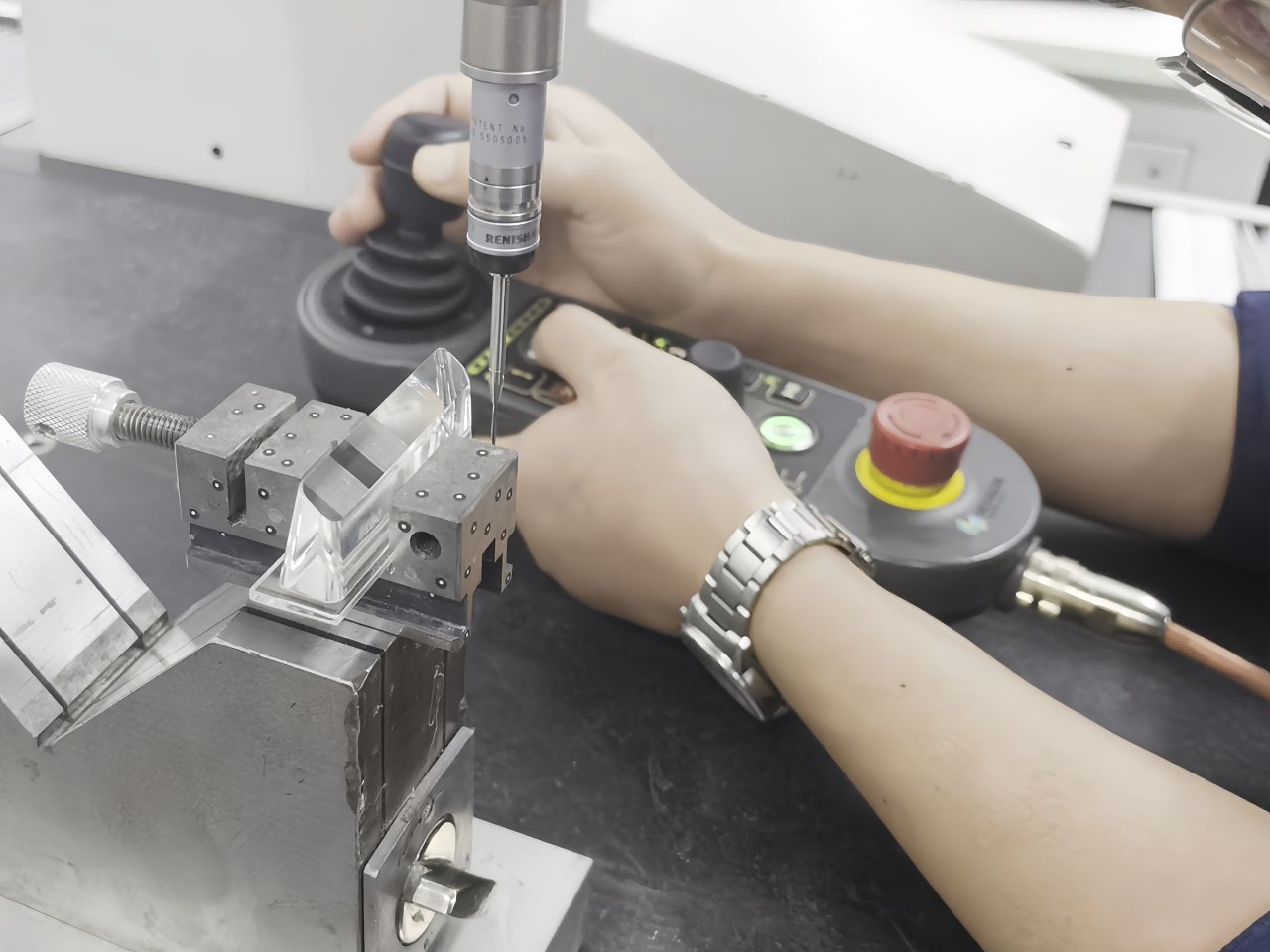
Control the Drawing, Material Description and Acceptance Basis
Identify the part number, drawing revision, units and referenced specifications. Describe the material and relevant processing condition, including forming, finishing and any strengthening treatment. A trade name or “clear glass” description alone does not establish every required characteristic.
Separate design targets from acceptance limits. A nominal wall or outside diameter communicates intent; the permitted variation, relevant location and measurement definition determine what can be accepted.
State which document controls each characteristic when a drawing, purchase order and sample differ. For example, the drawing may control a seating diameter while an identified reference establishes color and texture. Passing the visual comparison does not override a failed functional dimension.
A retained sample needs identification, revision or approval date and a clear statement of what it represents. Photographs help communicate a concept, but perspective, lighting and display settings make them unsuitable as the sole dimensional or color reference.
Build an inspection matrix before tooling or production. Record the characteristic, location, limit or reference, method, sampling and result required. These fields define the agreed inspection scope; they are not a default BO-GLASS test package.
For the relationship between geometry, manufacturing and verification, see the blown and pressed soda-lime glass design guide.
Define the Dimension, Datum and Measurement Setup
Both parties need to evaluate the same quantity at the same location. A formed cover can have different diameters at its rim, shoulder and body. One caliper reading does not describe its complete profile, roundness or alignment.
Identify the functional references. A seating feature can establish an axial reference; a locating feature may establish position or an axis. Mark the measurement section and directions rather than relying on an inspector to choose them.
Play animationClose animationReferences and measurement section
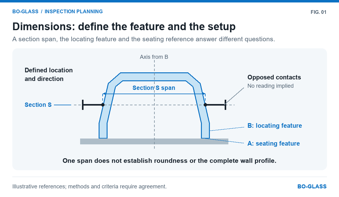
A fixture should represent the required support without changing the feature being assessed. Contact force, rocking on an irregular rim, access to the inner surface and local texture can affect results. Define the measurand and setup before selecting an instrument.
Contact measurements, optical measurements and functional gauges can answer different questions. A gauge representing a mating base can test an assembly relationship, while measured dimensions help identify why it fails. State when either or both are required, including control of the gauge and its use.
NPL’s coordinate-measurement guide explains task-specific measurement uncertainty. A machine’s advertised performance or display resolution does not establish the uncertainty of every glass-component measurement.
Results near a tolerance boundary
ISO 14253-1:2017 addresses conformity decisions for dimensional specifications with measurement uncertainty considered. Agree the decision rule instead of assuming that a displayed reading inside the limits resolves every case.
Illustrative example, not a BO-GLASS tolerance or capability: a drawing specifies 50.00 ± 0.10 mm. A result of 50.09 mm is reported with expanded uncertainty 0.03 mm. The corresponding interval is 50.06–50.12 mm, crossing the upper limit of 50.10 mm.
Under a rule requiring that interval to remain within the specification limits, this result does not demonstrate acceptance. The crossing alone does not prove that the part’s dimension is outside specification. Follow the agreed procedure and report the uncertainty basis and coverage factor. NIST TN 1297 provides background on measurement terminology.
Specify Wall-Profile Locations and the Meaning of Thickness
A nominal thickness can conceal a thinner shoulder, a heavy base or a local change near the opening. Decide whether the requirement concerns a target, an average, a minimum at specified locations or another defined profile.
Show the relevant sections and inspection positions on the drawing. Identify whether the method measures locally normal wall thickness or another distance between surfaces. On curved walls, those distances need not be interchangeable.
Do not assume that a few accessible points establish the minimum everywhere. When local minima affect function, review how the inspection can address the relevant region and what coverage is required.
Also distinguish direct measurement from an estimate derived from two other dimensions. A calculated wall value can depend on alignment, local shape and the uncertainty of both measurements. A suitable technique must work with the actual material, finish and access.
Wall thickness also influences mass, heat transfer and optical path. The inspection requirement should follow the feature’s function rather than an arbitrary list of equally spaced points. Keep the design and measurement locations consistent when the geometry is revised.
Define Appearance by Zone and Viewing Conditions
“High quality,” “no obvious defects” and “match the picture” leave important decisions unresolved. Visual acceptance needs a defined inspection area, illumination, background, viewing distance, orientation and any magnification.
Separate visible, optical, hidden and contact regions. An acceptable mark on a hidden body surface may need different consideration on a sealing track or in a clear viewing area. Mark zone boundaries so that an inspector can identify which criterion applies.
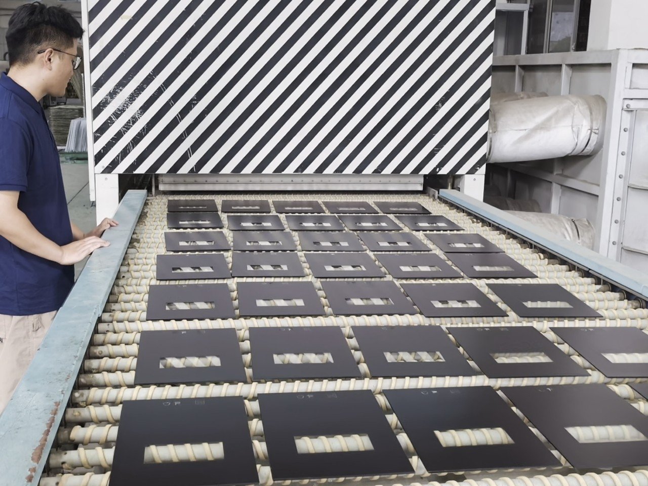
Classify the features to be evaluated: scratches, chips, inclusions, bubbles, mold seams, texture, staining and color variation. Where relevant, define how size, count, location and clustering affect the decision. Boundary samples can help communicate a permitted range when their identity and interpretation are controlled.
Keep appearance and function distinguishable. A visually small edge defect may affect seating or load transfer; an intentional texture is not automatically a defect. A smooth-looking sample does not establish transmission or residual-stress requirements.
Play animationClose animationAppearance zones and viewing conditions
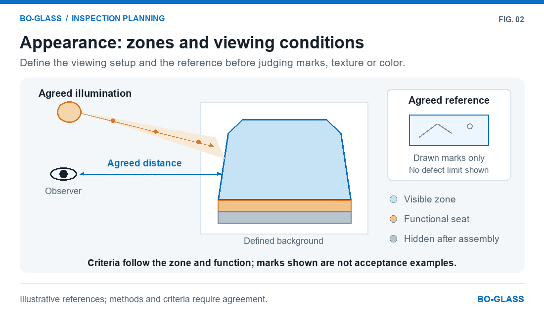
ISO 10110-7:2017 addresses surface-imperfection specification for optical elements and assemblies. Select it deliberately where relevant rather than applying a precision-optical designation automatically to a decorative shade. Likewise, ASTM C1036-25 concerns flat glass; it does not supply a default appearance grade for every blown or pressed shape.
If a standard is adopted, identify the edition, applicable scope and complete project requirements. A standard number alone does not settle inspection conditions or every acceptance limit.
Inspect Edges, Rims, Threads and Functional Fit
Edges and interfaces deserve their own inspection criteria. Identify exposed edges, handled surfaces, locating diameters, seating annuli, thread profiles and gasket contacts. Record the required finished condition and how conformity is assessed.

An edge can look polished while having the wrong profile or insufficient contact width. A rim can meet an overall height dimension while seating unevenly. Size, form, surface condition and assembly response answer different questions.
For a threaded cover, define the relevant mating profile or controlled gauge, engagement, seating position and assembly procedure. Review gasket identity and compression requirements where sealing is involved. “Screws on” is not a complete sealing criterion.
The published BO-GLASS threaded-cover case describes fit checks using the customer’s actual metal base and subsequent sealing checks. The useful lesson is to include the real interfaces; it does not establish a universal inspection frequency, protection rating or test procedure.
Protect critical features during handling and packaging. If damage appears after transport, preserve the lot identity and observations before deciding whether sorting, reinspection or another disposition is appropriate.
Assess Residual Stress With an Applicable Method
Polarized-light examination can reveal optical effects associated with stress. Under suitable conditions, stress-induced birefringence changes the light transmitted through a specimen between polarizing elements.
SCHOTT TIE-27 explains the relationship between stress, optical response and path length in optical glass. Its numerical grades are not adopted here as soda-lime component limits.
Play animationClose animationPolarized-light assessment and its limits
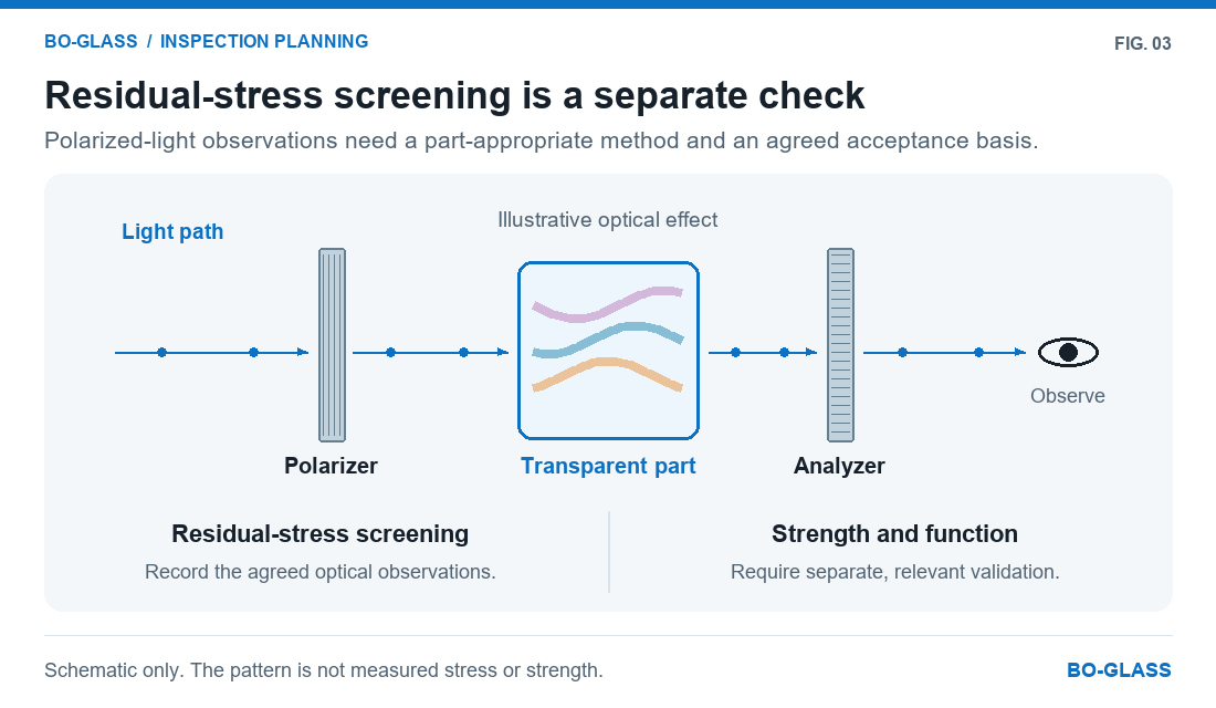
A visible pattern is not a universal numerical stress report. Interpretation depends on the material response, path length, geometry, orientation, illumination and equipment configuration. A curved or thick region cannot simply be compared with a different flat specimen by judging which looks more colorful.
Colored, opal, coated or strongly scattering parts also need an assessment of whether sufficient useful light reaches the observer or detector. Poor visibility must not be interpreted as proof of low stress. Define a suitable method and its limitations for the actual construction.
ASTM C148-17(2022) describes polariscopic examination associated with the annealing state of glass containers. Its published scope and guidance concern commercial soda-lime-silica container compositions, while discussing quality-control use for other products of similar composition. Applying it to a custom cover still requires review of geometry, optical path, interpretation and acceptance criteria.
Decide whether the requirement calls for qualitative screening, comparison with references or a quantitative measurement. Record the examination region and conditions. A satisfactory annealing assessment does not prove load capacity, impact resistance or thermal-shock performance.
Manufacturing details belong in the annealing and finishing guide; acceptance should address the specified result rather than inventing a universal cooling cycle.
Verify Optical and Functional Performance at the Right Level
Optical, thermal, sealing and mechanical requirements need methods appropriate to their intended function. Passing one category does not establish the others.
| Requirement | Conditions to specify | What the result establishes |
|---|---|---|
| Optical transmission or diffusion | Quantity, wavelength or visual weighting, specimen, zones and collection geometry. | The stated optical result under the defined method. |
| Thermal duty | Glass temperatures, rate of change, dwell, cycles, mounting and loads. | Performance through the agreed thermal sequence. |
| Assembly sealing | Base and gasket revisions, installation condition, exposure, duration and detection criterion. | The defined assembly’s response to that test. |
| Pressure or mechanical loading | Geometry, supports, load direction, duration, environment and failure criterion. | Performance within the agreed design and test basis. |
These are planning categories, not included test services or product ratings. Select the applicable procedure, laboratory or equipment, specimen quantities and decision criteria for the project.
A component check, an assembly leak check and a complete-product test under a named standard should be identified separately. Do not infer an enclosure protection rating from an undocumented water test.
Similarly, pressure suitability requires a specific engineering basis; an annealing observation or dimensional report is insufficient. Identify any destructive test and agree specimen disposition.
For optical quantities and curved-specimen issues, see the optical transmission guide. For temperature distributions and representative cycles, use the thermal behavior guide.
Separate Qualification From Routine Lot Acceptance
Qualification evaluates whether the proposed material, geometry, process and assembly can meet the agreed requirements. Routine inspection evaluates defined characteristics in subsequent production. The scopes can differ while remaining connected.
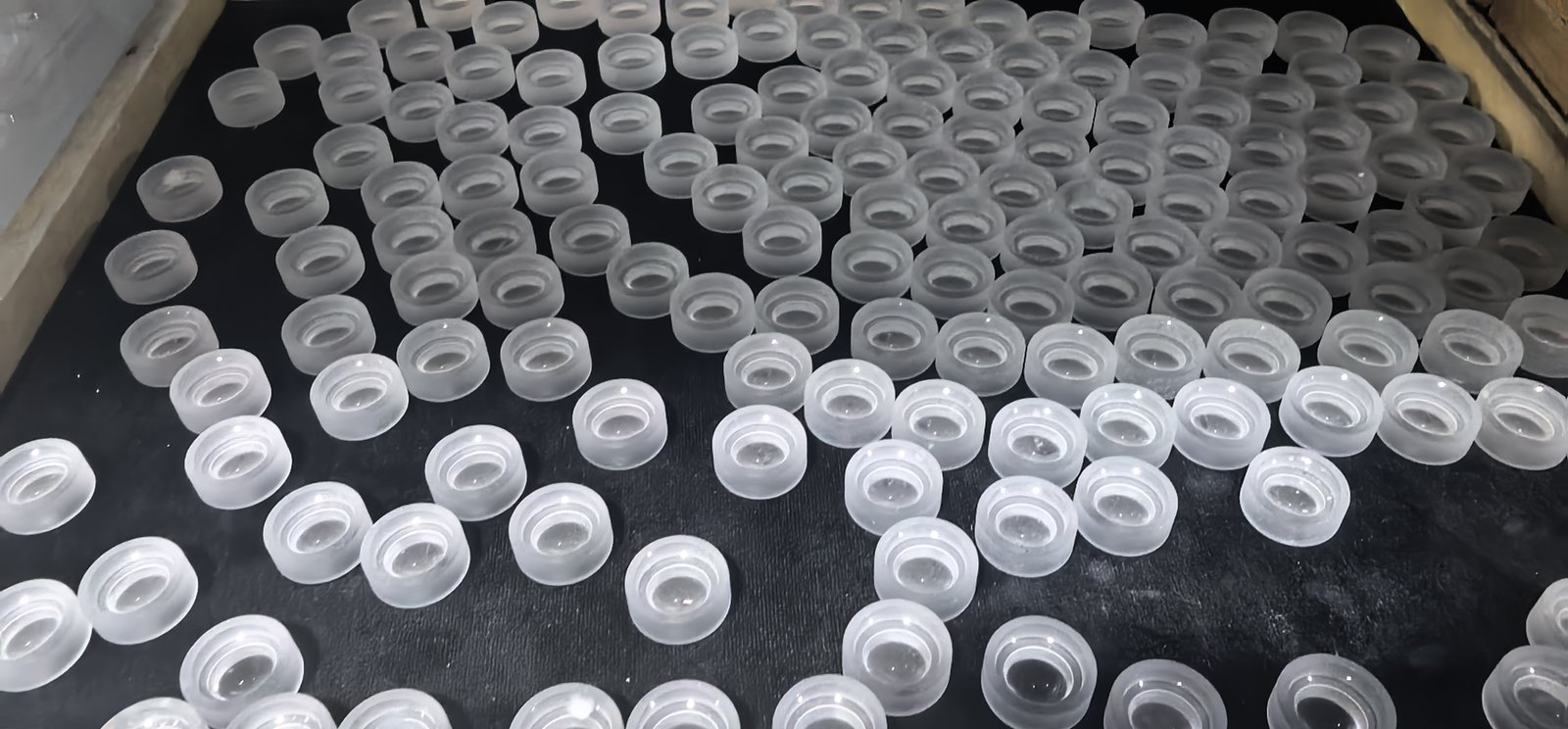
A new cover might require a broad sample evaluation of dimensions, appearance, fit and representative operating conditions. Production acceptance might then use selected dimensional, visual and functional checks. The actual plan follows the application and evidence, not an assumption that every qualification test must be repeated on every part.
Record what the approved samples establish and retain the corresponding drawing, finish and inspection revisions. One favorable sample does not characterize variation across future batches.
Revisit qualification when a relevant material, wall profile, tooling, finishing process, mating part or service requirement changes. Evaluate the effect of the change rather than automatically repeating every test or assuming that none needs review.
Keep qualification samples and routine lots identifiable. This allows an investigation to distinguish a design change from production variation or handling damage.
Agree Sampling, Acceptance Criteria and Lot Decisions
Define the lot, characteristic, selection method, sample quantity and acceptance/rejection rule before inspection. State which checks apply to all items, sampled items or qualification specimens.
ISO 2859-1:2026 provides AQL-indexed acceptance-sampling schemes by attributes for lot-by-lot inspection. An AQL number alone is not a complete plan. When adopting the standard, identify the edition, applicable scheme and level, defect classifications, relevant switching rules and the associated decision process.
Sampling does not prove that every item conforms. An acceptance number of zero also does not establish a defect-free process. An all-item check still depends on the method’s suitability and ability to detect the characteristic.
For a small isolated order, choose an appropriate approach instead of assigning a continuing-lot scheme without reviewing its applicability. For destructive tests, agree the number and origin of specimens, replacement arrangements and disposition.
Illustrative acceptance-criteria structure
| Characteristic | Requirement must identify | Decision must identify |
|---|---|---|
| Seating dimension | Drawing feature, location, datum relationship and limits. | Method, uncertainty treatment and conformity rule. |
| Wall profile | Inspection locations and the type of thickness requirement. | Coverage, limits and handling of an unresolved region. |
| Visible zone | Defect definition, viewing conditions and approved reference. | Permitted size/location/count or other complete criteria. |
| Residual stress | Applicable method, region and reference or numerical basis. | Defined interpretation and acceptance criterion. |
| Fit or sealing | Mating components, installation and functional test conditions. | Observable result and pass/fail criterion. |
This is a specification format, not a set of accepted production limits. Complete the referenced values and procedures before release. Do not attach a standard’s name to an arbitrary sample size or invent a default acceptance level for every glass product.
Keep Traceability, Reports and Changes Under Control
Agree the level of identification needed: part number and drawing revision, production lot, material or process batch where relevant, and the samples represented by each report. Serial identification of every component is not always necessary, but the supplied evidence must be connected to the correct population.
A useful report identifies the requirement, method, specimen or lot, result, decision rule and inspection date. Specify whether individual readings, summaries, photographs, material documents or functional-test records are required. A generic “passed” statement may not provide the evidence needed for a critical feature.
For nonconforming findings, identify and control the affected material. Agree investigation, reinspection, sorting or other disposition before release. Repeating a test until it passes without a justified procedure does not resolve the original observation.
Control changes to drawings, reference samples, gauges and inspection procedures as well as the product itself. A new finish, gasket or measurement fixture can change the meaning of a previously approved result.
What to include in an inspection brief
Send the drawing and revision, quantity, material and finish requirements, critical interfaces, appearance references and service conditions. Identify the inspection records needed and any characteristic that still lacks a practical method or limit.
Can a reference sample replace the drawing?
It can establish selected characteristics when its scope is recorded. Dimensions, inspection locations and functional requirements still need definitions that remain usable when the sample ages or is unavailable.
Does a dimensional report establish suitability for service?
It establishes the reported dimensional results under the stated method. Suitability also depends on material condition, surfaces, mounting and the functional validation required for the application.
Are all the checks described here included automatically?
No. Inspection scope, sampling, acceptance criteria and supplied records are confirmed in the project specification and quotation.
Prepare Your Glass Inspection Brief
Share your drawing, intended use and expected quantity. Mark the features and surfaces that control fit, appearance or optical function, and include the mating hardware or relevant drawings.
Attach your existing inspection plan if available. Tell us which requirements are fixed and which still need a suitable method, reference or acceptance criterion. This helps connect the manufacturing proposal with the evidence needed for approval.
References and Scope
Sources checked on 17 November 2026. The following references identify relevant principles and standard scopes. This guide does not reproduce their complete procedures, adopt every provision automatically or establish a certification claim.
- NPL — Coordinate-Measuring Machine Task-Specific Measurement Uncertainties, GPG130: uncertainty for coordinate-measurement tasks.
- ISO 14253-1:2017 — Decision Rules for Verifying Conformity or Nonconformity With Specifications: dimensional decisions considering uncertainty.
- NIST — TN 1297, Appendix D1: Terminology: measurement terminology and interpretation.
- ISO 10110-7:2017 — Surface Imperfections: specification of optical-element and assembly surface imperfections.
- ASTM C1036-25 — Standard Specification for Flat Glass: flat-glass scope, not a default shaped-component appearance grade.
- SCHOTT — TIE-27: Stress in Optical Glass: stress birefringence, material response and optical path.
- ASTM C148-17(2022) — Polariscopic Examination of Glass Containers: annealing-state examination in its stated scope.
- ISO 2859-1:2026 — Acceptance Sampling by Attributes: AQL-indexed lot-by-lot schemes, subject to the complete agreed requirements.
Contact Us
Discuss Your Custom Glass Project
Share your drawing, photos or dimensions, together with the intended use and target quantity. We will review your requirements and discuss the next steps.
Sales Enquiries
Email sales@bo-glass.com with your part description, intended use and target quantity.
Send Your Design
Use the form to upload a drawing or describe an existing part. Mark critical dimensions and tell us which surfaces or features matter most.
Request a Custom Glass Quote
Upload a drawing or share dimensions, quantity, intended use and finish. Include any heat, pressure or chemical exposure.
Your drawings remain confidential.
We use the contact details you provide to respond to your enquiry. See our Privacy Policy for more information.