
BO-GLASS / TECHNICAL MATERIALS
Design Guidelines for Blown and Pressed Soda-Lime Glass Parts
A useful glass design connects the outside shape with the wall profile, tooling access, finished edges and assembly. A component can look simple in a model while leaving an inaccessible recess, an uncontrolled inner clearance or a highly loaded rim unresolved.
This guide explains those relationships for custom soda-lime glass shades, covers and similar formed parts. It helps turn a design concept into requirements that can be reviewed, manufactured and inspected. For composition and material selection, start with the soda-lime glass overview.
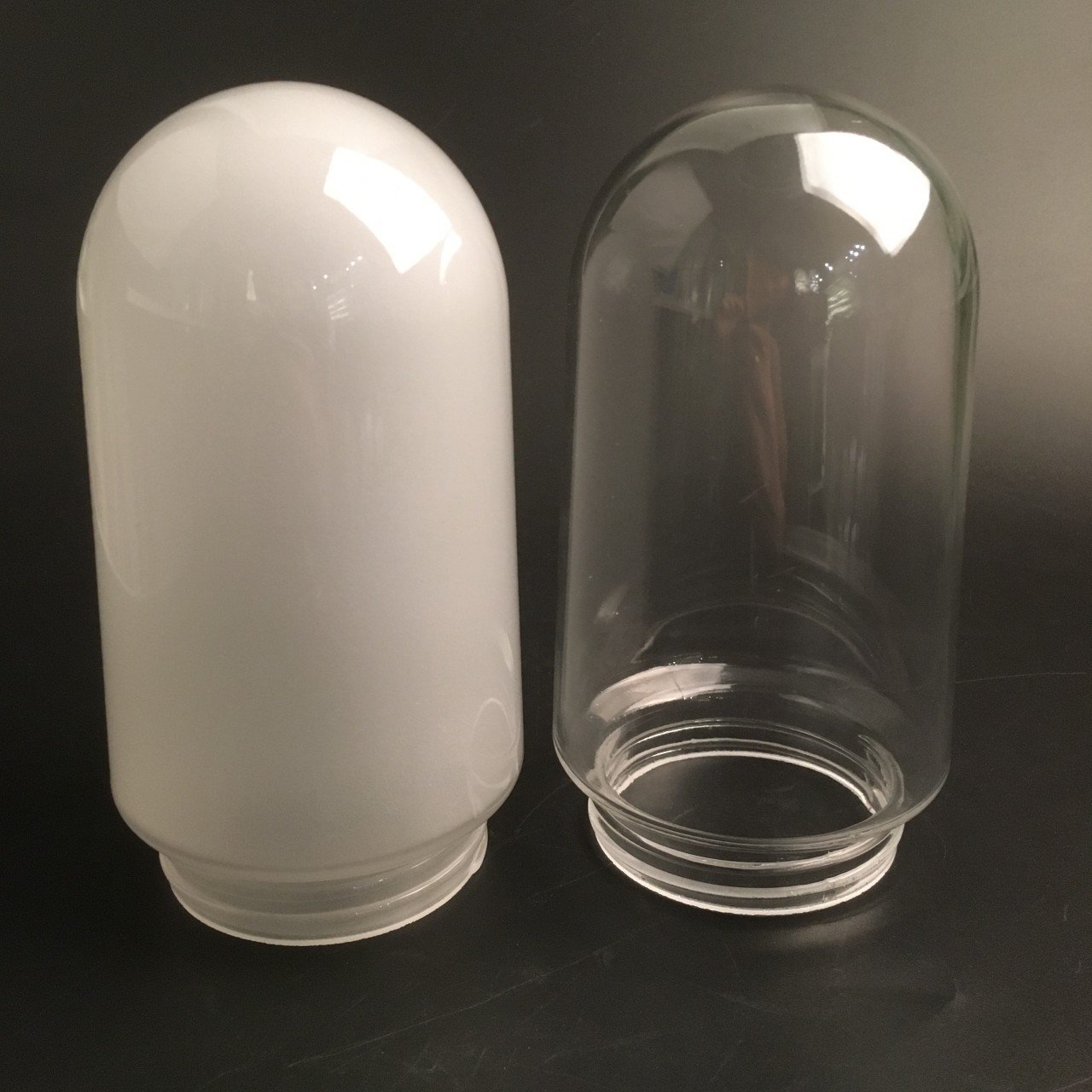
Define Function, Material and Service Conditions
Begin with what the glass must do in the product. Identify the features that locate it, retain it, provide clearance, contact a gasket or establish an optical effect. Mark the visible surfaces separately from hidden mounting regions.
Then describe temperature changes, loads, cleaning and other relevant exposure. Soda-lime glass is a composition family, not a complete performance specification. Forming, surface condition and installation influence how the finished component behaves.
For an illuminated cover, a thick rim may support attachment while the body controls the visible light effect. Altering the rim or wall profile can affect both functions. Review a section through the assembly rather than optimizing the isolated outside contour.
Distinguish requirements that cannot change from features open to adjustment. That gives a manufacturing review a useful question to answer: which route and geometry can meet the required function? The general glass DFM guide explains the broader review before tooling.
Choose Blowing or Pressing Around the Controlled Surfaces
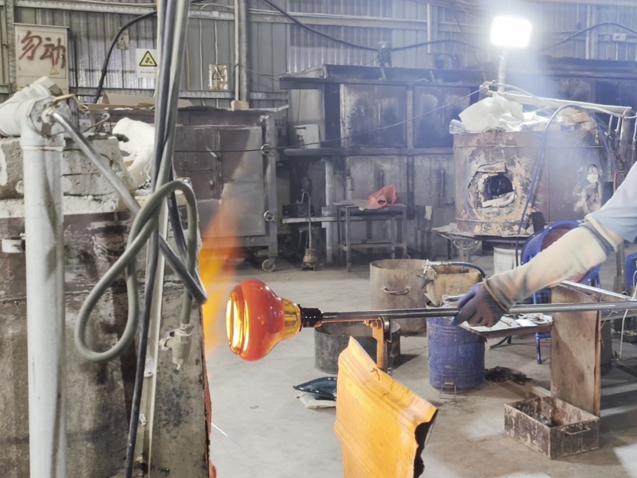
Blowing expands hot glass into a hollow shape. In mold blowing, the outer body contacts the mold while the inner wall develops as the glass is distributed. A mold-defined outside diameter and a nominal wall thickness do not automatically establish a separately controlled inner cavity.
Pressing shapes glass between tooling surfaces. Corning’s ophthalmic-blank manufacturing description identifies the mold, plunger and ring as defining different blank features. This illustrates the tooling principle, not a dimensional capability for custom soda-lime components.

| Design requirement | Blowing review | Pressing review |
|---|---|---|
| Hollow rounded body | Check wall distribution, necks and openings. | Check whether the cavity and plunger can form and release the profile. |
| Defined internal clearance | Specify the clearance envelope and relevant wall locations. | Identify the tool-controlled surface and withdrawal direction. |
| Pattern or relief | Review expansion into the detail and its visible appearance. | Review filling, tool contact and release of the detail. |
| Critical seating surface | Identify whether it is formed or finished separately. | Identify which tool defines it and whether finishing is needed. |
Choose the route around the important surfaces, then review the remaining geometry. A change from blowing to pressing can change the tooling concept, wall profile and inspection approach; it is more than a change of machine.
The existing molten-glass blowing and molten-glass pressing guides cover the manufacturing processes. Precision molding of reheated optical preforms is a separate route; its published tolerances should not be transferred to these parts.
Design the Wall Profile and Thick Bases
Specify the wall through relevant sections, including shoulders, rims, bases, bosses and decorative projections. Distinguish a nominal target, an average thickness and a local minimum needed for function. They are different requirements and need different measurement definitions.
Hot glass distribution and cooling are linked to geometry. A thick base contains more material than the adjoining wall and can equalize in temperature more slowly. A thin shoulder beside it can behave differently during forming and cooling. SCHOTT’s TIE-27, Stress in Optical Glass explains how geometry, glass type and annealing conditions influence temperature distributions and residual stress. Its optical-glass schedules are not soda-lime production instructions.
Play animationClose animationWall-thickness transitions
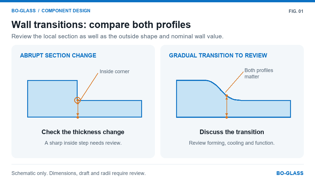
More thickness is therefore not an automatic cure for breakage. Extra material can help one mechanical requirement while changing weight, thermal gradients, transitions and contact loading. Removing material can create a different problem if a rim no longer supports finishing or assembly.
Show the complete wall profile and identify the regions that matter most. If only internal clearance is essential, define that envelope explicitly rather than imposing a precise inside contour that the function does not require. Where thickness controls acceptance, mark the locations and a suitable measurement method.
For service-temperature effects, see the thermal expansion and thermal-shock guide.
Blend Transitions and Define Openings and Rims
An external radius does not describe the internal junction. Rounding only the outside can leave a heavy section or a sharp inside transition. Review both surfaces in section, including the material left between them.
A gradual transition is often worth evaluating when adjoining sections differ substantially. Its length and curvature still have to preserve internal clearance, tooling access, the visible profile and any contact width. A smooth-looking outer silhouette alone does not establish a suitable section.
Openings need a defined finished condition. State whether the mouth is formed directly, cut after forming, ground or otherwise finished. Identify the region that contacts hardware and whether the edge is visible or handled during assembly.
Keep edge treatment separate from a functional seating requirement. A rounded edge, a flat annulus and an optically polished surface perform different jobs. Finishing a rim can change the component’s height, contact width and relationship to other features.
Check access through the opening for tools, internal inspection and the mating product. A narrow mouth can make an otherwise attractive body difficult to finish or verify. Put any required insertion or clearance envelope on the drawing.
Review Press Direction, Draft and Undercuts
A pressed shape must permit the tooling to enter, shape the glass and withdraw. Start by marking the proposed plunger motion and the opening direction of each mold section. Then look for geometry that obstructs those motions.
An internal recess wider behind a narrower opening can trap a straight-withdrawing plunger. An external projection can obstruct removal from a one-piece mold. The issue is the relationship between the feature and the withdrawal direction, rather than whether the feature looks simple in the finished part.
Play animationClose animationPlunger withdrawal and part removal
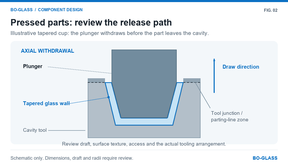
UNIDO’s historical Glass and Glass Making, in its pressing section, describes the roles of mold, plunger and ring, withdrawal of the plunger and use of divided molds where a pressing cannot be drawn from a one-piece body. These are forming principles, not current equipment specifications.
Draft provides taper in relation to release. The required geometry depends on depth, surface detail, tooling arrangement, glass condition and the actual process. There is no universal draft angle that makes every soda-lime part releasable.
| Feature requiring review | Possible design discussion |
|---|---|
| Deep internal cavity | Plunger access, taper, clearance and withdrawal path. |
| Undercut or reverse taper | A profile change, divided tooling or an alternative operation. |
| Fine recessed detail | Filling, local cooling, surface expectations and tool release. |
| Removal contact area | Where tooling or handling can contact the part without compromising function. |
Agree the tool concept before treating a complex recess as an accepted production feature. Do not assume that every mold arrangement, removable element or ejection mechanism is available for the project.
Plan Blown Features and Parting-Seam Zones
In a blown component, local expansion and glass distribution are important alongside the mold outline. Broad bodies, narrow necks, shoulders and sharp-looking details do not necessarily develop the same wall profile. Review the material around a transition rather than specifying the outside feature alone.
For a neck or mouth, identify the fit requirement and how it will be formed or finished. For a deep body, identify any internal clearance that cannot be inferred from the outside shape. For a decorative projection, explain whether its exact profile or its overall appearance is the controlling requirement.
Mold parting lines should have permitted and excluded zones. A seam crossing a gasket track, seating face or optical region can matter even if it is hidden after assembly. A seam on a visible surface needs an appearance criterion and agreed viewing conditions.
Treat seams, surface texture and tool access as connected decisions. Moving the parting line may change the mold layout or which details can release. Reducing the visible seam is not necessarily equivalent to removing every trace by a later operation.
Record the acceptable seam location on the drawing or an approved marked image. Evaluate representative samples in the intended orientation, including the illuminated condition when relevant.
Define Mounting, Fit, Datums and Tolerances
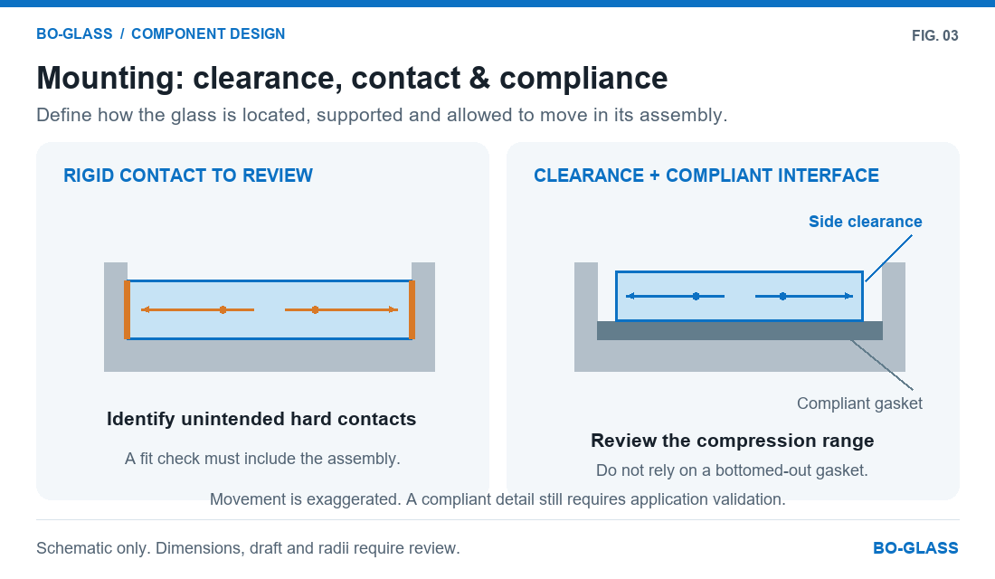
Start with the load path: where does the assembly locate the glass, where does it retain it, and where can it accommodate variation or movement? Avoid leaving contact with a screw, clamp or sharp metal feature undefined.
A gasket or compliant support can distribute contact and accommodate some movement, but its performance depends on material, geometry, compression and environment. A rigidly constrained fit can develop loads as glass and metal change temperature. Clearance and compliance are design variables to assess, not automatic guarantees against cracking.
Play animationClose animationRigid contact, clearance and compliant support
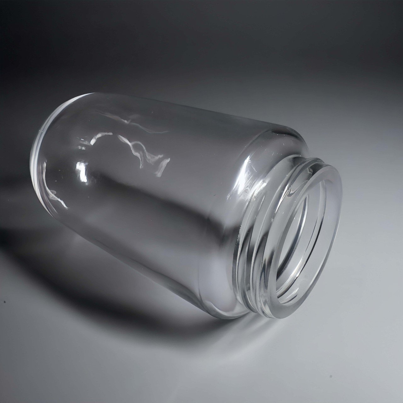
Threads and sealing interfaces
Show the thread, termination, rim, gasket and any travel stop together. Thread engagement, seating position and gasket compression interact. A cover that turns freely can still seat unevenly; excessive tightening can introduce unwanted glass loads.
The published BO-GLASS threaded-cover case describes checking custom covers against the actual metal base and performing sealing checks. Its relevant lesson is to evaluate the assembly interface. It does not establish a rating or default test plan for a new design.
References and measurement locations
Choose datum features that represent how the product locates the glass. A seating annulus may establish an axial reference, with a locating feature establishing position or an axis. A decorative surface is a poor reference if its allowed variation is unrelated to fit.
ISO 5459:2024 addresses datum terminology and indication; ISO 1101:2017 provides the language for geometrical specification. Those frameworks do not choose the correct datum features or tolerances for the component.
A diameter tolerance alone does not establish roundness, seating-face orientation or alignment to another feature. Specify what controls function, at which section and relative to which reference.
Target dimensions and demonstrated capability
A target dimension states design intent. An acceptance tolerance defines permitted variation. Neither is evidence that a proposed process can achieve the requirement repeatedly.
Review critical features against forming, finishing and verification. If a necessary interface cannot be produced directly, consider a finishing operation or a revised interface. Keep the tolerance required for function rather than widening it without evaluating the assembly.
One approved sample does not characterize long-term process variation. Agree what production evidence is needed and how measurements will be made. NPL’s coordinate-measurement uncertainty guide explains the importance of task-specific uncertainty; instrument resolution alone is not proof that a tight requirement can be verified.
Plan Holes, Secondary Processing and Optical Zones
A hole or slot needs more than a diameter. Show its position relative to edges and references, the surrounding wall, required edge condition and the way load enters it. Check tool access and support on the actual curved or irregular surface.
Forming a feature directly and machining it afterward can produce different edge conditions and dimensional relationships. Secondary work needs suitable stock, access and a way to hold the part without damaging important surfaces. Review whether the resulting feature still meets the assembly and strength requirements.
SCHOTT’s BOROFLOAT® 33 mechanical-properties guidance identifies surface defects, edge processing, drilled holes, loading and installation as factors affecting glass strength. Its borosilicate strength values are not transferred to soda-lime parts here.
If thermal toughening is proposed, machining and treatment sequence must be settled first. Pilkington’s toughened-glass guidance requires cutting, drilling and edgework before toughening. Confirm that the component and intended treatment are compatible rather than assuming every formed shape can be processed in the same way.
Mark optical zones separately from mounting and decorative areas. Mold contact, pattern, seams, wall distribution and frosting coverage can affect the optical result. An appearance sample alone does not define transmission or light distribution. See the soda-lime optical transmission guide for those requirements.
Account for Annealing, Residual Stress and Validation
Glass geometry remains important after the shape has formed. During cooling, regions at different temperatures can contract differently. The cycle through which stress can relax influences the stress remaining in the finished component.
Annealing reduces manufacturing-related residual stress; it does not erase scratches, correct a trapped-tool geometry or convert soda-lime glass into a low-expansion material. A thick base or heavy rim belongs in the annealing review as well as the dimensional model. SCHOTT TIE-27 discusses these relationships for optical glass; its numerical specifications are not adopted as custom soda-lime acceptance limits.
Plan residual-stress examination around the material, optical path and component geometry. A polarized-light appearance is not, without a suitable method and interpretation, a universal strength measurement.
Separate checks of the component from validation of its function in the product. Dimensions, appearance, residual stress, installation and service testing answer different questions. Record the applicable methods and acceptance conditions instead of describing sample approval as proof of every possible use.
Revisit relevant checks when material, geometry, finishing, tooling or mating parts change. A modified gasket or newly machined rim can alter an interface that previously passed qualification.
Prepare the Drawing and RFQ
Supply a dimensioned drawing and sections that expose the important relationships. Include the current revision, units and a model or marked photographs where they help explain the shape. Identify unresolved requirements early.
| Item to provide | Information needed for a useful review |
|---|---|
| Function and environment | What the glass does, operating temperatures and changes, loads, cleaning and other exposure. |
| Material and route | Required composition or appearance, proposed blowing or pressing route, and alternatives open for discussion. |
| Wall profile | Sections through the body, base, rim and transitions; distinguish targets from local acceptance requirements. |
| Tooling and seams | Proposed withdrawal direction, internal recesses, acceptable parting-line areas and critical visible zones. |
| Assembly | Mating-part drawings, gasket and fastener information, locating surfaces, clearances and installation procedure. |
| Dimensions | Critical features, datum references, tolerances and measurement locations. |
| Finishing and optics | Formed versus finished features, treatment coverage and functional optical areas. |
| Verification and quantity | Sample needs, expected order quantities, required inspections, service tests and records. |
For a hypothetical cover, label the seating annulus A, the locating feature B and the wall-check positions C. Link those labels to complete drawing requirements and suitable methods; the letters alone are not a finished specification.
Before tooling, resolve the route, functional geometry, references, finishes and acceptance basis. Confirm which sample checks establish feasibility and which production checks control subsequent orders. Use the ordering guide for the commercial stages.
Is there one minimum wall thickness or draft angle?
No universal value is given here. Geometry, material, tooling, finishing and service requirements determine the review. Submit the full section and function rather than applying a number from an unrelated product.
Can a metal-part tolerance block be applied to formed glass?
Review it feature by feature. Preserve necessary functional limits, then confirm the manufacturing route, definition and measurement method for each important characteristic.
Does polishing every surface improve the design?
Choose the required result first. A sealing face, decorative surface and optical zone can need different conditions. Polishing is a process choice and can change dimensions; it does not replace a functional requirement.
Request a Component Design Review
Send your drawing, sections, mating-part information, intended quantity and service conditions. Mark the features that control fit or performance and identify details that can be adjusted.
Include the inspection or optical specification if one already exists. A clear statement of function helps the review connect material, shape, manufacturing and verification before tooling is finalized.
References and Scope
Sources checked on 16 November 2026. These references support forming, stress and specification principles. Product-specific process limits, strength values and certification claims are not transferred to BO-GLASS custom components.
- Corning — Manufacturing Techniques: mold, plunger and ring principles in an ophthalmic-blank context.
- UNIDO — Glass and Glass Making, 1977: historical pressing and tool-withdrawal principles.
- SCHOTT — TIE-27: Stress in Optical Glass, August 2023: geometry, thermal history and residual stress.
- SCHOTT — BOROFLOAT® 33 Mechanical Properties: effects of surface condition, machining, load and installation; not soda-lime strength data.
- ISO 5459:2024 — Datums and Datum Systems and ISO 1101:2017 — Geometrical Tolerancing: official scope descriptions; adopting a standard requires the full applicable requirements.
- NPL — Coordinate-Measuring Machine Task-Specific Measurement Uncertainties, GPG130: measurement uncertainty for coordinate-measurement tasks.
- Pilkington — Toughened Glass: machining sequence before thermal toughening in its stated product context.
Contact Us
Discuss Your Custom Glass Project
Share your drawing, photos or dimensions, together with the intended use and target quantity. We will review your requirements and discuss the next steps.
Sales Enquiries
Email sales@bo-glass.com with your part description, intended use and target quantity.
Send Your Design
Use the form to upload a drawing or describe an existing part. Mark critical dimensions and tell us which surfaces or features matter most.
Request a Custom Glass Quote
Upload a drawing or share dimensions, quantity, intended use and finish. Include any heat, pressure or chemical exposure.
Your drawings remain confidential.
We use the contact details you provide to respond to your enquiry. See our Privacy Policy for more information.