
BO-GLASS / TECHNICAL MATERIALS
Soda-Lime Glass Thermal Expansion, Thermal Shock and Temperature Limits
A useful thermal specification describes what happens to the glass, where it happens and how the part is supported. A heater setting or a single “maximum temperature” leaves these questions unanswered.
This guide explains how to turn operating conditions into a material and component review. For composition, forming routes and general selection, see our soda-lime glass overview.
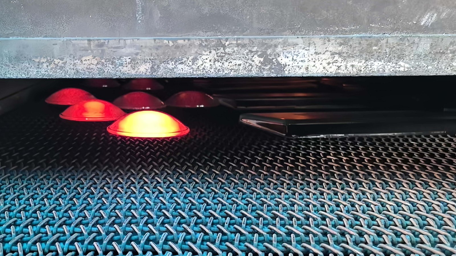
Separate Temperature, Temperature Difference and Temperature Change
Begin with three questions:
| Question | Information needed | Decision it supports |
|---|---|---|
| How hot or cold does the glass become? | Actual glass temperatures and exposure duration | Material, finish and assembly suitability |
| How different are temperatures within the part? | Temperatures at the rim, body, inner surface and outer surface | Review of differential expansion |
| How quickly do conditions change? | Heating, cooling, start-up, shutdown and splash events | Selection of representative transient tests |
A stable operating condition and a short cleaning event can require different evaluations. Include both in the design brief rather than assuming that the longest operating period is necessarily the most demanding event.
What the Characteristic Temperatures Mean
Pilkington ATS-129, September 2026 provides these references for soda-lime-silica float glass:
| Characteristic | Published reference | Condition |
|---|---|---|
| Linear thermal expansion coefficient | 8.3 × 10⁻⁶ K⁻¹ | 75–575°F; approximately 24–302°C |
| Softening point | 715°C | Published softening-point test |
| Annealing point | 548°C | Published stress-relaxation characteristic |
| Strain point | 511°C | Published stress-relaxation characteristic |
Optiwhite™ temperatures differ. These values do not specify every blown or pressed formulation or establish finished-part operating limits.
The terms describe different behavior. Softening point concerns deformation under a defined test. Annealing point identifies a viscosity at which stress relaxation occurs relatively quickly. Strain point corresponds to a higher viscosity and much slower relaxation. Corning’s technical definitions, printed page 25 describe relaxation on timescales of minutes and hours, respectively.
An annealing-point value is not an annealing schedule. The component must be heated, held and cooled in a way appropriate to its material and sections. Likewise, a temperature below the softening point is not automatically acceptable for a constrained, loaded or rapidly cooled component.
When discussing a proposed operating limit, ask what would constitute failure: cracking, unacceptable deformation, loss of fit, coating damage or failure of the assembled seal. The limit must address the relevant outcome and exposure duration.
Calculate Free Expansion Before Reviewing Restraint
Play animationClose animationUniform heating & free expansion
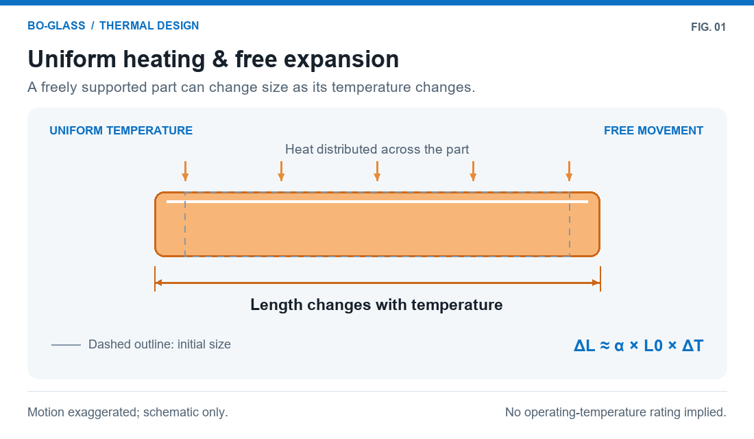
For a first dimensional estimate within an appropriate temperature interval:
ΔL ≈ α × L₀ × ΔT
- ΔL: change in length, in millimeters.
- α: mean linear expansion coefficient, in K⁻¹.
- L₀: original length, in millimeters.
- ΔT: temperature change; a Celsius temperature difference has the same numerical value as a kelvin difference.
Illustrative calculation: assume a freely expanding 120 mm glass feature warms uniformly from 30°C to 170°C. Using the reference coefficient above:
ΔT = 170 − 30 = 140 K
ΔL ≈ 8.3 × 10⁻⁶ K⁻¹ × 120 mm × 140 K = 0.13944 mm, approximately 0.14 mm.
The calculation assumes uniform temperature, free movement and a coefficient suitable for the interval. It estimates movement; it does not determine clearance, allowable stress or thermal-shock resistance.
For an assembly, prepare the corresponding movement estimate for the actual mating material. Then review the dimensional tolerances and contact arrangement together. Do not subtract two nominal expansion values and declare the remaining gap sufficient without checking the complete tolerance stack and actual temperatures of both parts.
Why Uniform Heating and Local Heating Behave Differently
A freely supported glass body can accommodate uniform heating by changing size. A nonuniform temperature field creates regions that would expand by different amounts if they were independent. Because they remain connected, stresses develop. Pilkington’s ATS-123 thermal-stress bulletin explains this mechanism for window glass, including the influence of cooler covered edges, localized heating, restricted heat removal and edge condition. Its building-glazing examples should not be transferred numerically to a molded cover.
Thermal shock describes a rapid change in thermal conditions. The temperature step between the environment and the glass is not necessarily the temperature difference inside the glass at a particular moment.
SCHOTT’s TIE-32, Thermal Loads on Optical Glass explains how relatively slow heat conduction allows surface and interior temperatures to differ. In a simple, freely supported part, rapid external surface heating tends to put the hotter surface into compression and the cooler interior into tension. Rapid surface cooling tends to reverse that pattern, placing the surface in tension as it cools and contracts ahead of the interior.
Local heating, geometry, mounting restraint and pre-existing residual stress can change the stress distribution. Heating and cooling with the same nominal temperature step therefore need not present the same cracking risk. Air cooling and liquid cooling also involve different heat-transfer conditions; equal nominal temperature steps do not make the tests equivalent.
Play animationClose animationLocal heating & mounting
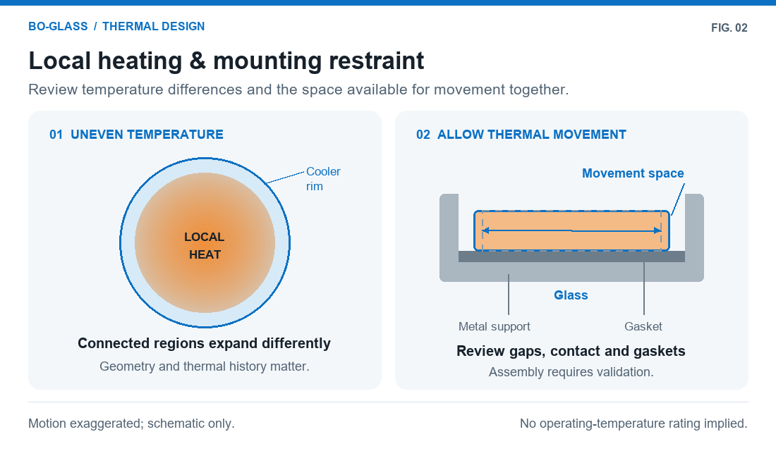
For design review, mark the heat source and expected heat-removal paths on a section drawing. Identify the locations where measurements would be needed to distinguish the proposed operating scenarios. Avoid deciding sensor positions only after a test produces an unexpected crack.
Wall Sections, Surface Condition and Metal Mounting
Ask whether the drawing describes the sections that control the thermal event. A single nominal wall value can hide a thick rim, narrow neck or substantial transition. Include these regions when preparing the sample and temperature-measurement plan.
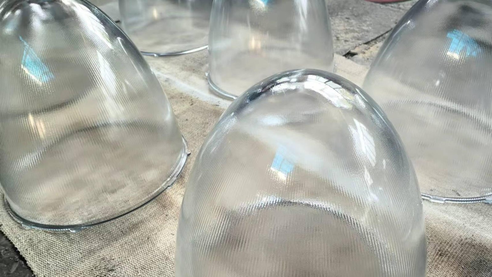
For comparable glass properties and surface heat-transfer conditions, a thicker wall generally takes longer to approach a uniform temperature through its thickness. During rapid heating or cooling, this can produce larger surface-to-interior temperature differences. This is a practical consequence of relatively slow heat conduction; it is not a universal thermal-shock rating based on thickness.
Increasing thickness may help meet some mechanical loading requirements while increasing transient thermal-stress risk. Review the wall profile, thick rims, abrupt transitions and mounting together, then include the relevant sections in temperature measurements and finished-component validation.
For lighting covers, also review how thickness and surface finish affect optical transmission.
Also document the condition in which the component will be tested. SCHOTT’s BOROFLOAT® 33 mechanical-properties sheet explains why glass strength depends on surface defects, processing, loading, environment and installation. Those principles are relevant to reviewing brittle glass; its borosilicate strength values are not soda-lime design values.
For a metal-mounted component, review these questions with the assembly designer:
- Which surfaces locate the glass, and which allow movement?
- Can the retaining ring, clips or screws create uneven contact?
- What happens at the minimum and maximum permitted gasket compression?
- Is assembly torque controlled, and does it reproduce the intended seating condition?
- Could thermal movement cause a previously separated metal feature to touch the glass?
TIE-32 also identifies contact with dissimilar-expansion materials and mounting restraint as thermal-design concerns. Review gasket and adhesive properties at their actual operating temperatures. A compliant detail on a room-temperature drawing still needs to function during the specified cycle.
For luminaire-level structural and safety questions, use our existing structural, thermal and safety design guide alongside the material review.
Build an Operating-Conditions Brief
Use measured information where available. Label estimates so that the validation plan can resolve them.
| Input | Record for the review |
|---|---|
| Component | Drawing revision, material proposal, forming route, wall profile and finish |
| Normal operation | Glass temperatures, locations, ambient range and time to steady operation |
| Transients | Start-up, shutdown, power interruption, ventilation changes and cleaning |
| Heating and cooling | Source location, distance, airflow, liquid contact and event duration |
| Duty cycle | Dwell time, cycle count and expected service pattern |
| Installation | Mating hardware, support surfaces, fasteners, gasket and assembly procedure |
| Other loads | Pressure, handling, vibration or mechanical loads present during heating |
| Acceptance | Required fit, appearance, sealing and functional results after exposure |
For an existing product, include temperature records and photographs of the installation. For a new design, distinguish confirmed requirements from assumptions that need measurement. An unverified estimate should remain visible in the review record until it is resolved.
Illustrative Engineering Situation: A Heated Cover and Retaining Ring
Consider a proposed soda-lime cover held in a metal ring. During normal operation, its body receives radiant heat while the seating region contacts a gasket. Maintenance may involve switching the source off and wiping the cover.
This is an illustrative design situation, not a BO-GLASS customer case or a qualified product. No operating temperature or acceptable cleaning procedure is implied.
An appropriate review would first separate three events: warm-up, steady operation and maintenance. Request the source position, mounting section and proposed cleaning instructions. Next, decide where temperature measurements are needed and which assembly variations deserve evaluation. These might include the permitted seating and gasket-compression conditions.
If the initial test addresses only steady operation in one nominal assembly, record that limitation. It has not answered the maintenance question or established performance for another retaining ring. Use the findings to decide whether to revise the heat path, mounting, cleaning procedure or material proposal before qualification.
Plan Finished-Component Validation
The following is a planning framework. The applicable procedure, equipment, laboratory, sample count and acceptance criteria must be agreed for the product; this list is not a claim that a particular test service is included.
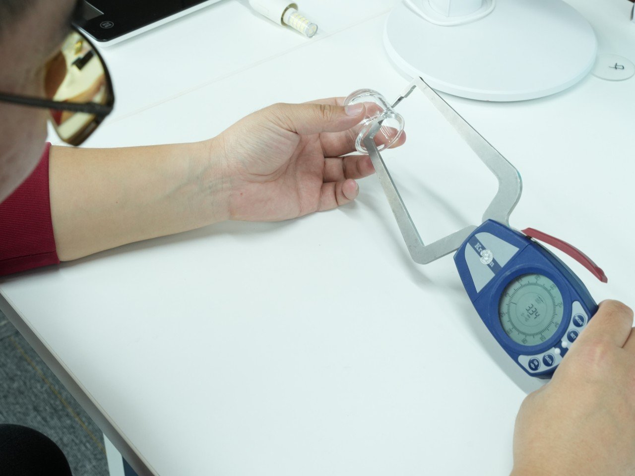
- Define the decision. State which drawing, material, mounting arrangement and service conditions the evaluation is intended to support. Identify the applicable product requirements with the responsible product engineer or laboratory.
- Select representative samples. Record the production route, finish, measured wall sections and initial condition. Decide how normal manufacturing and assembly variation will be represented.
- Document the assembly. Use identified mating hardware and gaskets. Record fastener settings, seating and contact conditions so the setup can be reproduced.
- Measure the event. Record actual glass and relevant hardware temperatures, sensor locations and timing. Specify a measurement arrangement suitable for the surface and required response. A chamber or heater setpoint alone does not document the glass temperature field.
- Apply the agreed sequence. Include the relevant starting condition, heating, dwell, cooling and repetition. Keep exploratory trials distinct from a qualification sequence with predetermined acceptance criteria.
- Inspect and assess function. Define checks before and after exposure. Depending on the product, these may address cracks, chips, deformation, fit, surface changes or assembly sealing. Record failures and deviations as well as passes.
- State what the evidence covers. Identify tested revisions, sample quantities and conditions. Establish which changes require review or further testing, such as altered sections, finishes, hardware or operating cycles.
A successful sample is evidence about the tested arrangement. It does not, by itself, establish a universal soda-lime temperature rating or prove every unit’s performance throughout service.
When to Evaluate Another Material
Evaluate alternatives when the proposed soda-lime component cannot be supported by an acceptable combination of geometry, mounting, operating conditions and validation.
For example, SCHOTT reports a mean expansion coefficient of 3.25 × 10⁻⁶ K⁻¹ over 20–300°C for BOROFLOAT® 33 in its thermal-properties sheet. This named borosilicate grade illustrates a lower-expansion option, not a specification for all borosilicate glass.
Compare complete proposals, including available shapes, finishes, mounting and verification. Explore our borosilicate components page when a different material deserves review. A material substitution should trigger an updated assessment rather than automatic acceptance of the previous test plan.
Technical Questions
What is the maximum safe temperature for soda-lime glass?
There is no single answer for all components. Define the composition, exposure duration, temperature distribution, loads, mounting and acceptable outcome. A softening-point value cannot replace that assessment.
Does a thicker wall automatically provide better thermal performance?
No. Under comparable material and heat-transfer conditions, a thicker section generally equalizes more slowly and can develop larger transient temperature differences. Select the wall profile against both thermal and mechanical requirements, including thickness transitions and mounting, then validate the assembled component.
Will annealing or strengthening solve the problem?
Annealing uses a controlled thermal cycle to reduce residual stresses left by forming and cooling. It does not turn soda-lime glass into a low-expansion material. Corning’s technical definitions, printed page 25 also note that annealing can slightly affect the reported expansion coefficient; use data for the specified composition and material condition.
Thermal toughening (physical tempering) deliberately creates surface compression, balanced by tension within the glass. This can improve resistance to applied mechanical and thermal stresses where the process is suitable, as described in Pilkington’s toughened-glass overview. Its benefit comes from this prestress, rather than conversion to a low-expansion glass.
Neither treatment provides a universal operating-temperature rating or corrects an unsuitable mounting arrangement. Review the failure mechanism, process compatibility, geometry and finished assembly before qualification.
Can an expansion calculation replace a thermal-shock test?
No. Free-expansion arithmetic estimates movement. It does not reproduce transient temperature fields, surface condition or the loads in the assembly. Use it to prepare the review and identify questions for analysis and testing.
Discuss Your Thermal Application
Send the component drawing, intended glass, operating cycle and mounting details. Include measured temperatures if available, anticipated cleaning or cooling events, quantity and the performance you need to demonstrate.
References
Sources checked on 13 November 2026. Published values apply to the materials and conditions identified by their suppliers.
- Pilkington — ATS-129, September 2026: float-glass reference data.
- Corning — Tubing Specifications: Definitions and Supporting Information: characteristic temperatures, printed page 25.
- Pilkington — ATS-123, September 2026: flat-glass thermal-stress mechanisms.
- SCHOTT — TIE-32, Thermal Loads on Optical Glass, October 2018: transient stresses and installation considerations.
- SCHOTT — BOROFLOAT® 33 Mechanical Properties: factors affecting glass strength.
- SCHOTT — BOROFLOAT® 33 Thermal Properties: grade-specific thermal data.
- Pilkington — Toughened Glass: surface compression and thermal toughening.
Contact Us
Discuss Your Custom Glass Project
Share your drawing, photos or dimensions, together with the intended use and target quantity. We will review your requirements and discuss the next steps.
Sales Enquiries
Email sales@bo-glass.com with your part description, intended use and target quantity.
Send Your Design
Use the form to upload a drawing or describe an existing part. Mark critical dimensions and tell us which surfaces or features matter most.
Request a Custom Glass Quote
Upload a drawing or share dimensions, quantity, intended use and finish. Include any heat, pressure or chemical exposure.
Your drawings remain confidential.
We use the contact details you provide to respond to your enquiry. See our Privacy Policy for more information.