
Borosilicate Glass Lampworking Process Control
Borosilicate lampworking reshapes tubes, rods and prepared glass parts through local heating, movement, blowing, tooling and joining. Repeatability depends on coordinating these actions so the required bore, wall distribution, alignment and surface condition are preserved throughout the forming sequence.
Control sequence: define the required result → establish stage conditions → coordinate heating and movement → verify functional geometry → manage deviations → connect forming records to final inspection.
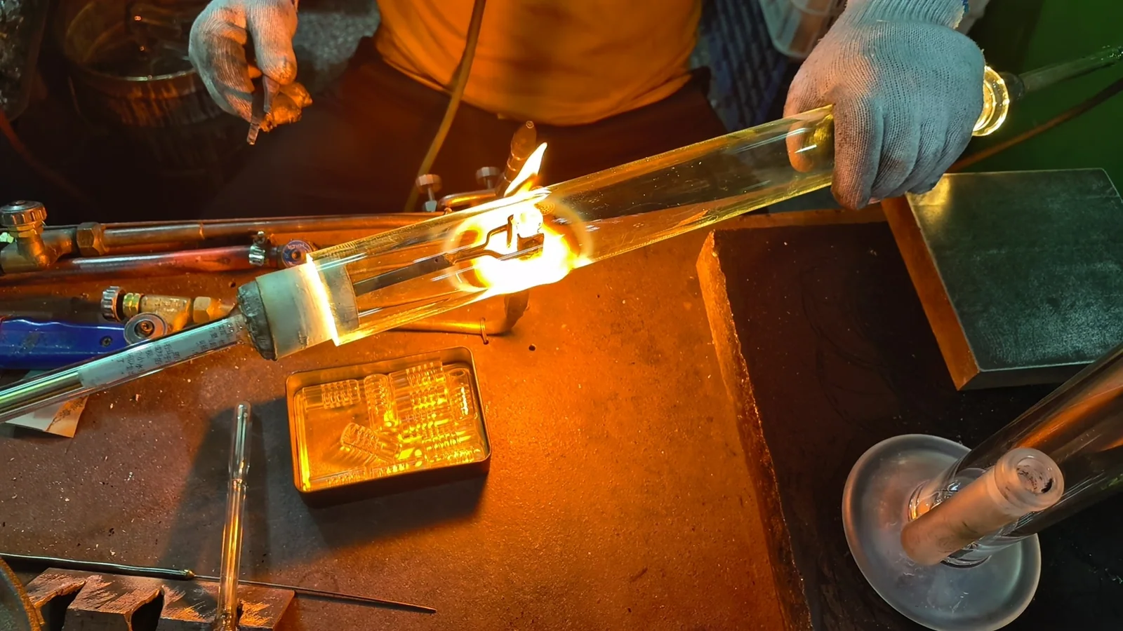
Plan the Forming Sequence and Control Criteria
Start with the finished drawing and work backwards. Identify sealing surfaces, passages, connections, mounting points and other features that determine whether the component functions. Decide when each can be formed, supported and inspected. Use the lampworking design guide to establish these drawing requirements before developing the process.
Separate four kinds of control so an equipment setting is not mistaken for a product requirement:
Swipe horizontally to view all columns.
| Control concept | Purpose | Practical example |
|---|---|---|
| Target conditions | Define the intended conditions for normal production | Approved heating sequence and movement for a particular neck |
| Validated operating range | Identify combinations demonstrated to produce acceptable results | Permitted stock variation with the tested heating and forming conditions |
| Action and stop conditions | Define when to adjust, hold, interrupt or seek review | Loss of alignment, unexpected deformation or inadequate remaining allowance |
| Product acceptance limits | Define what the finished component must satisfy | Specified bore, wall thickness, joint position and surface condition |
Individual variables can remain within their listed limits while their combination is untested. Longer heating combined with higher forming pressure may have a different result from either change alone. Trials should address relevant interactions and realistic stock variation.
Plan stock preparation, heating, primary forming, joining, final shaping and transfer as linked stages. Each needs an entry condition, controlled action, completion criterion and interruption response. Completion may mean reaching a reference profile, establishing joint continuity or confirming shape retention before support changes; elapsed time alone may not establish readiness.
Sequence operations around access. A sidearm can prevent continuous rotation, while reheating a late joint may disturb an earlier flange. Preserve forming allowance and inspection access until the relevant features have been verified.
Manage Heating and Forming Response
Establish the working temperature distribution
Progressive heating prepares the intended length and circumference for deformation while managing temperature differences around adjoining glass. Starting temperature, wall thickness, existing joints and attached masses affect the required approach. Fresh tubing and a partly completed assembly should not automatically follow the same heating sequence.
Define burner coverage, working position, exposure sequence and movement of the glass or flame. The region to be formed must become workable while surrounding features retain sufficient stiffness. Excessive heating outside that region can allow completed geometry to move.
Relate the procedure to observable response: where elongation or expansion begins, whether deformation is distributed, and how much useful working time remains after leaving the flame. These observations support a developed procedure; they are not precise glass-temperature measurements.
Record applicable supply and flame conditions
Record the burner and tip, active stages, permitted fuel and oxygen source, and the gas-delivery conditions relevant to repeatability. Where pressure or flow is recorded, identify the measurement point, units and operating state, including simultaneous demand where relevant. Manufacturer consumption data are tied to stated burner configurations and supply conditions.[1]
A burner setting does not directly establish temperature throughout the glass wall. If temperature measurement is used, confirm its suitability for the material, viewing geometry and flame environment.
Coloured grades may need different flame atmospheres or heating approaches. Apply guidance for the actual grade and verify the processed appearance; one colour's working instructions should not become a universal borosilicate recipe.[2]
When heating response changes unexpectedly, investigate material condition, delivery stability, burner configuration and movement before extending exposure or changing another process input.
For equipment selection and support arrangements, see the torch, tooling and workholding guide.
Coordinate Rotation, Alignment and Movement
Rotation helps distribute heating around the circumference and maintain shape as glass softens. For hand work, control rotational consistency, centreline alignment and coordination between the hands. For lathe-assisted work, establish the operating stage, rotation, support positions and axial movement.
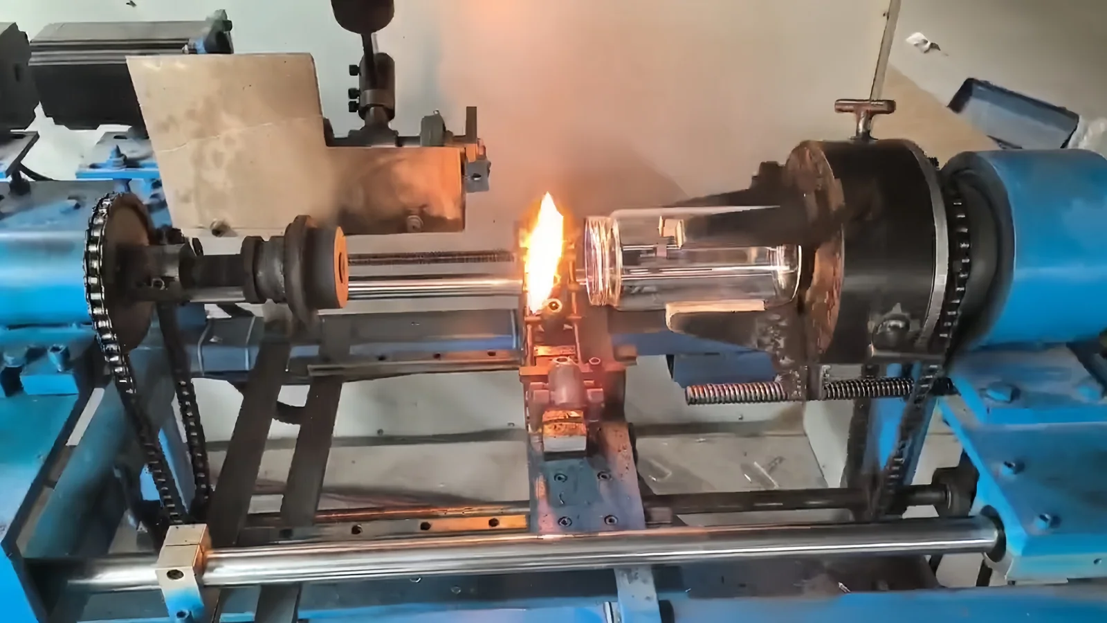
When both ends are driven, use the machine's approved arrangement for coordinated rotation. Scientific glassworking lathes support synchronous manipulation while softened glass is redistributed.[3] Increasing speed alone does not correct an unsuitable heating pattern; burner coverage, stock dimensions and exposure remain relevant.
Define movement from identifiable starting references. Pulling, approaching a joint or changing support should occur at the intended forming condition, with enough clearance for the developing assembly. A repeatable travel distance can give different results if the heated length changes.
For parts that cannot rotate continuously, establish burner movement or controlled repositioning around the working region. Include the balance and support of attached branches and fittings.
Distinguish seating movement, slipping contacts and support deflection from deformation of the hot glass. Resolve the source of lost alignment before continuing correction. Record any support change that alters access or the way the workpiece responds.
Control Tube Drawing, Expansion and Bending
Drawing, stretching and necking
Pulling redistributes softened glass along the working axis. Control the heated length, temperature distribution, timing and extent of movement, together with rotation and any pressure used to retain the bore.
Elongating a solid rod generally reduces its cross-sectional area. Tubing requires attention to both outside profile and internal passage. Establish taper length, transition shape and remaining wall allowance instead of treating an outside diameter as the complete result.
Repeated correction of an already thin region can consume the available material. If a neck consistently needs extra work, review starting stock, heated-zone length and the earlier forming stages. Incoming dimensions and material identity should follow the tube and rod selection guide.
Expansion and internal forming pressure
Expansion depends on the pressure difference across the wall acting with glass viscosity, wall thickness and heated area. The same pressure input may cause little movement in one condition and rapid expansion in a hotter or thinner region.
Define the region to expand, connection and venting state, pressure application and release, and the support used while shape is retained. Burner gas pressure and internal forming pressure are separate variables and must be recorded separately.
Where forming pressure is measured, identify sensor location and reference basis. An upstream reading may differ from pressure within the part during flow. Use a forming supply appropriate to the process, with suitable regulation and relief where required. Review the pressure path whenever an opening is closed or a branch is added.
Bending and bore retention
Make the intended bend region workable while supporting adjacent sections. A short heated zone can concentrate deformation; an unnecessarily broad zone can disturb surrounding geometry. Where blowing assists bore retention, coordinate it with the softened region.
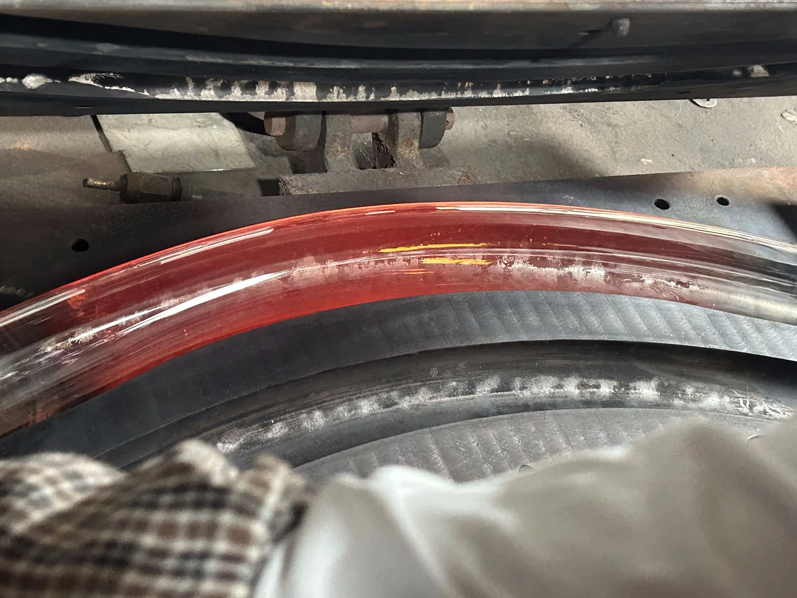
Control bend plane, angle, centreline radius and tangent positions. Assess ovality, local thinning and passage restriction at the bend and its transitions. Account for the weight of sidearms or fittings, especially when their position changes during the movement.
Form Openings, Rims and Closed Ends
Openings, rims and flanges
Match forming controls to the interface's function. A handling rim, hose connection and gasket flange can require different profiles and finishing routes.
Control available glass, heating depth, circumferential coverage, tool position and contact sequence. Widening an opening redistributes material around the edge; gathering a heavier rim creates a different local section. Check the opening, roundness, rim thickness and relationship to the component axis at the appropriate stage.
Specify whether a sealing face is formed directly or completed by grinding and lapping. Fire polishing rounds the heated edge, whereas lapping can establish a flat sealing surface.[4] Preserve sufficient allowance for the selected finish without relying on later work to recover an unsuitable section.
End closure and bases
Closing a tube gathers and fuses glass into an end profile. Evaluate the central closure, surrounding wall and transition into the body; a smooth exterior may conceal an uneven section or incomplete closure.
Define whether the result is a rounded end, standing base, contact ring or blank for subsequent machining. For a standing feature, establish contact geometry, tilt and rocking requirements. If an operation fully encloses the part, account for trapped gas and subsequent heating in the manufacturing plan before closure.
Join Tubes, Branches and Solid Attachments
End-to-end joints
Confirm glass compatibility, cleanliness, end preparation and the relationship between wall sections. Similar outside diameters do not ensure that the joining walls meet correctly, and a shared borosilicate designation does not establish compatibility.
Coordinate heating of both regions, axial alignment and circumferential fusion. Unequal wall sections can require different heat exposure. Initial contact may leave a thick seam; excessive stretching can produce local thinning. Develop the internal and external transition together.
Treat temporary attachment as an intermediate stage. Establish completion around the joint before removing support or beginning a dependent operation. Include bore continuity, local thickness and alignment in the verification plan, with leak or service-related tests where specified.
Sidearms and branch connections
Control branch position, angle, opening size and material around the root. The opening must provide a workable joining region while preserving the required parent-wall section.
Establish access to the full connection and support the branch against unwanted movement while its root is soft. Long or heavy sidearms can pull on the joint. Plan the order of multiple branches so later work remains accessible and does not disturb earlier connections.
Assess passage continuity through the root as well as external position. A visually complete connection can still contain a restriction or an unsuitable wall transition.
Handles, feet and solid features
Added masses respond differently to heating and cooling from a thin hollow body. Establish the attachment footprint, compatible glass combination and thermal preparation of both regions. Heating only the addition may leave the parent glass insufficiently prepared; excessive parent-wall heating can distort the body.
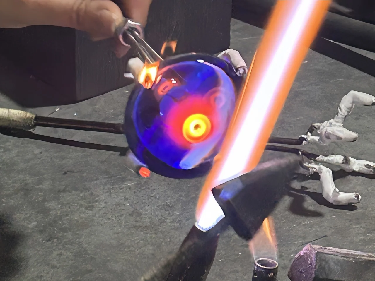
For a two-point handle, develop both connections without forcing the feature into position. Include the added mass in the annealing and support plan. Load-bearing attachments require the agreed geometry and functional verification, with finished position assessed after release from forming fixtures.
Verify Wall Thickness and Functional Geometry
Starting stock dimensions cannot establish the dimensions after glass has been redistributed. Link each functional requirement to a location, method and inspection stage.
Swipe horizontally to view all columns.
| Characteristic | What to verify |
|---|---|
| Outside profile | Diameter, taper or contour relative to the drawing reference |
| Internal passage | Minimum bore, continuity and local restrictions |
| Wall distribution | Minimum thickness and permitted variation at designated regions |
| Inner-to-outer relationship | Defined eccentricity or concentricity requirement, where relevant |
| Feature alignment | Position and orientation relative to drawing datums |
| Joint transition | Continuity and local section through the connection |
Choose methods suitable for curvature, material and access. Development samples may need sectioning or another appropriate method to establish wall distribution where routine inspection cannot reach. Use those results to determine which production checks can reliably detect relevant variation.
Hot templates and in-process gauges guide forming. Their readings need a demonstrated relationship to the cooled geometry. Likewise, holding a branch at the correct angle in a fixture does not establish its position after release.
Apply finished acceptance limits after the required annealing, cooling and secondary finishing. Keep forming allowances and intermediate targets separate from those limits. For regions that become inaccessible, specify the checks before closure and any additional evidence required from the completed part.
Limit Final Corrections and Flame Polishing
Flame polishing and local adjustment redistribute material. They can change opening size, edge radius, length and wall distribution, so include them in the controlled forming sequence.
Define the permitted correction region, features that must remain stable, remaining allowance and method of checking the result. Establish conditions requiring a hold or review, such as loss of a critical reference, inadequate wall allowance or distortion spreading beyond the intended area.
Record additional heating and reshaping as interventions, including the annealing and reinspection required afterwards. Repeated correction changes thermal history and can progressively disturb nearby features. When one characteristic can only be recovered by compromising another, review the earlier process rather than extending correction indefinitely.
A smooth surface does not establish complete joint fusion, optical performance or suitability for a service load. Release the corrected component against the affected functional requirements and the agreed inspection plan.
Manage Interruptions and Transfer to Annealing
Establish a recovery route
An interrupted component has a different thermal history from one following the continuous sequence. Record the stage, reason, elapsed interruption, current shape and relevant support condition. Recovery must account for cooling, existing joints and added masses.
Define when an approved recovery procedure applies and when the part requires review. Do not restart a substantially cooled assembly using assumptions developed for glass that remained hot. Unknown history, visible damage or loss of required geometry may place a part outside the approved recovery scope.
Preserve the part through transfer
Plan the condition at the end of forming, any intermediate hold, handling route, supports, receiving space and kiln-entry conditions. Include a response to unavailable kiln space or an unexpected transfer delay. Support heavy joints and projecting features without forcing alignment.
Local reheating during fabrication does not replace a validated annealing cycle or demonstrate acceptable residual stress. Annealing relies on controlled thermal treatment and cooling to reduce internal stress.[5]
Hot transfer and controlled reheating after cooling are different routes; qualify the chosen route for the component. Link the forming record to the annealing batch. Detailed schedules, controlled cooling and residual-stress inspection belong in Annealing, Cooling and Quality Inspection of Lampworked Borosilicate Glass.
Record and Maintain a Repeatable Process
Connect controllable inputs, observed response and final results. Manual processes can use structured instructions, reference profiles and recorded checks; instrumented operations may also capture pressure, movement and timing.
Swipe horizontally to view all columns.
| Record group | Conditions that make the record useful |
|---|---|
| Material and stock | Grade, lot, starting dimensions and relevant incoming results |
| Burner supply and flame | Fuel and oxygen source, applicable delivery measurements under stated demand, burner stages and flame condition |
| Heat distribution | Position, coverage, exposure sequence and the observed forming response |
| Rotation and movement | Stage, reference position, synchronisation, support and measured settings where applicable |
| Internal forming pressure | Measurement location, reference basis, connection state and application sequence |
| Tools and contacts | Tool identity, condition, contact position and sequence |
| Interruptions and corrections | Affected stage and parts, reason, recovery or correction route and review decision |
| Transfer and results | Transfer conditions, annealing batch and linked finished-inspection results |
When a deviation appears, identify affected parts and the last known acceptable condition. Keep the recorded change distinguishable from normal production so its effect can be reviewed. An observed association between an input and a defect is a starting point for investigation, not proof of a single cause.
A successful sample establishes feasibility under those conditions. Demonstrate repeatability across representative parts, stock variation and operating conditions before extending the approved scope. Where statistical capability is used, compare a stable process with the relevant specification using suitable data and assumptions; an index for one dimension does not represent the entire assembly.[6]
Review changes to grade, stock dimensions, burner configuration, tooling, support, sequence or annealing route against the evidence already established. Update the process record and repeat the affected verification before treating the change as routine.
For process review and quotation, provide BO-Glass with the drawing, glass requirements, service conditions, critical passages and interfaces, appearance criteria and expected quantities.
References
- Bethlehem Burners — Technical Information.
- Northstar Glassworks — Quick Guide to Flame Settings and Colors.
- Adams & Chittenden Scientific Glass — Scientific Glassblowing.
- Adams & Chittenden Scientific Glass — End Finishes for Tubing.
- Joe Walas / ILPI, The Scientific Glassblowing Learning Center — Glass Strain and Annealing.
- NIST/SEMATECH e-Handbook of Statistical Methods — What Is Process Capability?.
Contact Us
Your feedback fuels our growth, and your questions drive our solutions.
We value your feedback, inquiries, and suggestions. Please feel free to get in touch with us
General inquiries
Please contact us via sales@bo-glass.com, and we will reply to you as soon as possible.
Interested to work with us
Drop your resume at info@bo-glass.com
and we will get back to you shortly.
Request a Custom Glass Quote
Tell us about your project or upload a drawing.
Your drawings remain confidential.
We uses the contact information you provide to us to contact you about our relevent content, products, and services.