
Torch, Tooling and Workholding for Borosilicate Glass Lampworking
A suitable lampworking setup gives the operator controlled access to the glass while supporting the component through heating, rotation, shaping and transfer. Equipment selection starts with the drawing: stock dimensions, wall distribution, joint positions and the finished assembly determine the working envelope and inspection needs.
Setup sequence: review the component → select heating and support → confirm gas delivery → check tool access and clearance → verify representative parts → record the approved arrangement.
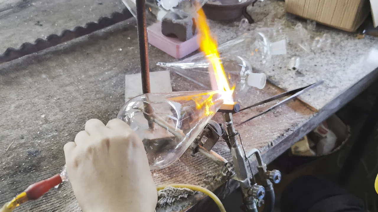
Select the Workstation Around the Forming Sequence
Consider how the component changes during manufacture. A straight tube may become a branched assembly whose rotation, support and transfer needs differ substantially from those of the starting stock.
Swipe horizontally to view all columns.
| Arrangement | Reasons to consider it | Main setup questions |
|---|---|---|
| Bench burner with hand-held glass | Local forming and features needing frequent repositioning | Can the operator handle the weight and reach the working region consistently? |
| Supported assembly with a hand torch | Joints or attachments on parts that are difficult to rotate | Is support stable, with access around the joint and protection for adjacent features? |
| Glassworking lathe | Rotational forming, axial joining and support of longer components | Are holding capacity, alignment, axial travel and burner access suitable? |
| Combined arrangements | Parts requiring both rotational forming and separate attachments | How will the component be transferred and its orientation recovered? |
A glassworking lathe supports and rotates glass during forming; the heated material is redistributed rather than machined away.[1] Its presence alone does not establish a finished tolerance. Compare the lathe's clear bore, distance between holding points, radial clearance, burner travel and chuck arrangement with the complete part sequence.[2]
Review loading, every intermediate shape, inspection access and unloading. Reserve space for hoses, tools and temporary holding sections. Identify which features establish position when the part moves between setups. For detailed component and interface requirements, use the lampworking design guide alongside the equipment review.
Match Torch Coverage to the Working Region
Select heating coverage for the amount and distribution of glass involved. A narrow joint, thick attachment and broad hollow body need different access and heat distribution. Nearby finished features may restrict the usable flame direction.
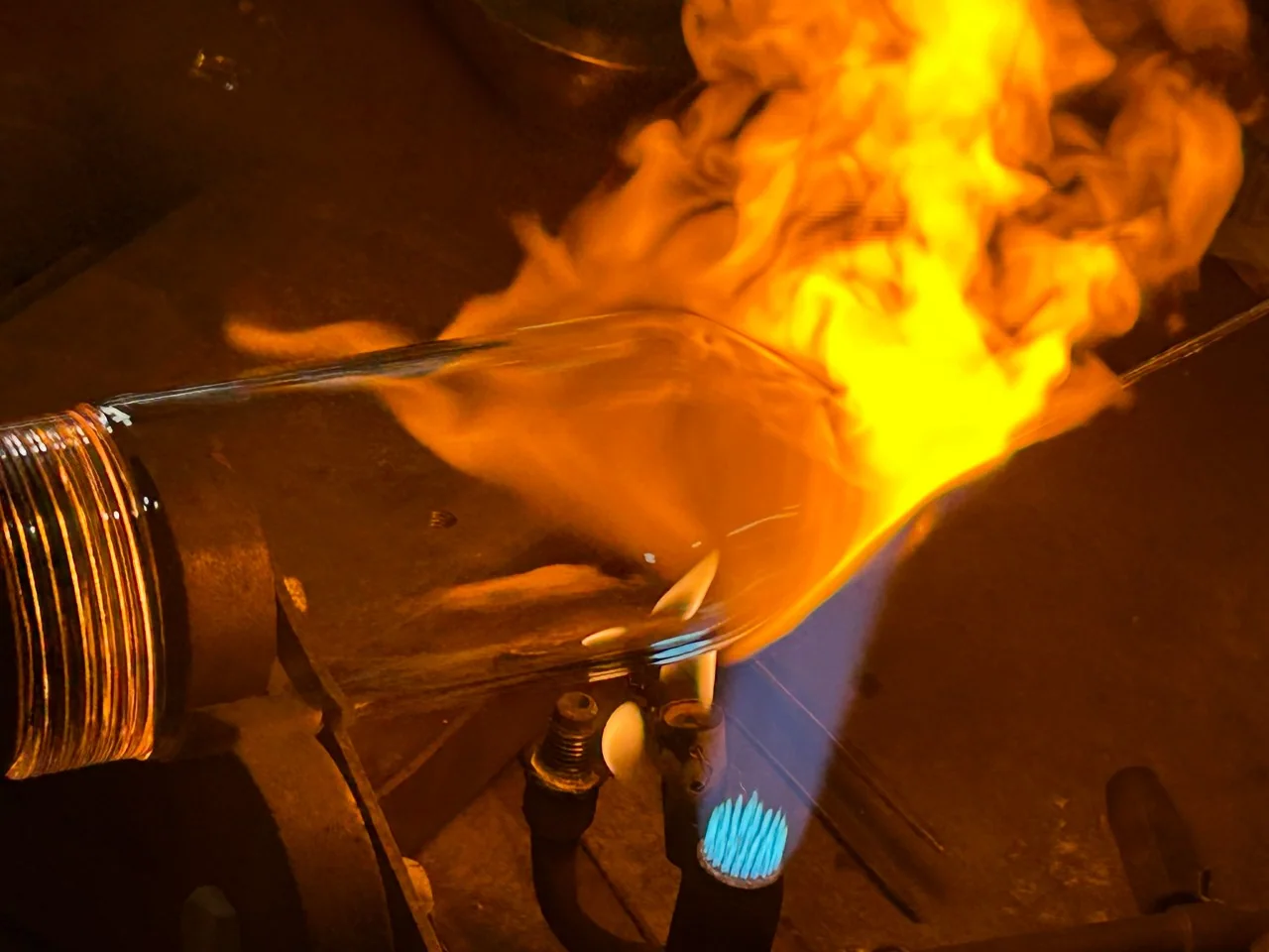
Surface-mix burners keep fuel and oxygen separate until the burner face; premix designs combine them upstream of the flame outlet. Follow the operating limits and protective arrangements for the particular equipment. A burner category is not enough information to specify its installation.
Some burners provide separately controlled inner and outer stages. This can change the heating area, but the available operating range and required supply depend on the model and active stages.[3]
Evaluate access to the whole forming region, coverage at the intended working position, clearance from supports and stable operation across the required range. High nominal output does not prove that a joint can be heated evenly.
Use representative stock to establish the arrangement. Record the burner, installed tip or nozzle, active stages and mounting position. Account for heat reaching adjacent glass and fixtures. If the layout forces awkward positioning or leaves part of a joint inaccessible, revise the support or operation sequence before treating burner adjustment as the solution.
Confirm Gas Delivery Under Operating Demand
Confirm the permitted fuel, oxygen source, pressure and flow requirements from the selected equipment's instructions. Assess the complete delivery system, including regulators, hoses, connections, valves and protective devices.[4]
Pressure and flow describe different conditions. A pressure reading at an idle station does not demonstrate delivery while the burner operates. Identify the measurement point and operating state, using instruments and checks suitable for the installation.
Swipe horizontally to view all columns.
| Delivery characteristic | What to establish |
|---|---|
| Gas identity | Permitted fuel and oxygen source for the installed burner |
| Pressure under demand | Measurement point, units and active burner configuration |
| Flow, where measured | Gas, instrument suitability and reference conditions |
| Oxygen concentration | Source specification and verification appropriate to its use |
| Shared demand | Stations and burner stages operating together |
| Changeover | How cylinder or source changes affect stable delivery |
For concentrator supplies, assess oxygen concentration, flow and delivery pressure together. Suitability can differ between a burner operating on its inner flame and the same burner with additional stages active.[5]
Verify shared supplies under the expected simultaneous demand. Investigate unexpected flame changes before compensating through forming technique. Delivery restrictions, source condition or an equipment fault may require attention rather than a new production setting.
Choose Forming Tools and Plan Their Removal
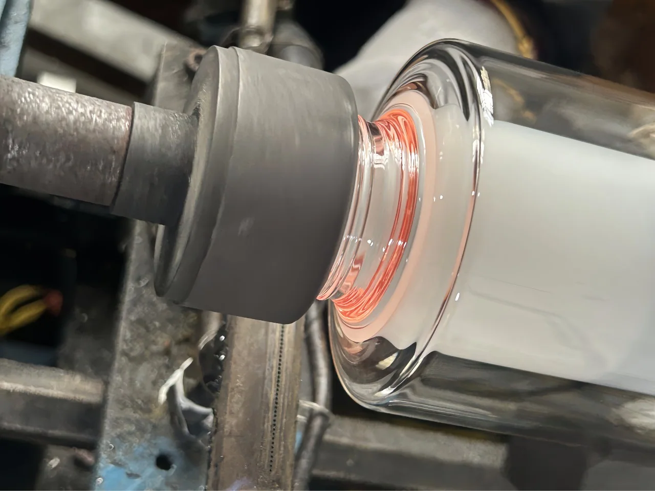
Select tools for their contact geometry, material, surface condition and access at the intended production stage.
Swipe horizontally to view all columns.
| Tool group | Main function | Characteristics to control |
|---|---|---|
| Paddles and marvers | Shape or support external surfaces | Profile, flatness, contact area and surface condition |
| Reamers and flaring tools | Develop openings and internal transitions | Taper, working diameter, insertion access and finish |
| Mandrels and internal formers | Guide a bore, curve or repeated internal feature | Geometry, alignment, release and removal path |
| Jacks and shaping tools | Develop necks, grooves and local profiles | Contact shape, spacing, symmetry and clearance |
| Handling and dedicated tools | Position features or reproduce a particular shape | Grip location, reach, drawing revision and wear limits |
Graphite, suitable metals and selected ceramics serve different tooling functions. Assess heat exposure, contact behaviour, wear and contamination for the actual application. Specify any approved coating or release material and review its effect on the surface and workplace emissions.
A mandrel must be removable after the planned forming stage. Check its withdrawal direction, available opening, tool supports and clearance from features added later. An undercut or subsequent closure can trap an otherwise suitable former. Where a multipart tool is proposed, define its assembly and removal sequence.
Do not assume cooling will release a tool: contact and differential thermal movement need assessment for the material combination. Verify removal on representative trials without forcing the glass. Inspect contact surfaces for damaged edges, embedded particles and worn profiles that could mark the part or change its geometry.
Hold and Support the Glass Without Overconstraint
Place holding contacts where they can support the work without damaging functional surfaces or restricting the intended forming region. Account for the stock's weight, unsupported length and the added mass of attachments. Base holders and supports on the agreed incoming dimensions and variation, as described in the tube and rod selection guide.
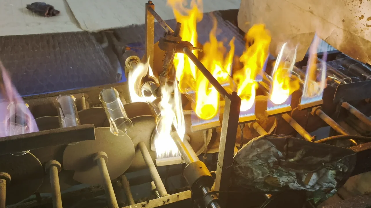
Specify the relevant chuck, jaw, collet, roller or fixture configuration. Select contact materials for the expected heat, cleanliness and grip requirements. Thin walls and uneven profiles may respond differently to the same holding arrangement, so verify secure support on representative stock.
Avoid assuming that greater clamping force improves stability. Excessive or uneven contact can damage glass, while inadequate support permits movement. Establish a suitable holding method through the equipment instructions and trials, rather than assigning one clamping condition to every size.
Allow for the axial movement needed during joining and for changes in length as the work heats and cools. Review support at each stage so the assembly is neither unintentionally restrained nor left unsupported when a tool or holding section is removed.
Long branches, handles and offset features may need temporary support. Define where that support contacts the component, when it is adjusted and how it is removed. Verify unloading as carefully as loading; a completed feature may obstruct the original exit path.
Establish Alignment, Rotation and Clearance
Define the axis or reference feature used to position the glass. Aligning fixture centres does not establish the position of an uneven tube bore or guarantee the final component's geometry.
For axial joints, check the relationship between the held parts at the intended joining region. Specify how offset, angular alignment and the required gap or overlap are assessed. Keep setup alignment requirements separate from finished-part runout or concentricity requirements on the drawing.
Where both ends are driven, use the machine's approved arrangement for coordinated rotation and axial movement. Rotation settings must suit the equipment, geometry, support and forming response; there is no universal speed for borosilicate lampworking.
Review the swept envelope of the largest intermediate and finished shape. Include branches, attached tools, fixture projections, burners and hoses. Use the equipment's approved clearance-checking procedure before introducing heat, and repeat the review when a new attachment changes the envelope.
Unexpected movement, vibration or loss of alignment calls for a setup review. Check the stock, holding contacts, support and machine condition before adjusting the forming operation. A visually steady rotation alone does not demonstrate that the required reference features are aligned.
Plan Hot Transfers and Dimensional Checks
Provide defined locations for incoming stock, active work, hot tools and parts awaiting transfer. The receiving support and available annealing space should be ready for the intended production sequence.
Plan who supports the component and where it is contacted during transfer. Account for slender necks, projecting branches and areas that remain susceptible to deformation. A convenient grip during forming may be unsuitable for carrying the completed assembly.
Keep precision measuring equipment and accepted parts away from unnecessary heat exposure. Distinguish observations used to guide forming from measurements used to accept the finished component.
If an in-process gauge contacts warm glass, establish its suitability, contact location and effect on the surface. Do not assume a hot dimension equals the cooled dimension. Final acceptance should specify the component condition, reference features and measuring method after the required annealing and finishing operations.
Maintain access to the critical features. Where a joint or internal region will become inaccessible, decide what needs checking before closure and what evidence must still be confirmed on the completed part.
Integrate Gas Safety, Extraction and Eye Protection
Have the installed gas system assessed by personnel competent in the equipment and gases involved. Use suitable regulators, connections and hoses; protect oxygen-service components from oil, grease and incompatible materials. Provide identifiable circuits, accessible isolation and hose routing clear of hot surfaces and moving equipment.
Determine non-return valves and flashback protection from the complete installation, manufacturer instructions and applicable requirements. A non-return valve and a flashback arrester perform different functions. Use a suitable approved leak-detection method; never use a flame to find leaks. General oxy-fuel guidance supports these principles, while the actual burner instructions govern its operation.[6]
Document startup, shutdown and abnormal-condition responses for the installed equipment. Follow those instructions rather than transferring a sequence from another burner or process.
Capture emissions across the working area
Assess combustion products and substances released by the glass, coatings or other materials used. Design and commission local exhaust ventilation for representative burner positions and workpieces. Capture depends on the hood arrangement, airflow, replacement air and how the process is operated.[7]
A large body or fixture may obstruct capture. Review extraction when the layout, materials or operating demand changes. Verify performance through the agreed checks; visible flame behaviour alone does not demonstrate effective extraction.
Select protection while preserving visibility
Sodium-flare filtering improves visibility but does not, by itself, establish protection against all relevant ultraviolet, infrared or impact exposure. Select complete eyewear for the glass type, working scale and workplace assessment, with supplier confirmation of suitability.[8]
Review fit, side coverage, lens condition and exposure at neighbouring stations. Select other personal protection for the assessed hazards and equipment. Arrange lighting and backgrounds to reveal tool contact and the glass profile. Because protective filters affect perceived colour, assess final colour under the specified inspection conditions.
Verify the Setup with Representative Workpieces
Qualify the arrangement against the parts it must produce. Include the relevant extremes of diameter, wall, length, joint position and added features; the largest outside dimension alone may not represent the most demanding operation.
Swipe horizontally to view all columns.
| Verification stage | Check | Evidence to retain |
|---|---|---|
| Before hot work | Holding, tool access, removal paths, clearance and transfer arrangements | Approved configuration and resolved access issues |
| Representative forming | Heating coverage, supply stability, support and rotation through the sequence | Trial observations linked to stock and setup |
| After annealing and finishing | Required dimensions, joint condition, appearance and agreed acceptance checks | Finished trial results and disposition |
| Before repeat production | Equipment condition, material identity and approved setup configuration | Release record and identified changes |
Assess production practicality as well as the first successful piece. Check whether loading, forming, removal and transfer can be repeated without progressive tool contamination, fixture movement or unresolved heating variation.
Record unsuccessful trials and the cause of each change where known. Accept the setup against defined finished-part requirements, not solely a stable-looking flame or an apparently smooth joint. Agree any remaining qualification work before releasing the arrangement for the intended production scope.
Maintain the Setup for Repeat Production
Record equipment identity, fixture and tool revisions, holding locations, burner configuration and relevant positions. Include the supply conditions, rotation settings where applicable, process sequence and inspection references established during verification.
Use photographs or drawings where they clarify orientation and access, while retaining measurable settings and reference features. A photograph alone may not reproduce a critical position.
Inspect burner, supply and protective equipment according to their instructions. Maintain forming surfaces, supports, holding contacts and measuring equipment at intervals appropriate to use. Define the condition requiring cleaning, service, refurbishment or replacement; worn tooling should not silently become the new production reference.
Review changes that could affect the result, including stock size, glass grade, burner tip, gas source, fixture, tool material or extraction layout. Recheck the affected safety and process functions, and repeat representative trials where the established acceptance evidence no longer applies.
For setup review and quotation, provide BO-Glass with the drawing, application, glass details, quantities and critical acceptance requirements so heating, tooling and support can be planned together.
References
- Adams & Chittenden Scientific Glass — Scientific Glassblowing.
- Litton Engineering Laboratories — U-11 Glassworking Lathe Specifications.
- Bethlehem Burners — Bravo Operating Instructions.
- Bethlehem Burners — Technical Information.
- Bethlehem Burners — Oxygen Concentrators.
- Health and Safety Executive — Safety in Gas Welding, Cutting and Similar Processes. General oxy-fuel safety principles; use equipment-specific instructions for lampworking operation.
- Health and Safety Executive — Controlling Airborne Contaminants at Work: A Guide to Local Exhaust Ventilation (LEV).
- Phillips Safety — What Glasses Do I Need to Wear for Lampworking with Borosilicate Glass?
Contact Us
Your feedback fuels our growth, and your questions drive our solutions.
We value your feedback, inquiries, and suggestions. Please feel free to get in touch with us
General inquiries
Please contact us via sales@bo-glass.com, and we will reply to you as soon as possible.
Interested to work with us
Drop your resume at info@bo-glass.com
and we will get back to you shortly.
Request a Custom Glass Quote
Tell us about your project or upload a drawing.
Your drawings remain confidential.
We uses the contact information you provide to us to contact you about our relevent content, products, and services.