
← Back to the glass rod pressing technology guide
Thermal Cycle, Cooling and Optical Performance Validation
A precision-moulded glass component reaches its final condition through the complete thermal cycle. Geometry can change as the glass and tooling cool, while the glass's internal structure and stress state influence its optical behaviour.
This companion to the Precision Glass Moulding Design Guide covers controlled cooling, any additional thermal treatment, and validation of the finished component. Machine-control modes and stage-transition logic are covered in Precision Glass Moulding Process Control.
At a glance: Connect thermal history with measurements at the agreed acceptance state. Surface form, birefringence, wavefront and functional tests answer different questions. Separate annealing is not automatically required, and an improvement in one result must not compromise another requirement.
Define the Thermal and Optical Acceptance Criteria
Thermal-cycle development begins with the product requirements and the condition in which the component will be accepted.
A component may have acceptable dimensions but an unsuitable stress distribution. A lens may reproduce the specified surface geometry while its focal performance differs from the design because of refractive-index variation. These outcomes require different measurements.
Select the critical characteristics, measurement methods and acceptance limits for the intended application; not every component needs every test below.
| Characteristic | What is evaluated | Conditions to specify |
|---|---|---|
| Surface form | Departure from the nominal optical surface | Evaluation aperture, nominal surface definition, fitting terms, filtering and reported metric |
| Dimensions and alignment | Thickness, outside geometry, wedge and optical-to-mechanical relationships | Datums, part temperature, fixture and measurement method |
| Stress birefringence | Optical retardation associated with the stress state | Wavelength, light path, measurement area, orientation and reporting units |
| Refractive index and dispersion | Material optical properties after the relevant thermal history | Wavelengths, temperature, reference condition and validation method |
| Transmitted wavefront | Combined optical-path deviation through the component | Wavelength, pupil, reference wavefront, test configuration and mounting condition |
| Focal and imaging performance | Optical power, focal position and contrast transfer | Conjugates, aperture, field position, wavelength and focus convention |
| Illumination performance | Beam distribution, uniformity or collected optical output | Source characteristics, source position, detector geometry and operating condition |
| Spectral transmission | Light transmitted through the finished component | Wavelength range, path length, angle, polarisation, coating state and collection geometry |
The specification should also identify whether acceptance applies to the stabilised moulded part, a separately annealed component, the coated delivery item or an assembled optical unit. Results obtained at these different stages should remain identifiable.
For each selected characteristic, identify whether verification is required during development, by production lot, on individual parts or after a relevant change. Define sampling in the control plan rather than treating this guide as a universal inspection schedule.
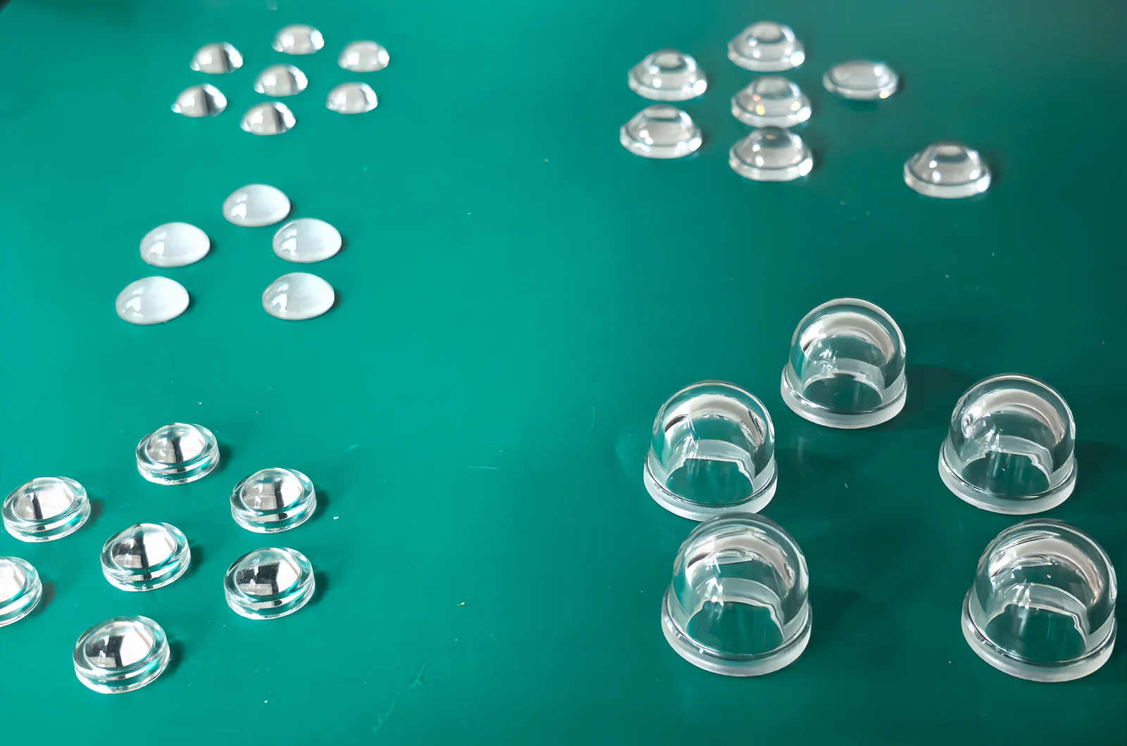
Understand How Thermal History Changes Moulded Glass
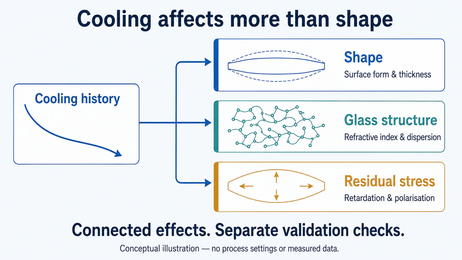
The thermal cycle influences the component through three connected mechanisms.
Geometry changes occur as the glass and mould expand, contract and interact. Deformation may continue while the glass can flow, and restraint or contact changes can affect the final surface profile.
Structural relaxation describes how the internal glass structure adjusts towards the condition associated with its temperature. The rate of this adjustment changes strongly with temperature. Different cooling histories can therefore leave glass with different room-temperature structural states.
Mechanical stress develops when different regions or contacting materials cannot expand or contract freely together. Some stress is temporary and disappears when temperature differences vanish. Other stress remains after thermal equalisation.
Shape deviation, refractive-index change and birefringence can have related thermal causes, but they are not interchangeable measurements. Research on precision glass moulding identifies cooling history as a contributor to final profile deviation and residual stress. Liu and Zhang (2015): Thermoforming mechanism of precision glass moulding
Establish the Cooling Profile for the Glass and Geometry
A cooling profile must suit the glass, component dimensions, tooling arrangement and required optical condition.
The same machine programme can produce different temperature distributions in components with different thicknesses or contact areas. Upper and lower mould temperatures may also differ from the temperature inside the glass.
Understand the Relevant Temperature References
Tg, the annealing point and the strain point describe different aspects of glass behaviour.
- Glass transition temperature, Tg, characterises transformation behaviour under specified measurement conditions.
- Annealing point is a viscosity-based reference associated with stress relaxation over a defined timescale.
- Strain point is a lower-temperature reference where stress relaxation is much slower.
These references guide development; they do not define a complete recipe or a sharp temperature below which every relevant change stops. SCHOTT TIE-31: Mechanical and thermal properties of optical glass
Use Cooling Stages with Defined Purposes
A practical cooling programme may use different rates and restraint conditions through different temperature regions.
| Cooling region or event | Main consideration |
|---|---|
| Early cooling while the glass remains deformable | Continued shape change, contact conditions and applied restraint |
| Cooling through the region where relaxation remains significant | Temperature distribution, structural relaxation and residual-stress development |
| Later cooling after relaxation becomes slow | Temporary thermal stress, dimensional contraction and handling readiness |
| Unloading and release | Glass–mould adhesion, differential contraction and mechanical damage |
A lower cooling rate can reduce relevant temperature gradients in some conditions, but its effect must be demonstrated for the actual component. Extending the cycle also changes tooling exposure, throughput and potentially the glass–mould interaction.
Faster cooling at lower temperatures may be practical after the critical relaxation region has been passed. It still requires evaluation because temporary thermal gradients can cause damage even when little permanent stress relaxation occurs.
Record the Meaning of the Cooling Rate
A reported cooling rate needs an identified temperature interval and measurement location.
An average rate over the full cycle can conceal a rapid change within a sensitive region. The programmed ramp may also differ from the measured mould-temperature slope and from the cooling rate inside the glass.
Record the relevant temperature traces, stage boundaries and load-release events. Where glass temperature is inferred from modelling, identify the assumptions and how the prediction was checked against the process.
Coordinate Cooling, Mould Restraint and Release
Differential thermal contraction, friction and adhesion affect the loads acting on the cooling component. Define the restraint changes, unloading criteria, release sequence and handling conditions within the qualified machine programme described in Precision Glass Moulding Process Control.
Loss of contact can change local heat transfer. A thermal model that assumes continuous contact may need revision if the actual component separates from part of the mould during cooling.
For asymmetric optics or uneven thickness, evaluate whether different regions cool or release at different times. Compare post-release geometry, edge condition and release marks with the corresponding thermal and mechanical records.
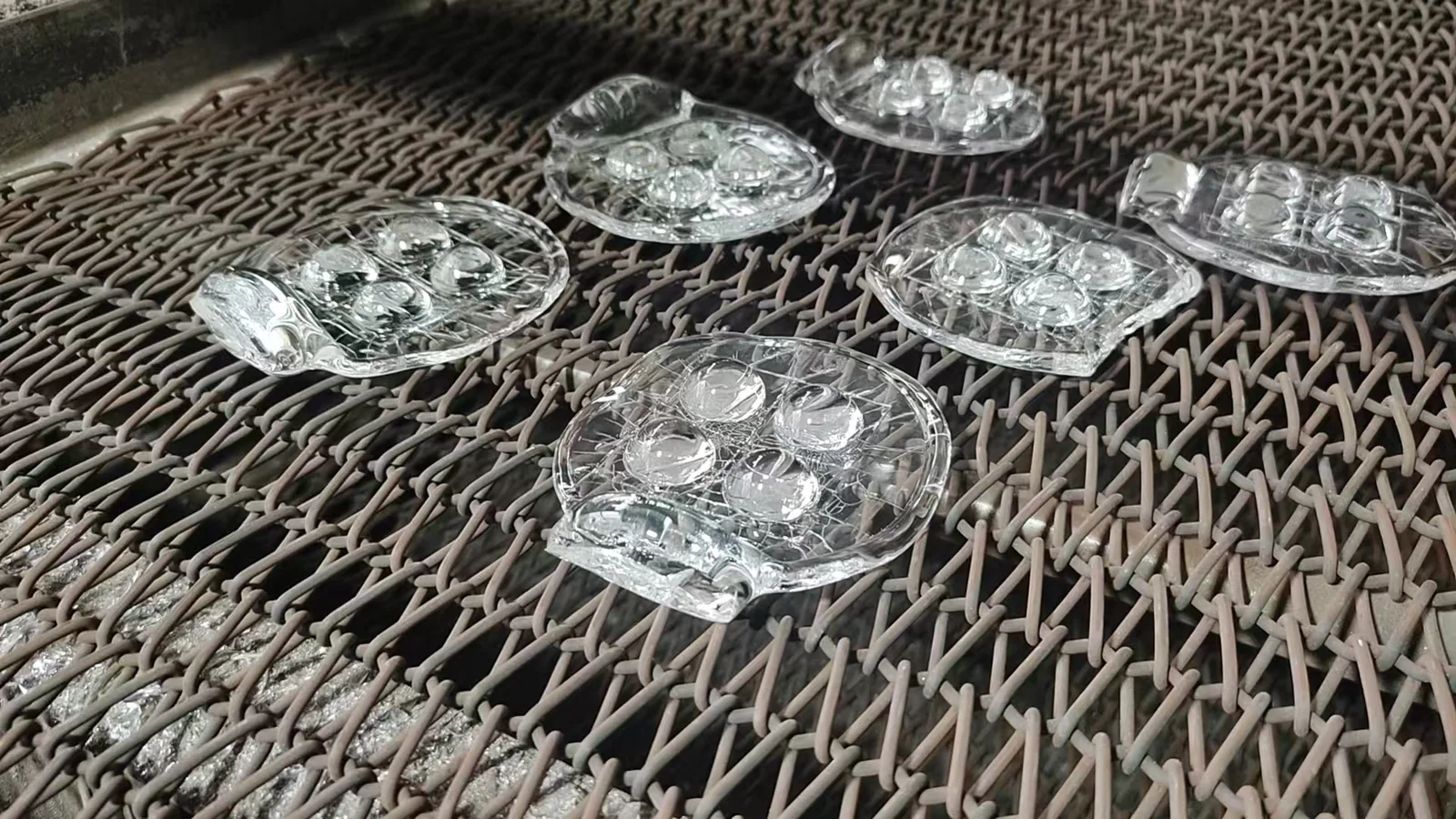
Determine Whether Separate Annealing Is Required
Separate annealing should address a defined stress or structural requirement that the moulding cycle does not adequately meet. Assess the intended improvement together with its effects on geometry, surface quality and optical properties.
Reheating can allow relaxation, but it can also change precision optical surfaces and refractive index. SCHOTT TIE-31: Mechanical and thermal properties of optical glass
| Current validation result | Appropriate evaluation direction |
|---|---|
| The moulding cycle meets all critical requirements | Confirm repeatability and the applicable production range; additional annealing is not automatically needed |
| Stress-related requirements are not met | Verify the measurement and fixture conditions, then assess changes to the moulding cycle or an additional treatment |
| Annealing improves stress-related results but causes unacceptable form or focal performance | Reassess the treatment; the stress improvement alone does not support release |
Define the temperature and time programme, support arrangement, contamination controls and before-and-after measurements. Review compatibility with existing coatings and subsequent processing.
An additional treatment must achieve its intended improvement while preserving every other applicable acceptance requirement.
Annealing should not be treated as a general repair method for cracks, mould damage, contamination or incorrect component geometry.
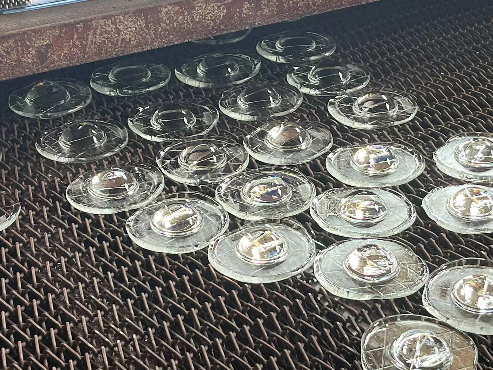
Account for Refractive-Index and Dispersion Changes
The optical properties used in a lens design must represent the relevant material condition.
Glass catalogues and material certificates may state refractive index under a defined reference annealing condition. The moulded component can experience a different thermal history.
For the precision-moulding glasses discussed in SCHOTT's guidance, faster cooling than the catalogue reference treatment can produce a lower refractive index, commonly described as an index drop. Dispersion can also change. The magnitude depends on the glass and thermal history; a universal correction should not be assumed. SCHOTT TIE-40: Optical glass for precision molding
Three effects deserve separate consideration:
- A change in average refractive index, which can alter optical power.
- Spatial refractive-index variation, which can affect the optical path across the component.
- Stress-induced birefringence, which produces different behaviour for different polarisation directions.
Interferometric reconstruction has been used to investigate refractive-index and dispersion distributions after different thermal histories; one nominal material value may not describe the complete optical state. Applied Optics (2009): Refractive index and dispersion variation in precision optical glass molding by computed tomography
Identify the Validation Basis
Material documentation, representative measurements, component tests and models provide different evidence.
| Validation basis | What it can establish | Boundary to document |
|---|---|---|
| Material or melt certificate | Material properties under the stated reference or supply condition | It does not automatically establish the optical state after moulding |
| Representative-sample measurement | Properties associated with the sample’s material and thermal history | Its relationship to the actual component must be demonstrated |
| Finished-component optical testing | Compliance with specified focal, wavefront or other functional requirements | A focal or wavefront result alone does not uniquely determine refractive index |
| Model correlated with measurements | Support for prediction, design compensation and process assessment | Applicable materials, geometries, process conditions and prediction limitations must be identified |
A witness sample is not automatically representative because it entered the same furnace or machine. Its dimensions, contact conditions and cooling behaviour matter.
A focal-length deviation should not be attributed to refractive index before surface geometry, thickness, alignment and test conditions have been checked.
Stabilise Components and Set Common Measurement Conditions
A recently demoulded part may still contain temperature gradients that influence dimensions, optical path and stress response. Define the ambient conditions, stabilisation method and temperature criterion for inspection. Temperature checks or repeated measurements can support stabilisation; there is no universal waiting period for every geometry and tolerance.
Room-temperature waiting allows thermal equalisation. It generally does not remove residual stress retained from the high-temperature cooling history.
Handling and fixtures must avoid contamination, damage and unintended mounting stress. Represent the agreed acceptance state: unmounted component or defined assembly.
Use a Common Measurement Record
For the methods below, record part and lot identity, processing state and the applicable thermal-history reference. Establish these common conditions once in the inspection plan:
- Measurement temperature, stabilisation, orientation, datums and fixture or preload.
- Wavelength or spectral weighting, where relevant, and evaluated aperture or locations.
- Instrument and method, analysis settings, reported quantity and units.
- Measurement uncertainty and repeatability, including repositioning where relevant, together with the acceptance limit and decision rule.
Instrument resolution alone does not demonstrate suitability for a tolerance. Define how uncertainty and borderline results are handled before acceptance testing; do not change the decision rule after seeing the result. Each method also needs the specific conditions described below.
Validate Dimensions and Optical Surface Geometry
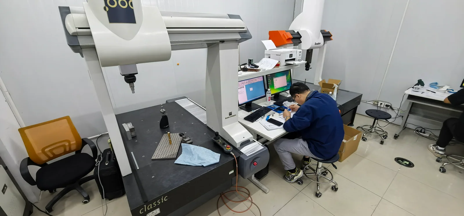
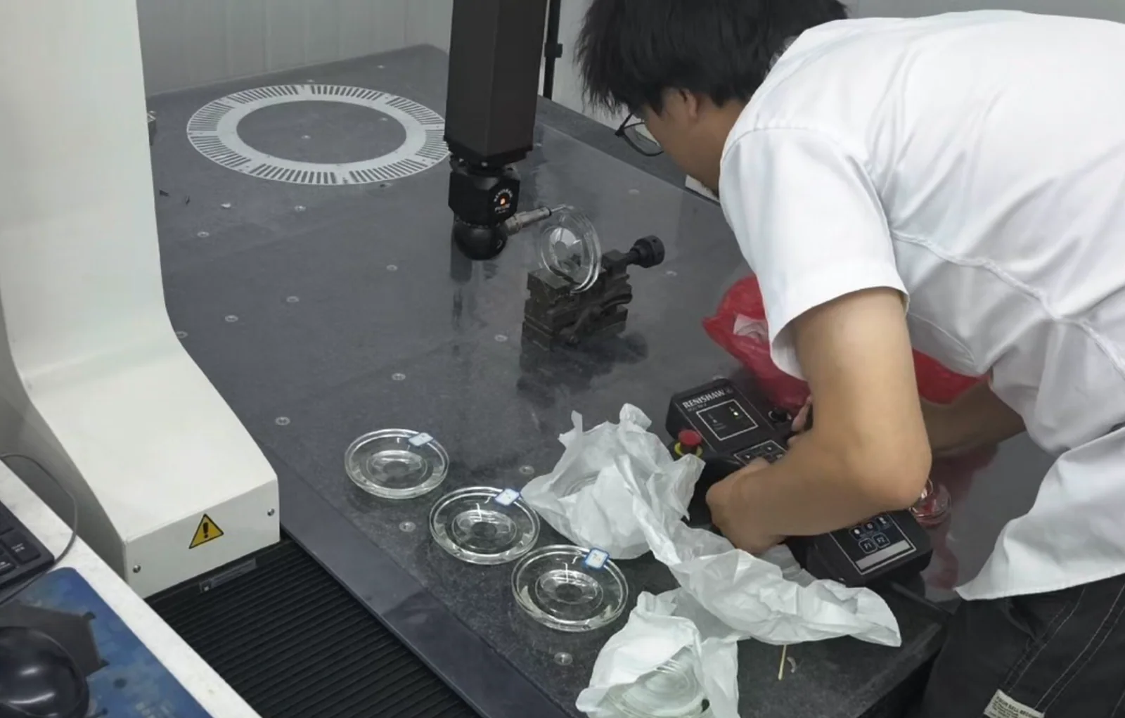
Check the specified thicknesses, outside dimensions, wedge, centration and optical-to-mechanical relationships. For freeforms, retain the prescribed coordinate system and orientation.
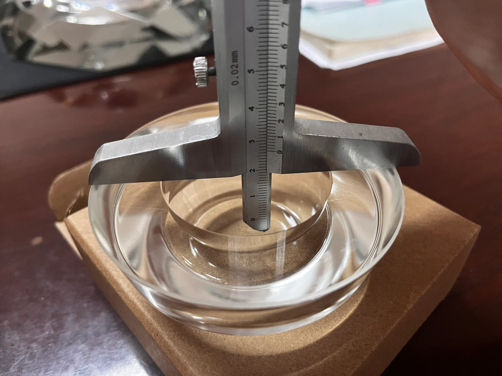
Compare Surface Form with the Correct Nominal Geometry
In addition to the common measurement record, identify:
- The nominal sphere, asphere or freeform, and the alignment method.
- Fitted or removed terms, spatial filtering and excluded data.
- The surface-error metric and whether it describes absolute geometry or fitted residuals.
Peak-to-valley, or PV, reports the range between the highest and lowest deviations in the evaluated data. RMS describes the overall magnitude of the residual deviations. Both depend on how the surface is fitted and which data are included.
Removing a best-fit radius or power term can conceal a radius-related manufacturing deviation if that term is part of the acceptance requirement. The report should distinguish absolute geometry from residual irregularity after the agreed fitting operation.
Surface-height error and optical wavefront error must also be identified separately. If a result is reported in waves, state the wavelength and measurement convention.
Match the Measurement Method to the Surface
Steep aspheres and freeforms may require a suitable null, computer-generated hologram, stitching method or an alternative to interferometry, such as appropriate profilometry. Verify coverage and uncertainty for the specified surface.
A single measured profile cannot establish the condition of an entire asymmetric surface.
Surface roughness, waviness and overall form describe different spatial features. A roughness result needs an identified measurement area or length, filtering and metric. It should not be used as a substitute for optical surface-form validation.
Measure Stress Birefringence and Interpret Residual Stress
Mechanical stress can make optical glass behave differently for different polarisation directions. This produces birefringence and an optical-path difference, commonly reported as retardation.
The relationship to mechanical stress depends on the glass's stress-optical properties, wavelength, optical path and stress distribution. A retardation map does not automatically provide a complete internal mechanical-stress distribution. SCHOTT TIE-27: Stress in optical glass
Distinguish the Reported Quantities
- Retardation, in nm: the optical-path difference accumulated along the measurement path.
- Retardation per unit path length, such as nm/cm: retardation normalised using an identified light-path length.
- Birefringence, Δn: the dimensionless difference between refractive indices for the relevant polarisation directions.
- Mechanical stress, such as MPa: a mechanical quantity requiring an appropriate relationship between optical measurements, material properties and stress state.
These quantities cannot be treated as interchangeable labels.
Curved surfaces can complicate the optical path and measurement geometry. Conversion to mechanical stress requires a suitable stress-optical model and material data, with the interpretation limited to what the method can resolve.
Distinguish Visual Screening from Quantitative Acceptance
Viewing a component between crossed polarisers can reveal patterns useful for screening and investigation.
Appearance depends on orientation, optical path and observation sensitivity. A dark image alone does not establish that every relevant stress component is zero.
Use a suitable quantitative method for numerical acceptance rather than interpreting colours alone. Hinds Instruments: Residual stress birefringence in optical materials
Define the Measurement and Reporting Conditions
Apply the common record and decision rule. Additionally, identify the light path used for any normalisation, measured retardation and orientation where available, and any stress-optical coefficient or model used to report mechanical stress. State the limits of that interpretation, particularly for curved parts and nonuniform stress fields.
Validate the Transmitted Wavefront
Transmitted-wavefront measurement evaluates optical-path variation through the component.
It can include contributions from both optical surfaces, wedge and refractive-index inhomogeneity, providing information beyond an individual surface-form measurement. ZYGO: Transmitted wavefront
The result must be referenced to the intended wavefront for the test configuration. A lens that intentionally focuses light should be evaluated against the appropriate nominal converging or diverging wavefront.
Alongside the common conditions, specify the reference wavefront and optical configuration, single-pass or double-pass arrangement, fitted or removed terms, filtering, and reported PV, RMS or other agreed metrics.
Raw results from different pass configurations should not be compared without the appropriate interpretation.
Focus removal also needs attention. A lens can show acceptable wavefront quality at its measured best focus while its focal position differs from the design. Focal-position requirements should therefore be checked separately when relevant.
When transmitted wavefront fails, compare it with surface-form, thickness, alignment and material information. The wavefront result alone does not isolate the contribution responsible for the deviation.
Verify Focal, Imaging and Illumination Performance
Functional testing should represent what the component is intended to do.
Focal Length and Focal Position
Effective focal length and back focal length describe different distances.
Effective focal length is referenced to the optical system's principal planes. TRIOPTICS: Focal length measurement Back focal length uses the rear surface vertex as its reference for the relevant collimated-input condition. Schneider-Kreuznach: How to read an optical data sheet
Identify the distance reference as well as the common test conditions; this distinction matters for assembly spacing and optical power.
If the glass’s refractive index changes after moulding, focal performance may change even when the surface geometry remains close to nominal. The investigation should consider material and geometry together.
Imaging Performance and MTF
The modulation transfer function, or MTF, describes how an imaging system transfers contrast at different spatial frequencies.
Match the intended object and image conjugates; an unsuitable conjugate tests a different optical condition from the design. Optikos: MTF measurement at proper conjugates
Identify field position, spatial-frequency units and whether frequencies refer to object or image space. Label sagittal and tangential results where relevant.
State whether all field points are evaluated at a common image plane or at independently optimised focus positions. Define the focus criterion and relevant spatial frequencies; different criteria can give different best-focus planes. For acceptance in a flat-detector system, use the focus convention required by that system rather than silently refocusing each field. Optikos: Finding Focus
An individual lens should be compared with its component-level requirement. Its measurement does not independently establish the performance of a complete camera or optical assembly.
Illumination and Beam-Shaping Performance
Illumination optics may require beam-distribution, uniformity, focal-spot or collected-output measurements.
Define the source's emitting geometry, spectrum, position and operating condition, together with detector geometry. For an LED optic, use an agreed LED or representative source: a changed emitting area or position can alter the measured beam even when the glass is unchanged.
Check Spectral Transmission and Surface Quality
A visually clear component does not independently establish the required spectral transmission.
Material absorption, optical path length, surface reflection, coatings and scattering can all influence the measured result.
Internal transmittance excludes surface-reflection losses and should be distinguished from transmission through the finished component. SCHOTT TIE-35: Transmittance of optical glass
Alongside the common spectral conditions, identify the path length, incidence angle, polarisation where applicable and coating state.
Collection geometry also matters. A measurement that collects scattered light may produce a different result from one limited to the directly transmitted beam.
Surface inspection should address the specified cosmetic and functional conditions, including relevant marks, scratches, pits, haze or contamination.
Investigate treatment-related changes using before-and-after measurements under equivalent conditions.
Verify Performance After Coating, Mounting and Thermal Exposure
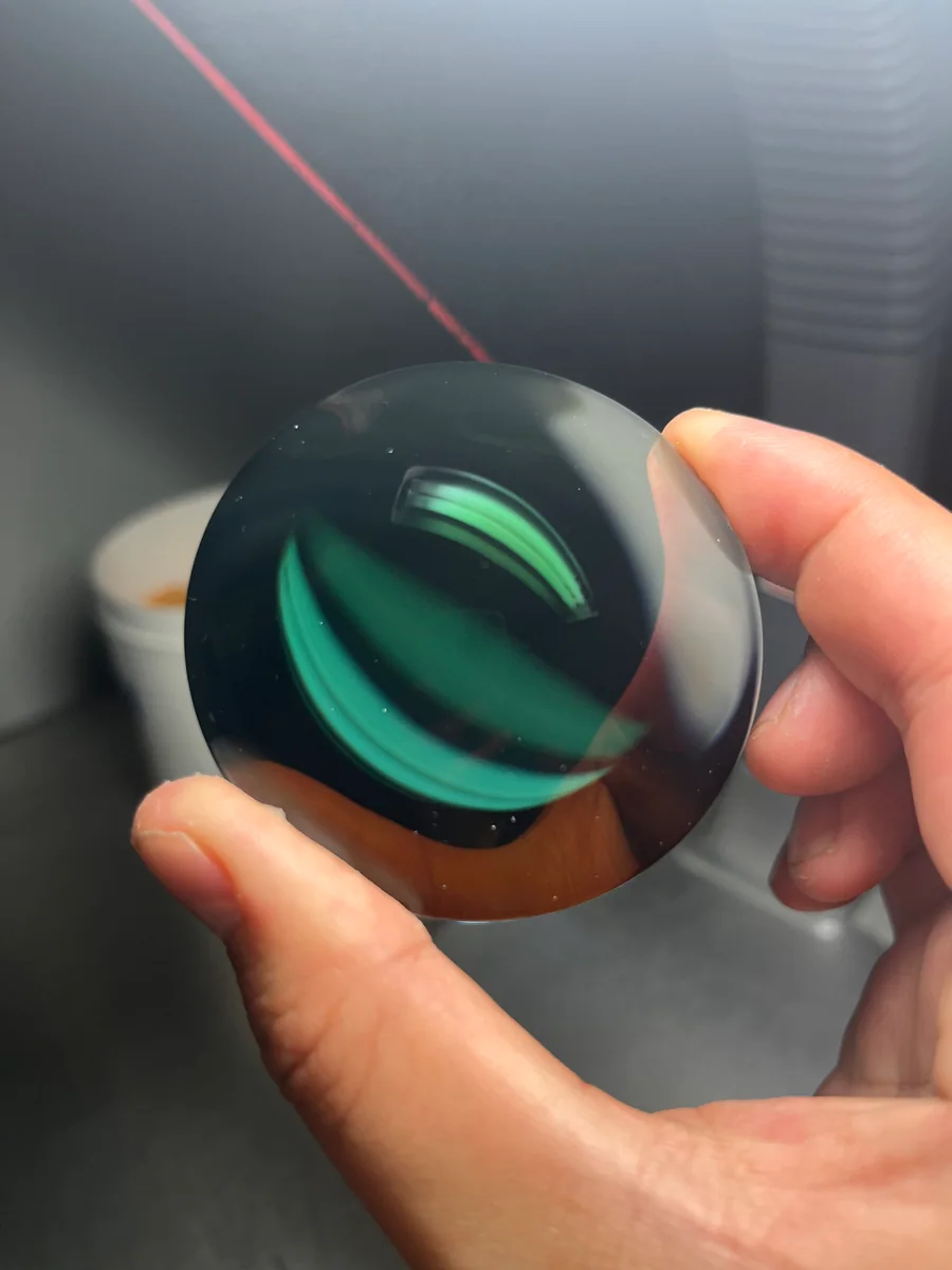
Coating deposition, edge processing, adhesive curing and mounting can introduce further thermal or mechanical effects. Identify the operations that could affect critical requirements and confirm performance at the acceptance state defined at the start of this guide. Intermediate checks do not replace that final assessment.
Distinguish Operating-Temperature Tests from Post-Exposure Tests
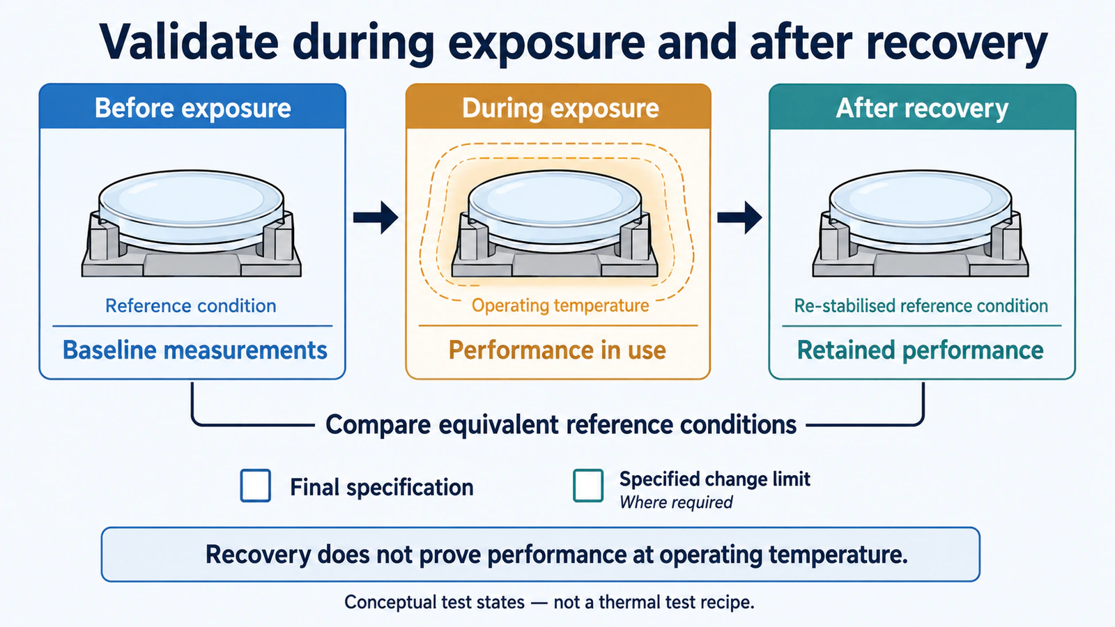
Performance measured at an operating temperature and performance measured after thermal exposure answer different questions. Specify whether the component must work within limits while hot or cold, retain its performance after returning to a reference temperature, or satisfy both requirements.
Define the temperature range, ramp rates, dwell criteria, number of cycles, mounting or preload, and the required measurements for the application. State whether a dwell starts when the chamber reaches its setting or when the component meets a defined temperature criterion. There is no universal thermal-exposure schedule for all moulded optics.
For post-exposure comparison, re-stabilise the part at the same reference condition used for the baseline. For measurements during exposure, record the actual test condition and use a method suitable for that temperature. Do not treat recovery at room temperature as proof of optical performance throughout the operating range.
Evaluate Final Results and Changes Separately
Where practical, use the same component for non-destructive before-and-after measurements of form, wavefront, birefringence or focal position. Maintain equivalent reference conditions and analysis settings so that part-to-part variation or a changed test method does not obscure the effect.
Two separate acceptance questions may apply:
- Does the final result meet its absolute specification?
- Where a change limit has been specified, does the measured change remain within that limit under equivalent test conditions?
A small measured change does not establish conformity; the final result must also meet its absolute specification. Equally, a final value within its absolute specification does not excuse exceeding a separately agreed change limit. Apply the measurement decision rule to both assessments where required.
The final validation record should connect part identity and processing history with the accepted condition, measurement results and disposition of any deviations. Release rests on that combined evidence, not on one favourable stress, form or focal result.
Contact Us
Your feedback fuels our growth, and your questions drive our solutions.
We value your feedback, inquiries, and suggestions. Please feel free to get in touch with us
General inquiries
Please contact us via sales@bo-glass.com, and we will reply to you as soon as possible.
Interested to work with us
Drop your resume at info@bo-glass.com
and we will get back to you shortly.
We uses the contact information you provide to us to contact you about our relevent content, products, and services.