
← Back to the glass rod pressing technology guide
Optical Glass and Preform Selection for Precision Glass Moulding
Optical glass selection for precision moulding cannot be based on refractive index and Abbe number alone. The selected grade must satisfy the optical design while remaining compatible with the moulding temperature, mould material, release coating, thermal cycle, component geometry and expected production volume.
The preform is part of the same decision. It provides the controlled glass charge required to form the component, including any planned overflow or secondary-finishing allowance. Its mass, geometry, surface condition and batch consistency influence heating, flow, cavity filling, edge formation and repeatability.
This specialist guide expands the material-selection stage of the Precision Glass Moulding Design Guide. It explains how to screen a glass grade, choose a practical preform and define the information needed for qualification.
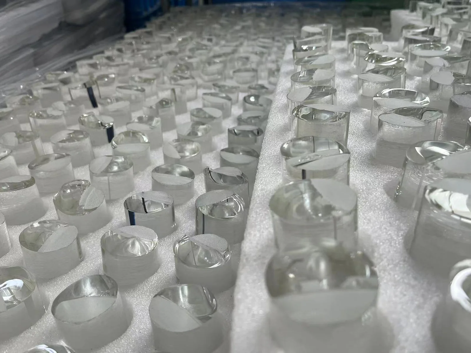
At a glance: Select the glass and preform as one process system. Optical constants, moulding behaviour, post-moulding index change, preform mass, geometry, surface condition and supply consistency should all be qualified before production release.
Use six questions to screen a candidate: Does it meet the spectral and optical requirements? Can its post-moulding optical constants be predicted or measured? Is there a practical forming window? Is it compatible with the mould and coating? Can a repeatable preform be supplied? Can the material remain available through the programme life?
Begin with the finished optical requirements
Start from the function of the finished component rather than from a preferred catalogue. Define the operating wavelength or spectral band, optical power, focal-length tolerance, clear aperture, operating temperature, environment, coating condition, component geometry, production quantity and service-life expectations.
Separate mandatory requirements from preferences. A candidate should not be rejected because one catalogue value differs slightly from the initial design if the system can be re-optimised without reducing performance. Equally, one glass should not replace another merely because their refractive index and Abbe number appear similar.
The data sheet review should connect each property with a design or process decision.
| Property group | Why it matters | What to confirm |
|---|---|---|
| Refractive index and dispersion | Optical power, chromatic correction and focal tolerance | Wavelength convention, catalogue tolerance, melt data and post-moulding condition |
| Internal transmission | Absorption, colour and usable spectral range | Wavelength, reference thickness and delivery-lot requirement |
| Transformation and viscosity data | Heating range, forming load and cycle development | Tg as a screening value, supported reheating range and viscosity behaviour |
| Thermal properties | Temperature equalisation, contraction and residual stress | Expansion interval, conductivity, density and heat capacity |
| Chemical properties | Cleaning, storage, coating and environmental durability | Supplier test method, resistance class and permitted cleaning chemistry |
| Internal quality | Scatter, wavefront and polarisation performance | Bubbles, inclusions, striae, homogeneity and stress birefringence |
| Supply information | Programme continuity and cost | Available forms, MOQ, melt frequency, lead time and change notification |
The drawing, material specification and supplier certificate should distinguish nominal catalogue information from properties guaranteed for the purchased delivery lot.
Evaluate index, dispersion and transmission
Refractive index must be tied to a wavelength. Optical-glass catalogues commonly report nd at the helium d-line near 587.56 nm or ne at the mercury e-line near 546.07 nm. A statement such as “refractive index 1.70” is incomplete without the wavelength and reference condition.
Abbe number is useful for initial screening, but two glasses with similar index and Abbe number can have different relative partial dispersion and residual chromatic behaviour. A demanding imaging design may also require Sellmeier coefficients, index tolerance, lot variation and data at every operating wavelength.
Transmission should be assessed across the actual spectral band. Internal transmittance excludes reflection losses; external transmittance includes the air–glass interfaces and therefore depends on index, surface condition and coating. Both depend on component thickness. Specify whether the acceptance value is internal or external, identify the reference thickness and state the coating condition.
For ultraviolet, near-infrared or laser applications, visible appearance and catalogue colour codes are not substitutes for wavelength-specific data. When the design operates near an absorption edge, verify the delivery lot or representative finished parts.
Temperature-dependent designs also need a consistent definition of dn/dT. State whether the value is absolute or relative, the measurement wavelength, reference temperature and surrounding medium. Model the change in index together with lens expansion, curvature and thickness changes, housing expansion, air-space shifts and the behaviour of adhesives or seals.[1]
Account for post-moulding optical-property changes
Precision moulding reheats the glass and cools it through the transformation region. This thermal history changes the structural state of the material and can shift refractive index and Abbe number relative to catalogue values based on a reference annealing condition. SCHOTT’s TIE-40 documents this index drop and provides reference information for precision-moulding glasses.[2]
The effect deserves particular attention in high-power lenses, multi-element imaging systems, high-index glasses, tight focal-length tolerances and assemblies with little focus adjustment.
Select one controlled design approach:
- Use supplier data for the expected moulding and cooling condition.
- Measure representative moulded samples after the process has stabilised.
- Apply a validated correction in the optical model.
- Use finished-component focal, wavefront or system performance as the controlling acceptance criterion.
Record which condition the optical prescription represents. Do not change the cooling cycle after optical validation without reviewing index, residual stress and dimensions.
Screen mouldability with Tg, viscosity and process risk
Glass transformation temperature, usually identified as Tg, is a useful screening property but not a moulding setpoint. The actual cycle depends on the viscosity required to fill the geometry, preform size, heating method, force or position strategy, mould material, release coating and contact time.
Low-transformation-temperature glasses can reduce thermal exposure and help extend mould or coating life. Some suppliers identify glass families developed specifically for precision moulding, but a low Tg or a “mouldable” label does not qualify every component and mould system.[2]
The process requires a repeatable window between two failure regions. If viscosity remains too high, the glass may not fill or replicate the cavity without excessive load. If it becomes too low, uncontrolled flow, edge overflow, unstable thickness or difficult release can result.
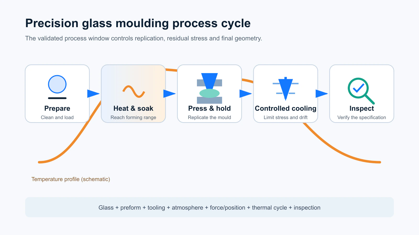
Long holds or repeated reheating can increase crystallisation risk. Devitrification may appear as haze, crystals, scatter or unstable surfaces, but similar symptoms can also come from contamination, coating transfer or glass–mould reaction. Diagnose them from controlled trials rather than appearance alone.
Glass constituents can interact with the mould, coating and process atmosphere. When introducing a new grade, qualify the complete glass–mould–coating–atmosphere system at representative temperature, contact time and load.
Review thermal, chemical and internal glass quality
Thermal expansion influences cavity-to-part contraction, compensation and stress during cooling. Use expansion values only over their stated interval; do not extend a room-temperature value through the transformation region without supporting data. Thermal conductivity, heat capacity, density and section thickness also influence heating uniformity and cycle time.
Residual temperature gradients can create incomplete replication, form error, residual stress, birefringence or cracking. Residual stress can affect dimensional stability and mechanical reliability; stress birefringence is its optical manifestation in transparent glass.
Chemical durability matters during cleaning, storage, coating and service. A sensitive glass may require controlled chemistry, rapid drying, protective coating, sealed packaging or environmental protection. Supplier resistance classes are not automatically comparable because test methods and exposure conditions can differ.[3]
Bulk material quality should be selected from the optical function and clear aperture rather than from a generic “highest grade” requirement.
- Bubbles and inclusions can scatter or block light; define permitted size, quantity, distribution and inspection region.
- Striae are local composition and index variations whose effect depends on orientation and optical path.
- Homogeneity controls spatial variation of refractive index and is important for wavefront-sensitive applications.
- Stress birefringence matters in polarisation-sensitive and precision imaging systems.
ISO 10110-18:2018 provides drawing conventions for stress birefringence, bubbles and inclusions, homogeneity and striae, and it applies to raw material as well as finished optical parts.[4]
Raw-material certification does not replace finished-part inspection. Cutting, preform preparation, reheating, pressing, cooling, handling and coating can introduce or change defects.
Compare preform types and geometry
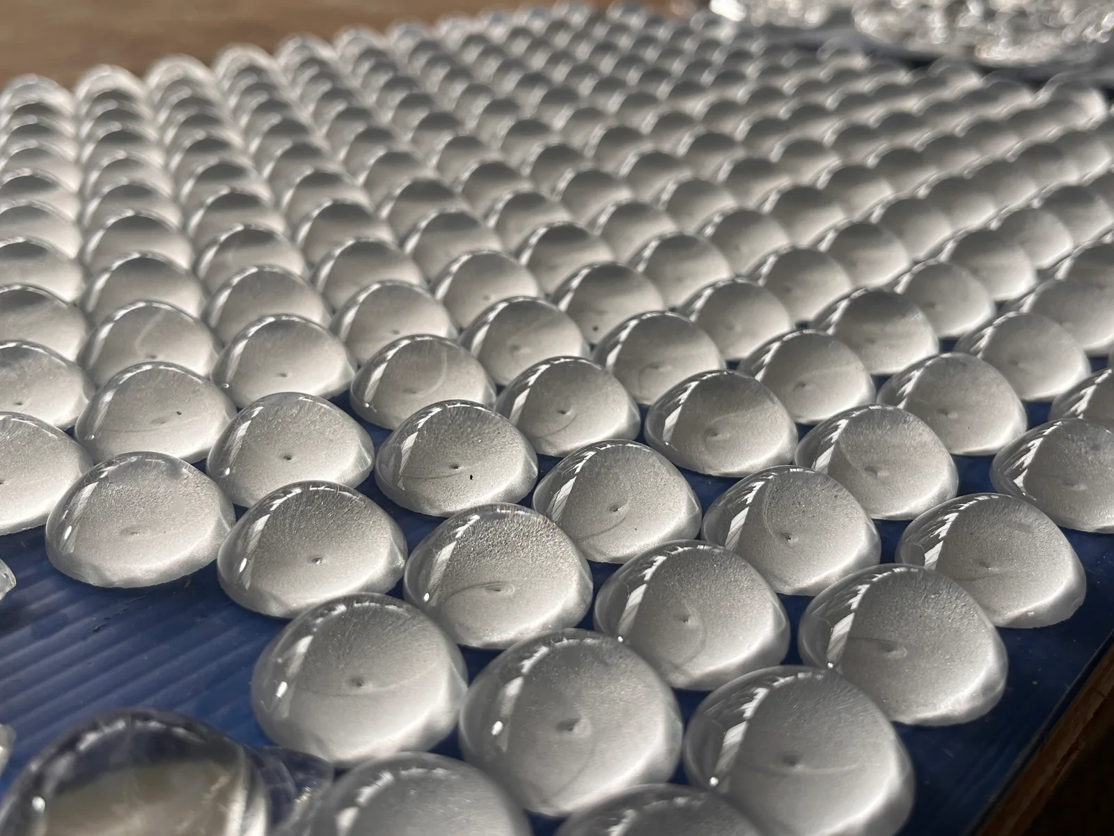
A preform is a prepared glass charge, not simply an oversized finished lens. Its shape determines the initial mould contact, stability during loading, heat-transfer path, radial flow distance, trapped-gas risk and edge formation.
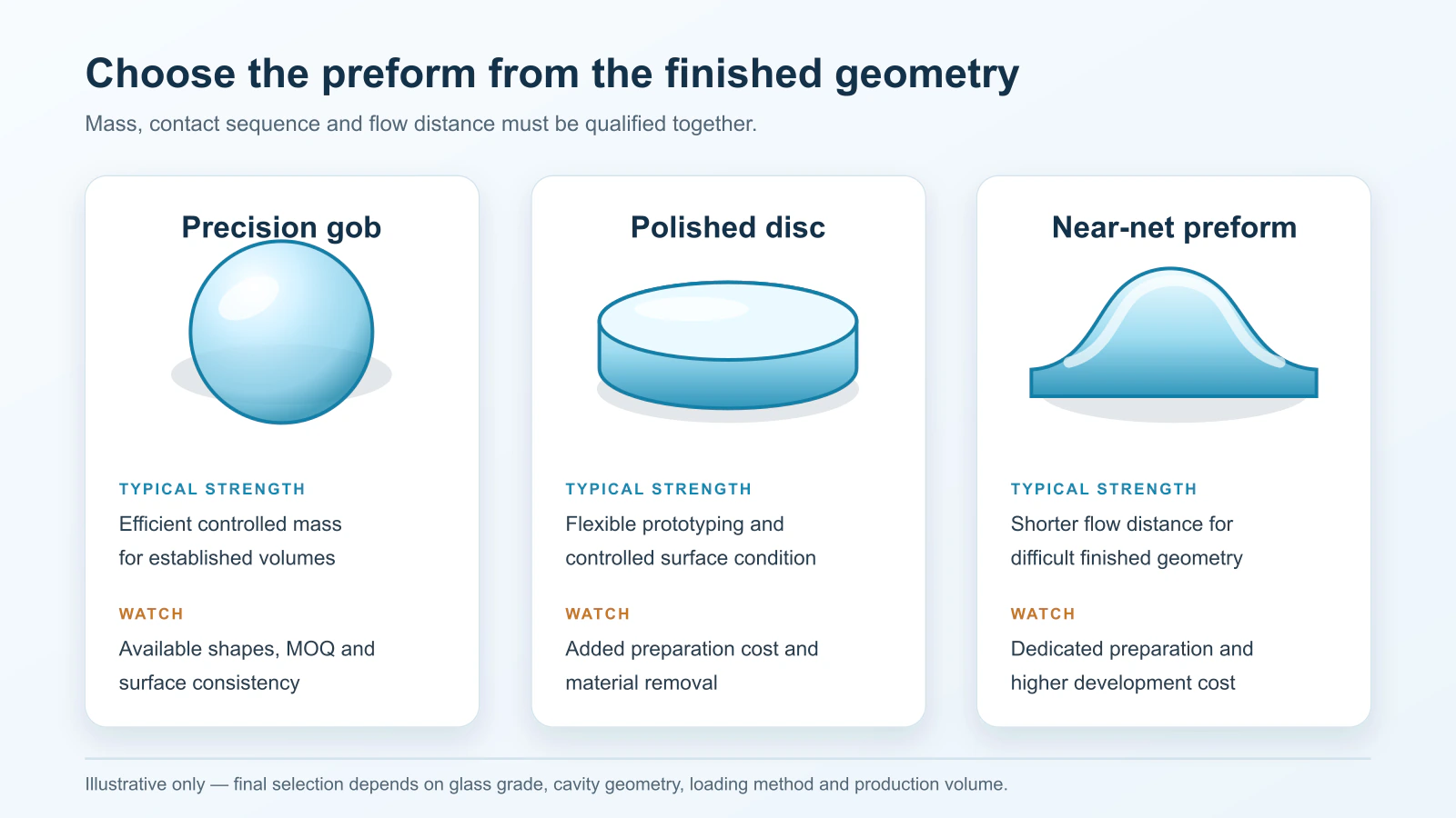
| Preform type | Best suited for | Main trade-off |
|---|---|---|
| Precision gob | Established volume production with a supported glass, shape and weight range | Supplier-specific MOQ, geometry and mass capability |
| Polished ball or disc | Development quantities, flexible geometry and controlled surface condition | Additional preparation cost, time and material loss |
| Near-net-shape preform | Difficult geometry where reduced flow distance or load is valuable | Dedicated preparation and higher development cost |
A ball can provide stable point or circular contact but may require large radial flow for a wide, thin lens. A disc positions more material near the final radius but introduces flatness, parallelism and orientation controls. A near-net preform can reduce displacement and forming load, although its own manufacturing route must be qualified.
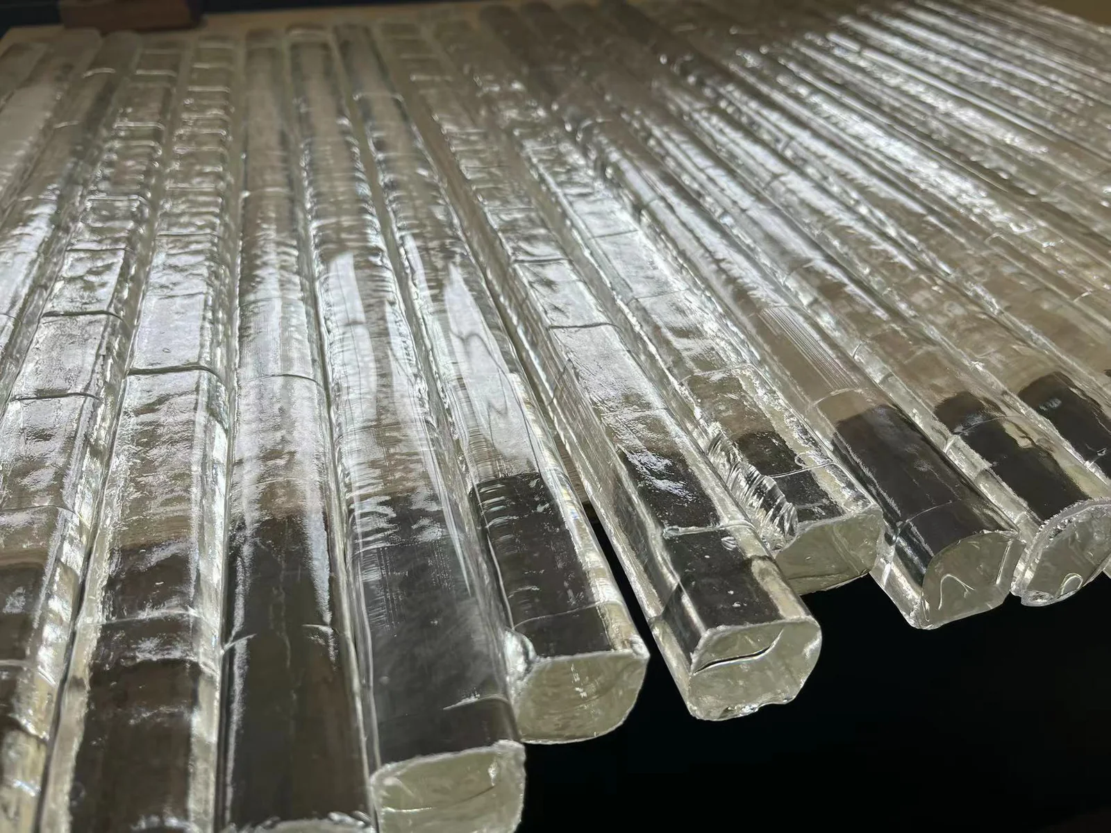
Choose from the finished cavity and loading method, not from the cheapest available blank in isolation.
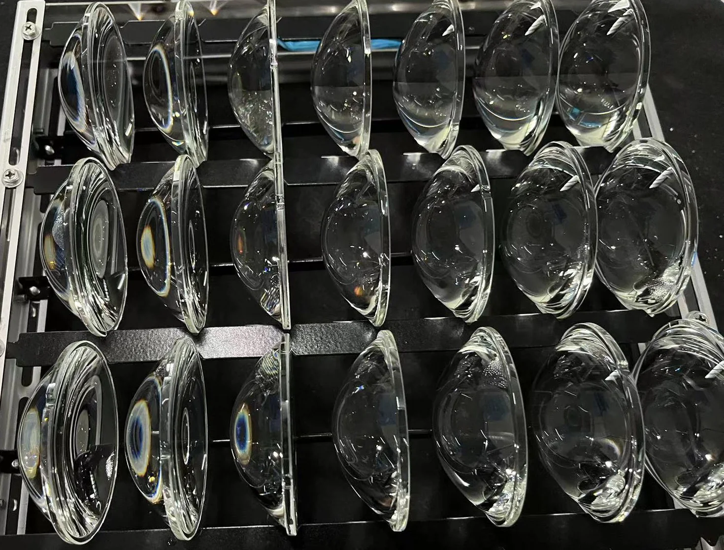
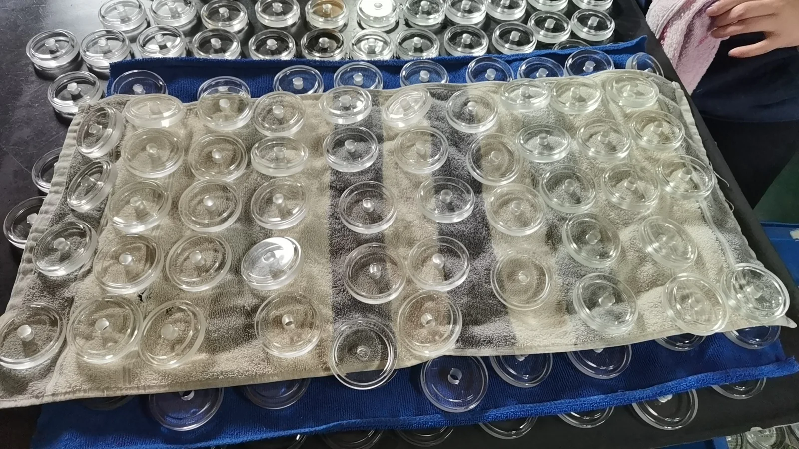
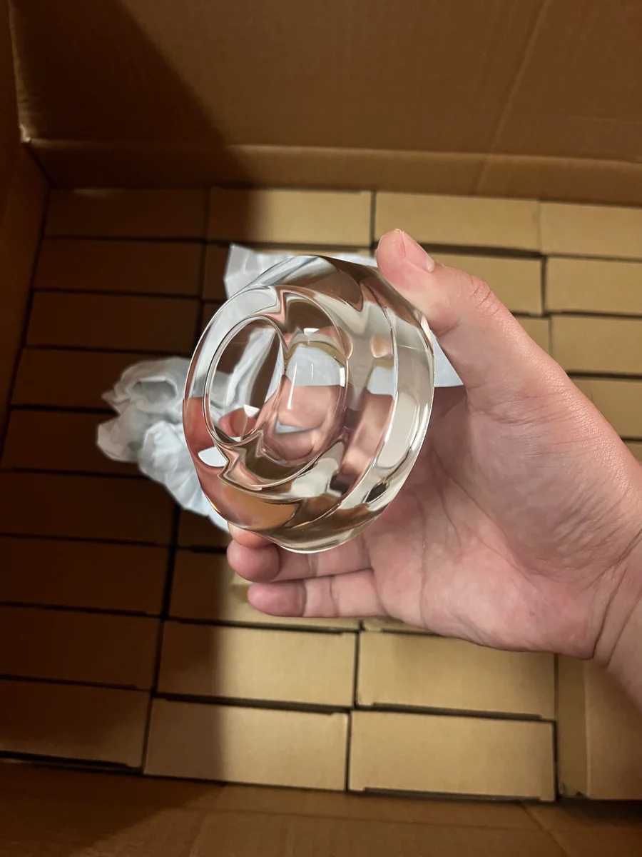
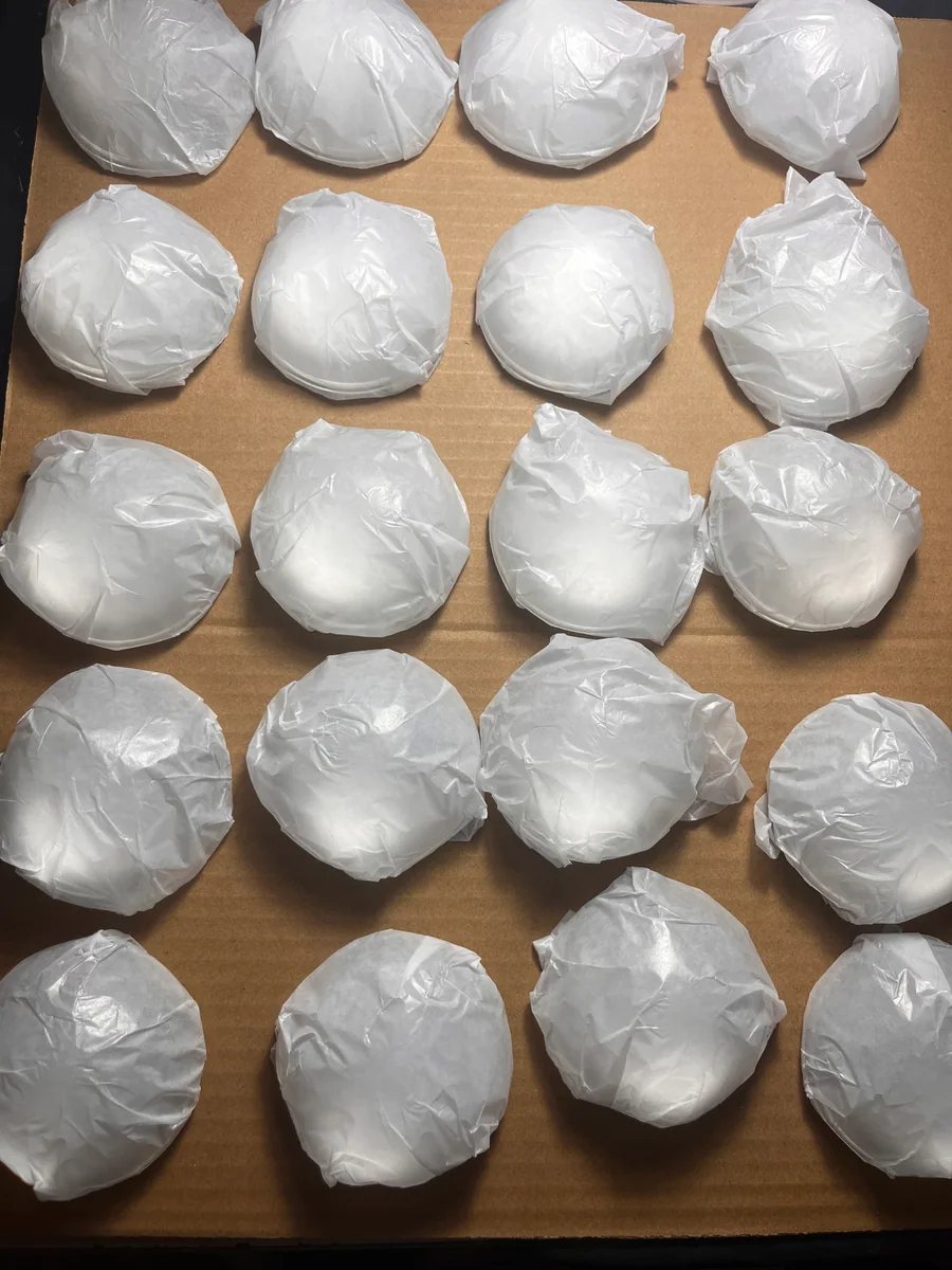
Examples of pressed glass lens geometries
The finished geometry determines how much glass must move, where the preform first contacts the mould and whether edge material or secondary finishing is required. These production examples show why one preform strategy does not suit every lens shape.
Control preform mass, dimensions and surface condition
Preform mass is one of the strongest controls on mould-closing position, centre thickness, edge thickness and overflow. Too little glass can cause incomplete filling or thin edges; too much can create overflow, thickness variation or tool contamination.
Calculate the starting target from finished-part volume and density, then account for thermal contraction, planned overflow, edge-finishing allowance and process-development evidence. Correlate trial mass with finished diameter, thickness, closing position, edge condition and replication before freezing the production window.
Mass alone is insufficient. Two preforms with identical mass but different diameter, height or curvature can heat and flow differently. Control only the dimensions that affect loading, centring, heat transfer, contact sequence or automated handling.
The surface specification should cover the supplied condition, permitted chips and defects, cleanliness, packaging and any required subsurface-damage control. Heating does not guarantee that deep grinding cracks will disappear. For a fire-finished gob, confirm that the supplier’s surface capability is suitable for the intended optical result.
Treat cleaned preforms as optical components. Approved cleaning chemistry must match the glass durability, and the procedure should define rinsing, drying, inspection, gloves, tools, clean storage and recleaning criteria. Dust, fingerprints, fibres, polishing compound and water spots can become trapped at the hot interface and imprint the glass or damage the coating.
Storage controls may include humidity, sealed packaging, desiccant, lot separation and a maximum time after cleaning. Inspect long-stored material for haze, staining, deposits and packaging marks before use.
Qualify supply, inspection and material changes
Incoming inspection should confirm that each delivery matches the approved glass and preform specification. The inspection plan can be risk-based, but its logic should be explicit.
| Characteristic | Typical evidence | Suggested control point |
|---|---|---|
| Glass identity and melt | Certificate and supplier traceability | Every delivery lot |
| Optical constants and transmission | Certificate, melt data or verification sample | Qualification and defined routine frequency |
| Preform mass and key dimensions | Incoming measurement | Every lot using an approved sampling plan |
| Surface and internal quality | Visual or instrument inspection under defined conditions | Every lot; increased during qualification |
| Cleaning and packaging | Process record and incoming condition | Every lot |
| Tg and other catalogue properties | Approved supplier data; test only when justified | Initial qualification and material change |
Trace finished production lots back to the glass manufacturer, grade, melt, preform supplier and lot, incoming record, cleaning batch, mould insert, coating condition, equipment, recipe and inspection report. Avoid unrecorded mixing of preform lots even when both meet the same nominal specification.
An alternative glass is a controlled material change, not an automatic drop-in replacement. Compare its full dispersion, transmission, thermal behaviour, density, durability, mould compatibility, available preform forms and supply status. A density change alters the mass required for the same cavity volume; index or dispersion changes require optical validation; thermal changes can affect the cycle and compensation.
The development source and mass-production source may be different. If a polished prototype preform will later become a dedicated gob, include that transition in the validation plan rather than treating it as a purchasing-only change.
Recommended selection and release workflow
Use a staged workflow that eliminates unsuitable combinations before committing to production tooling:
- Define optical, spectral, environmental and commercial requirements.
- Identify candidate glass families and distinguish mandatory values from preferences.
- Review dispersion, transmission, temperature behaviour and post-moulding optical data.
- Screen Tg, viscosity, crystallisation and glass–mould compatibility.
- Confirm available glass forms, MOQ, lead time and change-notification conditions.
- Calculate the initial charge and select a preform geometry from the finished cavity.
- Define mass, key dimensions, surface condition, cleaning and packaging.
- Obtain certificates and representative samples.
- Run compatibility and process-window trials using controlled mould and coating conditions.
- Measure finished optical, dimensional and internal quality.
- Refine preform and mould compensation, then validate repeatability across lots.
- Freeze the approved specification, incoming inspection and change-control plan.
The review package should contain the drawing, 3D model, optical prescription, preferred glass or permitted alternatives, wavelength and transmission requirements, operating environment, component volume, critical tolerances, coating condition, prototype quantity and annual demand.
Scope note: This guide provides general selection guidance. Final glass and preform suitability depends on the component geometry, mould system, process atmosphere, production equipment and agreed inspection method.
Frequently asked questions
Can any optical glass be precision moulded?
No. Optical performance must be considered together with viscosity, transformation temperature, crystallisation risk, glass–mould interaction and the availability of a suitable preform.
Is Tg the moulding temperature?
No. Tg is a screening property. The actual thermal cycle is developed from the viscosity required for filling and replication, together with the preform, geometry, mould and coating limits.
Why can refractive index change after moulding?
The moulding and cooling cycle changes the structural state of the glass relative to its reference annealing condition. The resulting index and Abbe number can differ from catalogue values.
When should a precision gob be used?
It is often attractive after the required material, mass and geometry are stable and the expected volume supports the supplier’s available weight range and minimum order quantity.
How is preform mass calculated?
Begin with cavity volume and glass density, then include planned overflow, secondary-finishing allowance and process-development data. Validate the target by correlating mass with finished dimensions and replication.
Key takeaway
Glass and preform selection is one linked engineering decision. A suitable material must meet the optical and environmental requirements after the production thermal cycle, while the preform must deliver repeatable charge, contact geometry, surface condition and supply consistency.
The release specification should identify the approved glass and preform, critical properties, inspection conditions, lot traceability and change-control rules. This creates a stable foundation for mould development, compensation and finished-part qualification.
Related technical guides
References
- SCHOTT optical-glass technical information downloads, including TIE-19 on the temperature coefficient of refractive index, TIE-29 on index and dispersion, TIE-31 on mechanical and thermal properties, and TIE-35 on transmittance. ↩
- SCHOTT TIE-40 — Optical glass for precision moulding, including precision-moulding glass families, preforms and the effect of moulding thermal history on optical properties. ↩
- SCHOTT TIE-30 — Chemical properties of optical glass, describing supplier-specific climatic, stain, acid, alkali and phosphate resistance classifications. ↩
- ISO 10110-18:2018 — Stress birefringence, bubbles and inclusions, homogeneity, and striae. ↩
Contact Us
Your feedback fuels our growth, and your questions drive our solutions.
We value your feedback, inquiries, and suggestions. Please feel free to get in touch with us
General inquiries
Please contact us via sales@bo-glass.com, and we will reply to you as soon as possible.
Interested to work with us
Drop your resume at info@bo-glass.com
and we will get back to you shortly.
We uses the contact information you provide to us to contact you about our relevent content, products, and services.