
Glass Screen Printing Process Control
Control the inputs that shape deposit, position and cure, then inspect before variation becomes a batch-level problem.
Engineering note: Typical starting values are provided for reference. Final tolerances and process parameters should be confirmed through sample trials using the specified glass, ink system, artwork and firing conditions.
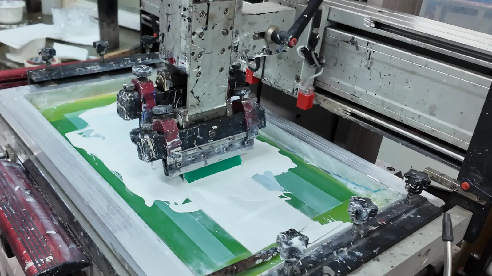
Define inputs, outputs and reaction rules
A robust process does more than list nominal settings. It identifies which variables are checked, how they are measured, who owns the decision and what happens when a limit is missed. Separate setup parameters from product results. Squeegee angle is an input; printed position, film mass, edge quality and optical density are outputs.
Use first-off approval after any change to screen, fixture, squeegee, ink batch or settings. Inspect early parts more frequently until the process is stable, then apply a sampling plan appropriate to the defect risk. Critical light masks or safety markings may need controls different from a decorative logo.
Traceability should connect a finished lot with glass batch or construction, cleaning route, ink and hardener batch, mix time, screen, press, operator, cure or firing record and inspection result. The level of detail should match product risk, but enough data must exist to investigate a complaint.
| Stage | Input check | Output check | Reaction |
|---|---|---|---|
| Glass preparation | Glass identity, surface condition, cleaner | Water break/contact-angle trend or agreed cleanliness check | Hold and reclean; investigate contamination source |
| Ink preparation | Batch, ratio, time, viscosity method | Print response and approved appearance | Stop addition; adjust only under written rule |
| Setup | Screen, fixture, squeegee, off-contact | Position, edge, deposit/opacity | Correct setup and repeat first-off approval |
| Production | Environment and timed ink checks | Sampled appearance and dimensions | Segregate since last accepted check |
| Cure/firing | Profile or dose | Adhesion, color and functional tests | Quarantine lot and assess rework feasibility |
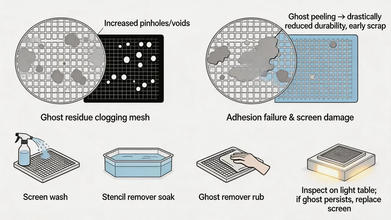
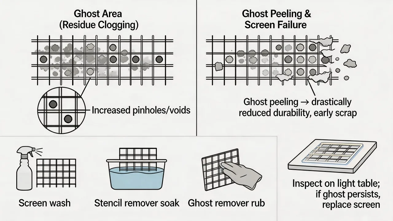
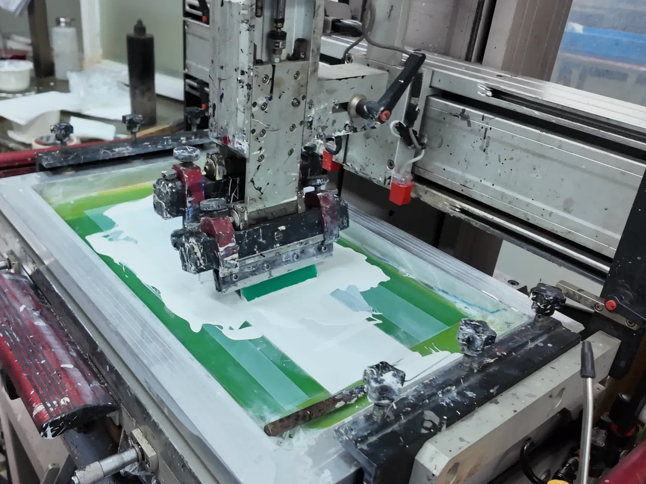
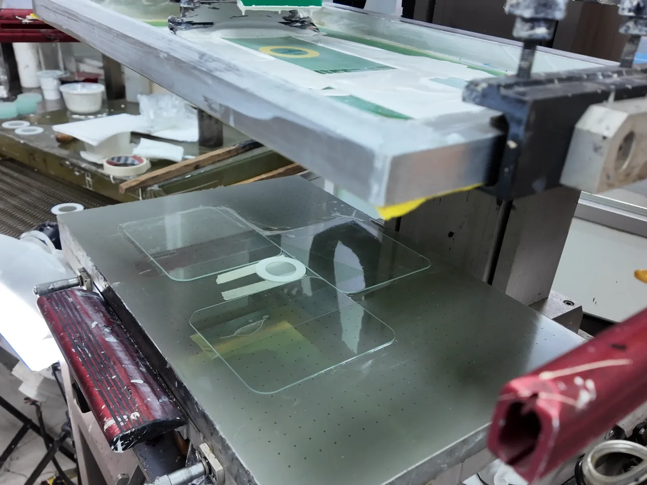
Squeegee selection changes both transfer and image shape
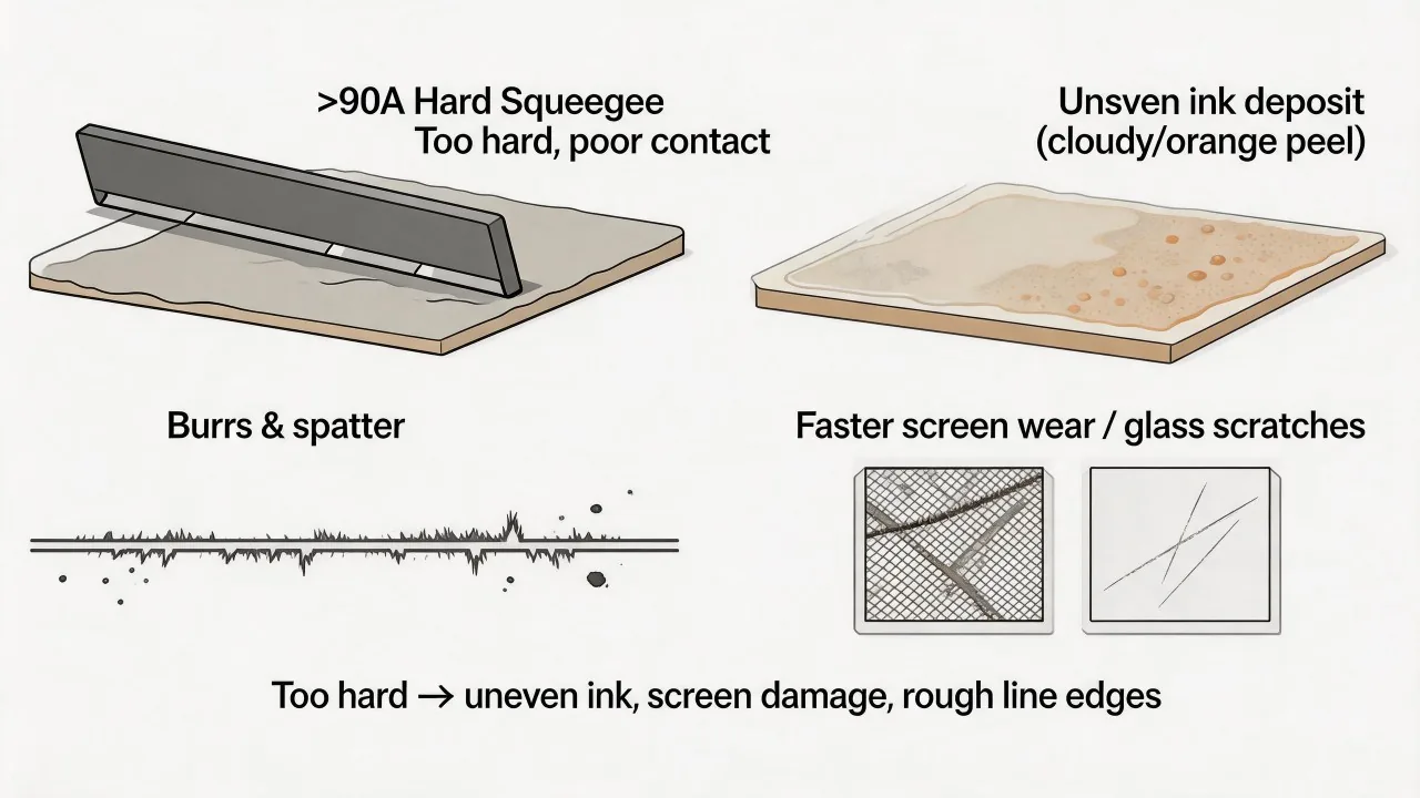
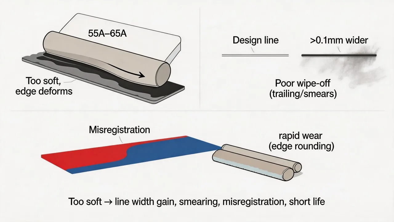
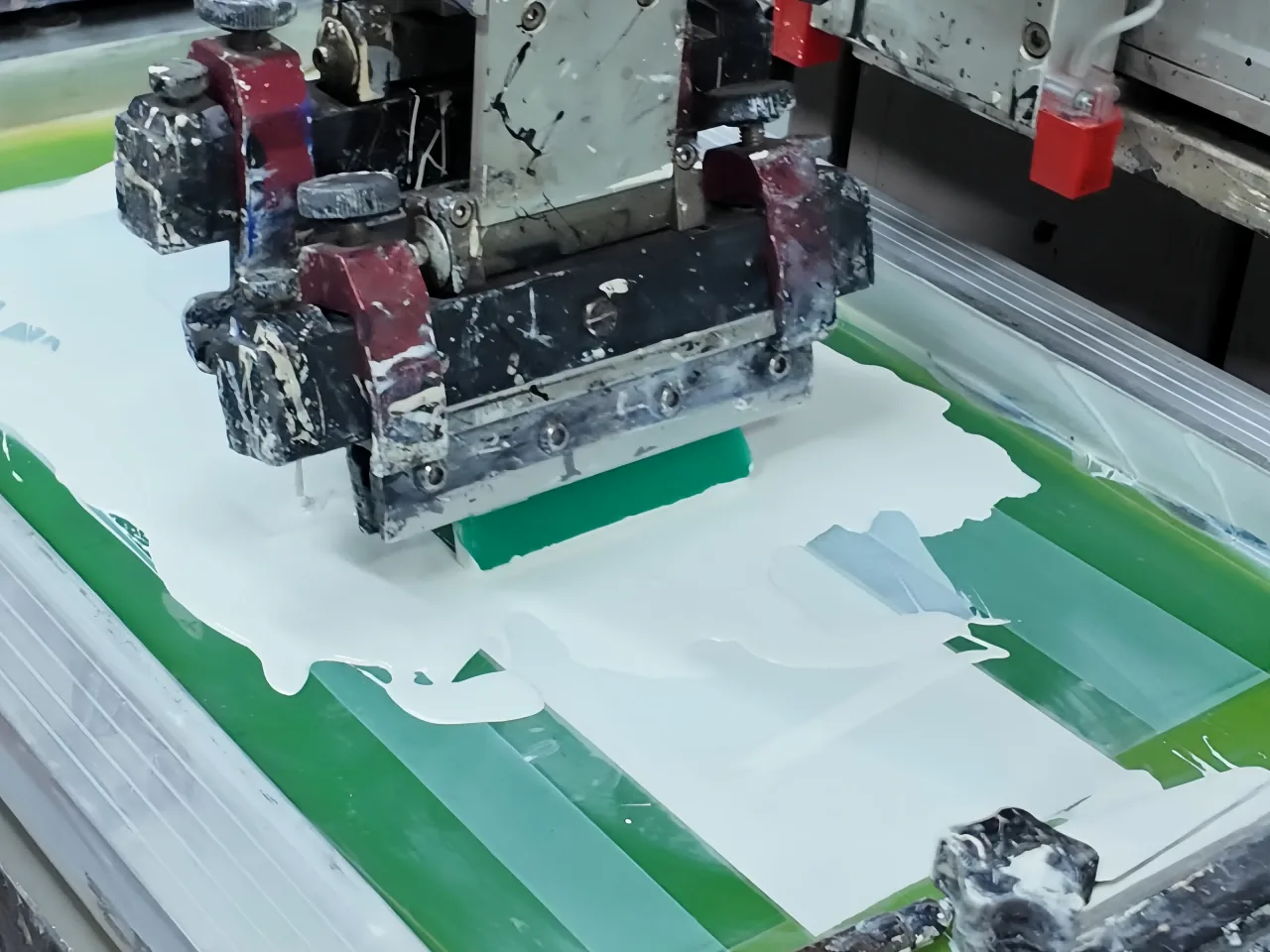
Hardness, profile, edge condition, angle, pressure and speed interact. A softer blade may conform and deposit more ink but can distort or smear fine work. A harder, sharp blade can support definition yet may deposit less or fail to follow uneven geometry. Use these tendencies to plan trials, then confirm the result on the specified setup.
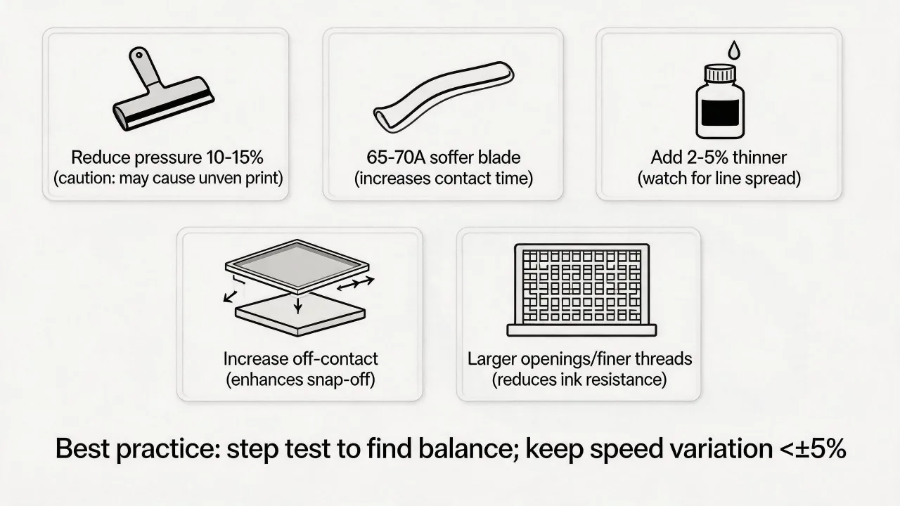
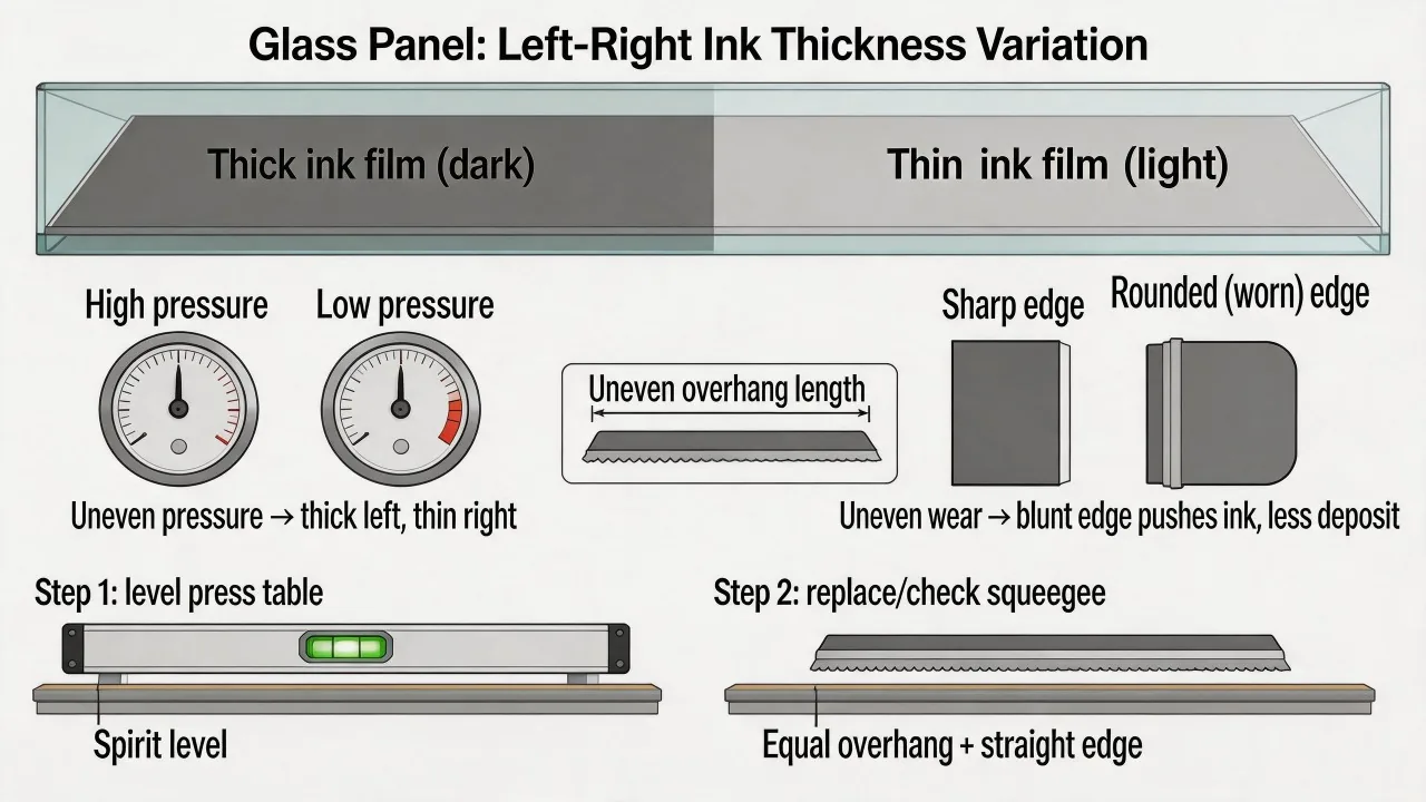
Use the minimum pressure that produces clean, complete transfer with reliable screen release. Excess pressure bends the blade, widens the contact zone and increases wear. Inconsistent pressure across the stroke can create a left-to-right deposit gradient that is incorrectly blamed on ink.
Record blade type and usable edge. Rotate or replace a worn blade under a defined rule. A visual check alone may miss rounding or local damage. When troubleshooting, substitute a known-good blade before changing several process settings at once.
Control time-dependent rheology and speed together
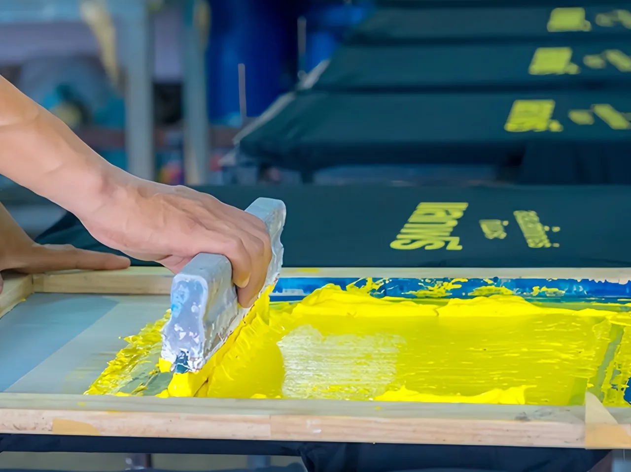
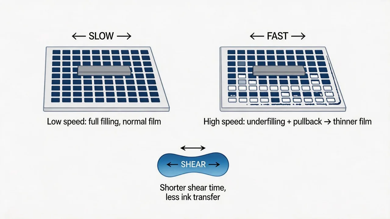
Higher print speed may reduce transfer time and change the deposited film. Ink rheology, screen release, flood quality and blade deformation determine the direction and magnitude of that change. Base compensation on the measured deposit or optical result before adjusting pressure or thinner addition.
Mix and condition ink using the supplier’s instructions. For multi-component systems, control ratio, induction time and pot life. Define a viscosity method with spindle or cup, temperature and measurement timing so measurements remain comparable.
Solvent addition can change drying, edge definition, deposit and final properties. Use only approved additions and record them. Cover or manage the ink during interruptions. Restart after a stop with an inspection because material held in the screen may behave differently from freshly flooded ink.
Map gradients before choosing a cause
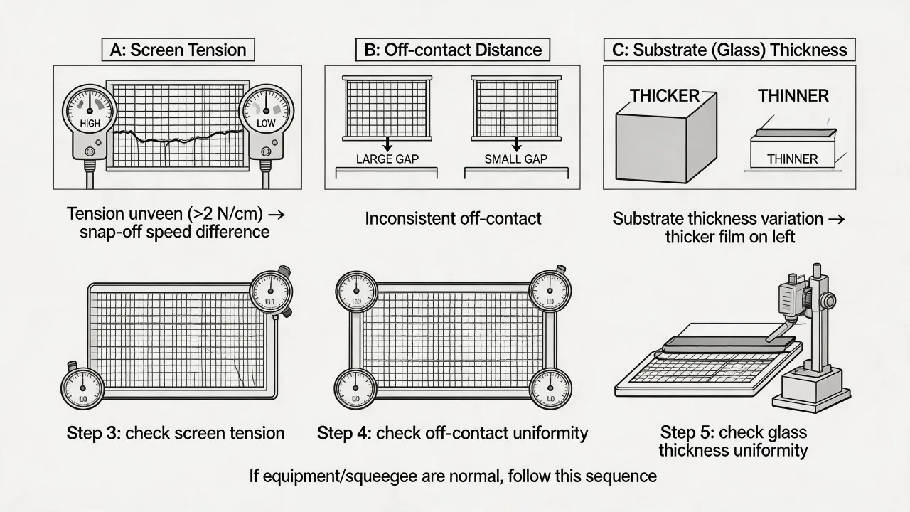
One side of a panel printing heavier than the other can come from screen-to-table parallelism, non-uniform off-contact, fixture height, glass thickness or warp, squeegee pressure, blade straightness, flood behavior, tension variation or press motion. Evaluate a stated glass-thickness tolerance such as ±0.2 mm together with fixture support and process compliance.
Print a diagnostic solid or grid and map thickness, mass, optical density or color across the panel. Check fixture and screen geometry with independent measurements. Rotate the screen, squeegee or part where safe to see whether the gradient follows a component. Change one factor at a time.
Support the glass without creating stress or rocking. Vacuum location and gasket condition may imprint the print result. For shaped or tempered glass, measure actual form and assess whether a family of fixtures or compliant support is needed.
For voids, craters or directional marks, continue with the defect-morphology review →
Set cleanliness from product-specific defect risk
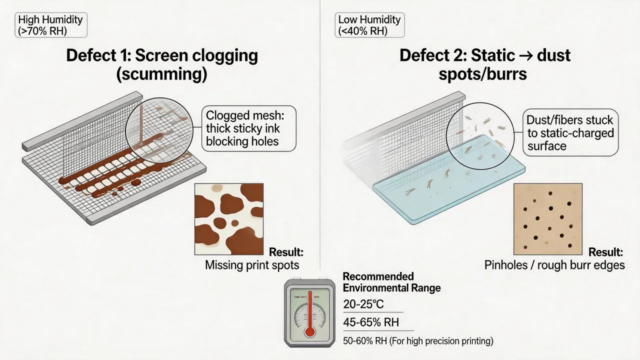
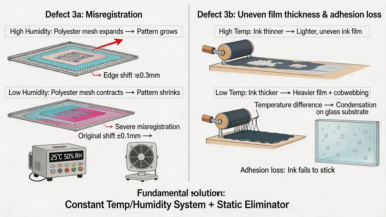
Temperature and humidity can affect ink viscosity, solvent loss, static, stencil behavior and condensation. Dust, fibers and dried ink can create pinholes or inclusions. Set an operating window from the chosen materials and equipment, then monitor it where printing occurs.
Choose the appropriate cleanroom classification or local clean-air control from the allowed particle size, visible-defect criterion, part exposure time, cleaning method and customer requirement. Targeted clean-air measures may provide effective control for the defined process zone.
Separate glass cleaning from sources of silicone, oil, release agents and aerosol maintenance products. Use clean, compatible gloves and supplement contact-angle or water-break checks with controls for localized silicone, fibers, particles and contamination introduced after measurement.
Multiple passes and glass side require trials
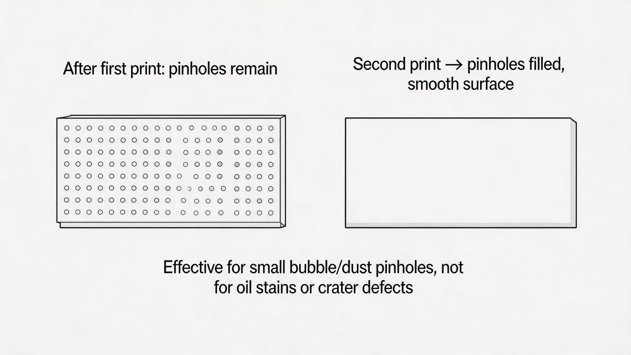
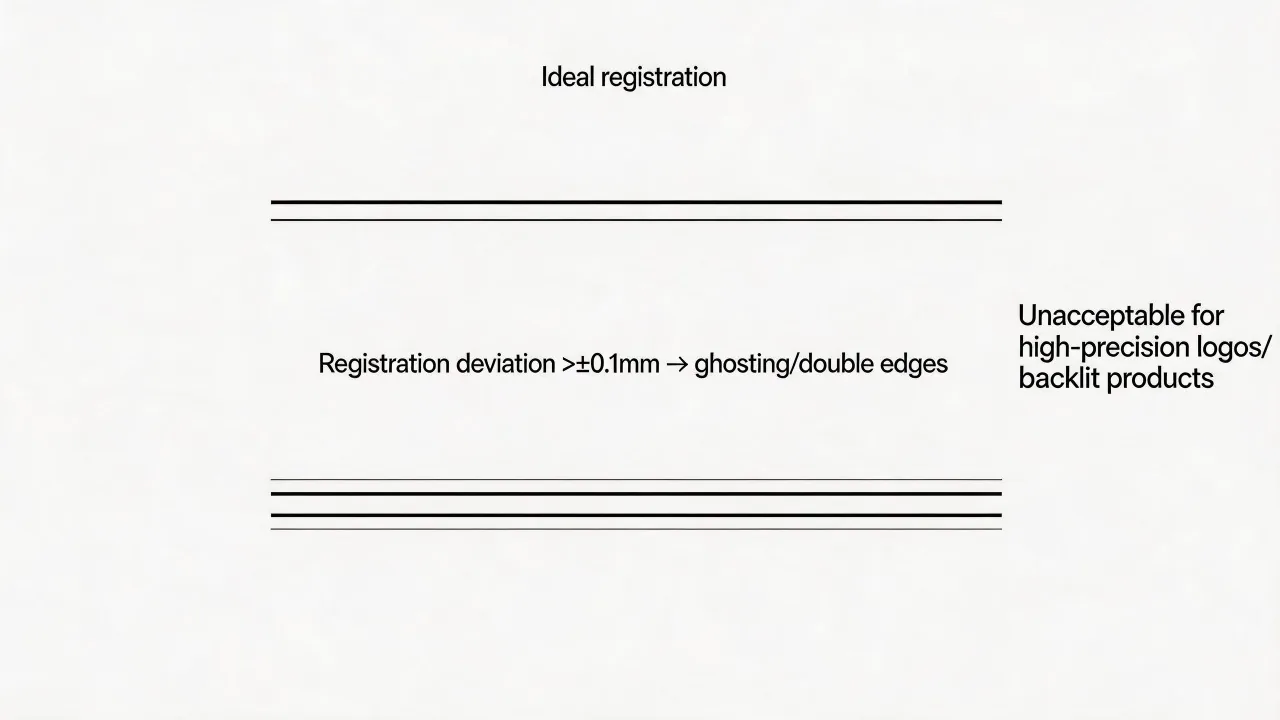
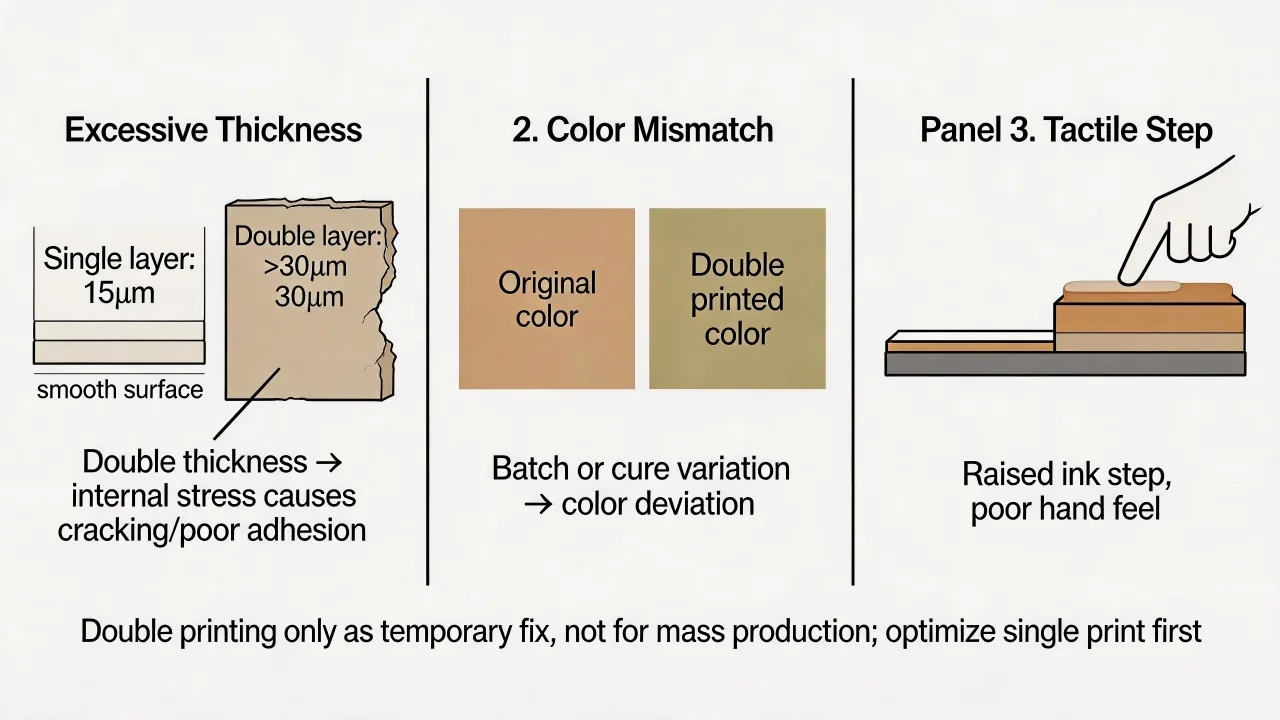
A second print pass may cover some pinholes, but it can also trap solvent, increase thickness, shift registration, change color, bridge detail or create bubbles during firing. Investigate the pinhole source first. If double printing is selected, define intermediate flash or drying, alignment and total film limits, then validate the complete cure.
Printing on the air side of float glass is sometimes preferred. Select the print side from the glass, ink, surface treatment and firing system. Identify both sides with an agreed method and run adhesion, appearance and thermal trials on the intended orientation.
Tempered glass requires a route decision. Ceramic enamel is commonly printed before tempering and fused during the cycle. Post-temper decoration usually uses a low-temperature organic ink selected for the required performance. Formed tempered glass requires dedicated tooling and a printability trial to establish deposit quality and positional precision.
← Screen Making, Mesh and Exposure Control | Main guide | ceramic enamel Firing and Glass Tempering →
Contact Us
Your feedback fuels our growth, and your questions drive our solutions.
We value your feedback, inquiries, and suggestions. Please feel free to get in touch with us
General inquiries
Please contact us via sales@bo-glass.com, and we will reply to you as soon as possible.
Interested to work with us
Drop your resume at info@bo-glass.com
and we will get back to you shortly.
We uses the contact information you provide to us to contact you about our relevent content, products, and services.