
Screen Printing Guide
What is screen printing?
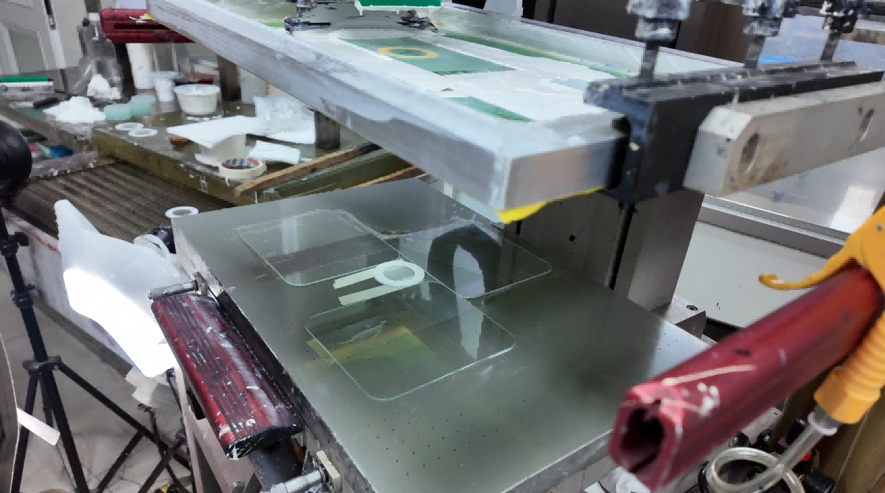
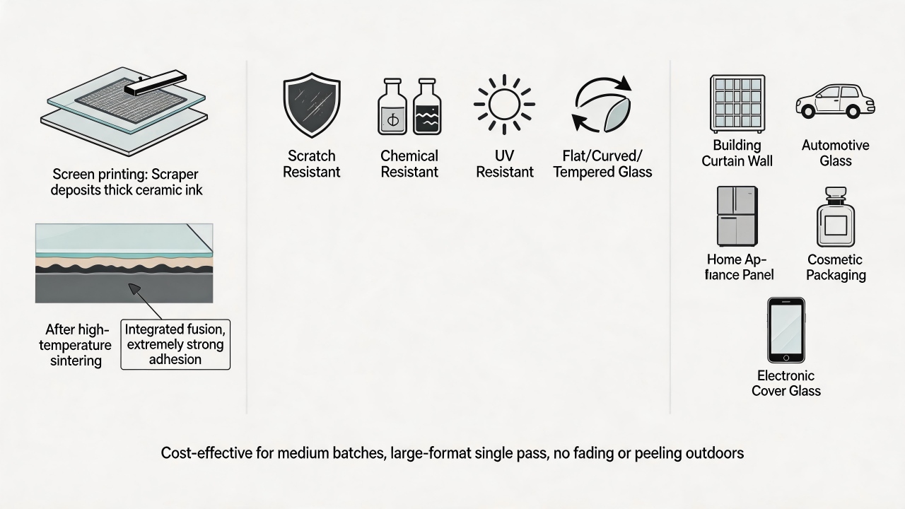
Screen printing is an ancient yet highly versatile printing technique whose core principle can be summarized as "stencil printing" or "through-printing." In simple terms, the screen printing process is akin to printing with a hollowed-out stencil, but its sophistication lies in the fact that this "stencil" is a fine mesh stretched tightly over a frame. First comes plate-making: on the screen mesh, the areas corresponding to the desired pattern remain open and unblocked—these are known as the image areas; the areas that are not meant to be printed are sealed off with a layer of photosensitive emulsion, forming the non-image areas, and this creates a completed screen plate. During printing, the screen plate is positioned with a slight gap above the surface of the object to be printed, and ink is then poured onto one end of the screen. Using a rubber squeegee applied with consistent pressure and at a specific angle, the ink is drawn across the screen from one end to the other. Under the pressure of the squeegee, the screen momentarily makes linear contact with the surface below, forcing the ink to pass through the open mesh of the image areas and transfer onto the object. As soon as the squeegee passes, the screen, relying on its inherent tension, snaps back and separates from the object, leaving the ink precisely deposited on the surface, and in this way, the pattern is completely printed.
Core Advantages and Applications
Core Advantages and Applications In the field of glass screen printing, this technology possesses several irreplaceable advantages. First, it is capable of depositing an extremely thick ink layer on the glass surface, and when ceramic inks are used followed by high-temperature sintering, the ink fuses integrally with the glass, resulting in exceptionally strong adhesion that is resistant to scratching, acids, alkalis, and ultraviolet radiation, ensuring the pattern will not fade or peel even after prolonged outdoor exposure. Second, screen printing adapts to various glass configurations—whether flat glass, curved glass (such as 2.5D contoured edges), or tempered glass—as long as the squeegee can make contact, precise printing can be achieved. Third, by selecting screens of different mesh counts and varying emulsion thicknesses, glass screen printing can produce both large solid background colors and reproduce fine lines and text, making it widely applied in architectural curtain walls, automotive glass, household appliance panels, cosmetic bottles, and glass cover panels for electronic products. Finally, for medium-batch production of glass items, the plate-making cost of screen printing is relatively manageable, and it enables large-format printing in a single pass, offering a high overall cost-performance ratio, which has established it as one of the mainstream processes for decorative and functional coatings in the glass deep-processing industry.
What are some common screen printing problems?
In terms of design fundamentals, what are the most common mistakes designers make?
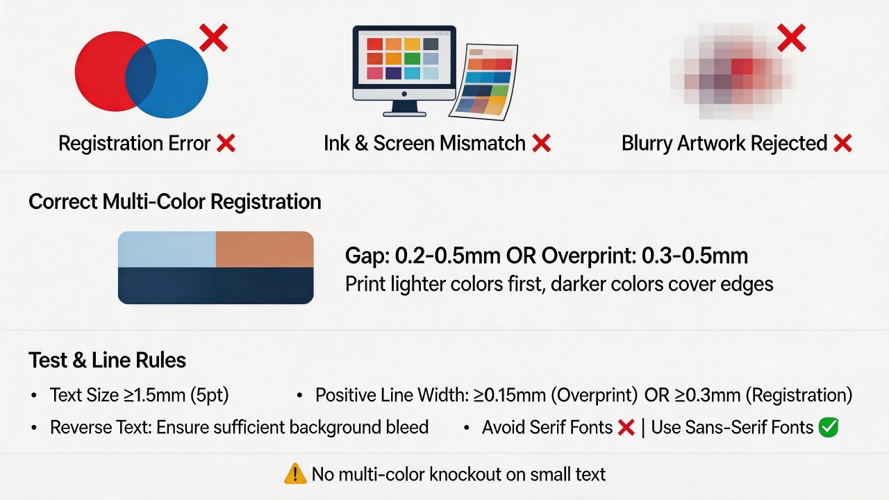
Screen printing is inherently a "subtractive" process, and designers should avoid pursuing multi-color registration, as this not only drives up costs but also makes misregistration highly likely; at the same time, one must not rely excessively on on-screen effects but rather understand the actual disparities between ink and substrate, and for issues such as blurry originals or coarse grain, the source material should be firmly rejected rather than wasting time on inherently flawed assets.
When multi-color registration printing is performed, how can one prevent colors from "fighting" each other?
When adjacent colors meet, either leave a gap of 0.2-0.5mm or design an overprint of 0.3-0.5mm; otherwise, registration deviation will lead to white gaps or unintended overlapping; for fine lines below 0.3mm, it is strongly recommended to use overprinting rather than trapping, and to make the lighter color area slightly larger and printed first, allowing the darker color to cover the edge, thereby tolerating minor deviations.
What are the "passing marks" for text and line design?
Text should not be smaller than 1.5mm (approximately 5 points), overprinted line width should be ≥0.15mm, and registration line width should be ≥0.3mm; for reversed-out text, be vigilant against insufficient background expansion that can cause characters to fill in or merge, and it is advisable to select sans-serif typefaces, avoiding fonts like Songti with significant stroke contrast, and furthermore, one should never attempt multi-color knockout or overlaid registration on small text.
What are the "forbidden zones" concerning color and halftone dots?
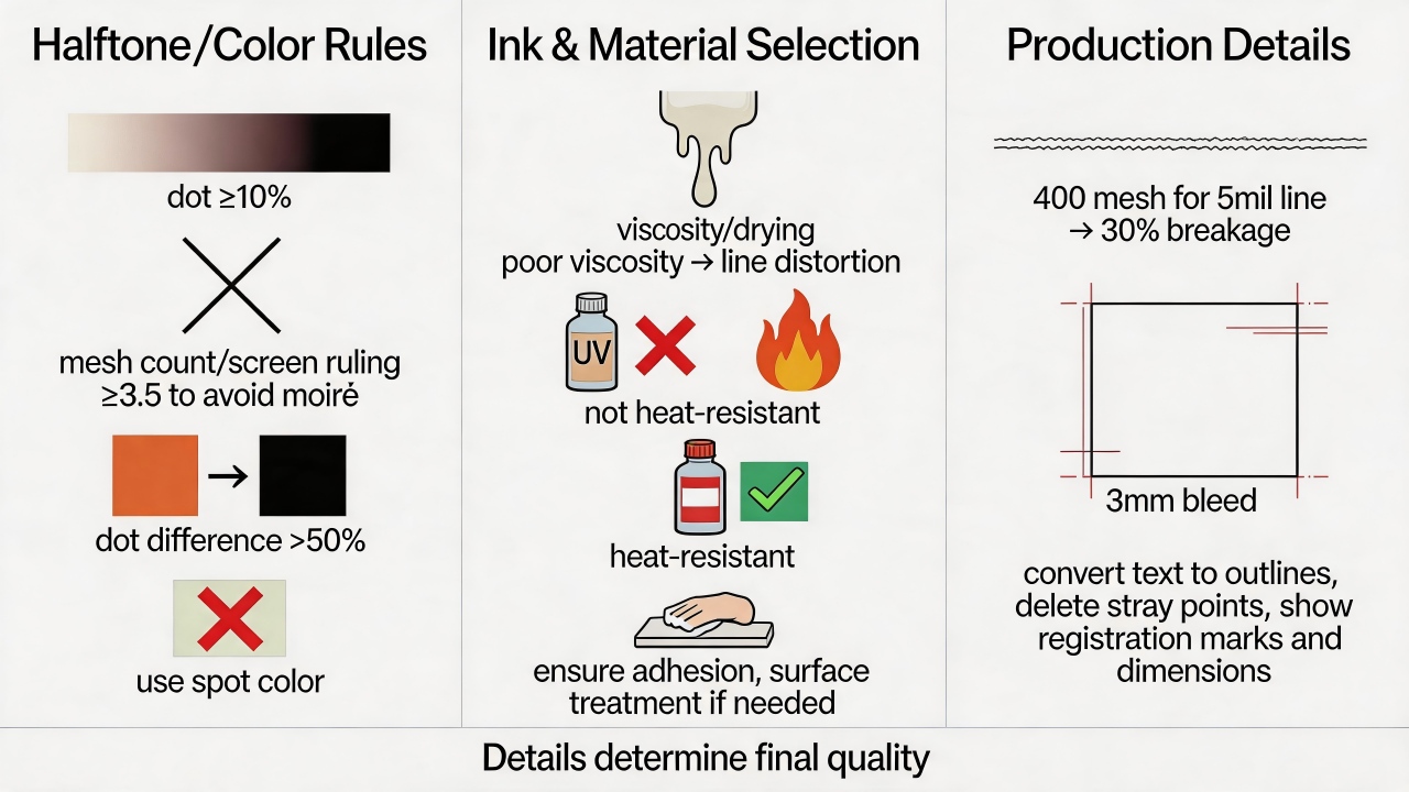
When creating gradients, the minimum dot percentage should ideally not be less than 10%, otherwise dots are prone to dropping out; when printing halftone dots, attention must be paid to the ratio between screen ruling and mesh count (recommended at 1:3.5 or higher), and screen angles must be correctly set to prevent moiré patterns; if text and background share the same color family, the dot percentage difference should be increased to over 50%; for light tints below 20%, it is advisable to substitute with a spot color to avoid uneven ink coverage.
What is easily overlooked in ink and material selection?
Ink viscosity and drying speed directly affect line definition, and ink that is too thin or too dry will both lead to distortion; although UV ink cures quickly, it lacks high-temperature resistance, and for high-temperature environments, solvent-based or dual-cure inks should be selected instead; prior to printing, the substrate surface must be ensured clean, and surface treatment should be performed when necessary, otherwise poor ink adhesion will result in subsequent peeling or detachment.
What are the fatal pitfalls in production details?
Excessively low screen mesh count will allow an excessive amount of ink to pass through, resulting in edge burrs—for instance, when printing a 5-mil line width with a 400-mesh screen, the character breakage rate can reach 30%; a 3mm bleed must be reserved on each side of the layout; before delivering files, text must be converted to outlines (curves) and stray points must be deleted, while dimensions, registration marks, and cursor positions must be clearly indicated—these details may seem trivial, yet they are crucial in determining whether the finished product meets the required standards.
Which defects can be reworked (e.g., washed and reprinted) and which defects can only be scrapped?
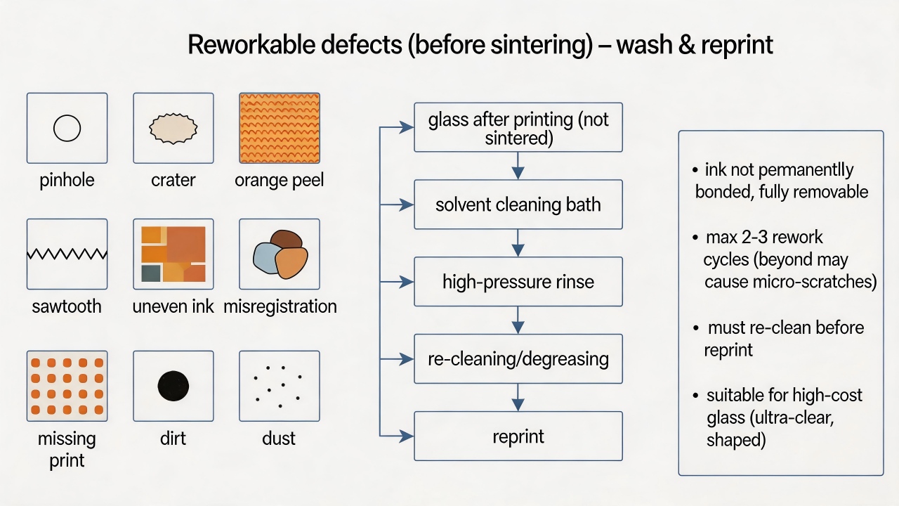
In glass screen printing, the core criterion for determining whether a defect is "reworkable" or "must be scrapped" is whether the defect has damaged the original surface of the glass substrate and whether the ink has already undergone irreversible sintering or tempering. Simply put, most defects occurring after printing but before sintering can be reworked; defects occurring after sintering (especially after tempering) can, in the vast majority of cases, only be scrapped.
Defects that can be reworked (washed and reprinted) share the common characteristic that the ink has not yet undergone high-temperature sintering or formed a permanent chemical bond with the glass, and the ink layer can be completely removed by chemical or physical means without damaging the glass surface. Specifically, these include defects occurring during the printing process such as pinholes, craters, orange peel, slight sawtoothing, uneven ink laydown, pattern misalignment, missed prints, dirt spots, and embedded dust particles—as long as the glass has not yet entered the sintering furnace when such defects are discovered, they can be thoroughly cleaned off using a dedicated screen wash or solvent, after which the glass can be reprinted. After washing, the glass surface must be recleaned and degreased to ensure no residual solvent or ink traces remain; otherwise, adhesion may be compromised or new craters may appear during the second print. Unsintered test prints and defects present after drying but before sintering can also be recovered through washing and reprinting, a practice that is particularly economical for higher-cost glasses such as ultra-clear glass or irregularly cut glass. However, multiple washings (exceeding two or three times) may lead to micro-scratches or chemical etching on the glass surface, affecting subsequent adhesion; reworked glass must strictly undergo the complete cleaning process again and should be reprinted as soon as possible rather than stored for extended periods.
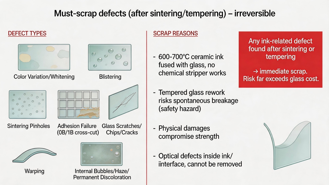
Defects that can only be scrapped share the common characteristic that the ink has already formed an irreversible bond with the glass, or the defect has altered the physical or chemical properties of the glass such that recovery is not economically feasible. Specifically, these include products that have already undergone high-temperature sintering or tempering: at 600 to 700°C, ceramic ink fuses integrally with the glass, and no chemical cleaner can strip it away; attempting to use strong acids, strong alkalis, or mechanical abrasion will severely damage the glass's surface flatness and optical performance, and for tempered glass may also pose a risk of spontaneous breakage. Therefore, all defects discovered after sintering or tempering (color variation, whitening, blistering, pinholes, insufficient adhesion, etc.) should be scrapped directly. Physical damage to the glass substrate itself—such as scratches, chipped edges, broken corners, or cracks present before printing, or glass breakage and edge impacts incurred during printing—compromises the glass's strength and safety performance and mandates scrapping. Severely warped or distorted glass, where warping results from excessive sintering temperature, improper loading, or inherent glass quality issues and cannot be corrected through subsequent processing, must be scrapped when precise assembly is required. Complete adhesion failure, where post-sintering cross-cut testing yields a severely failing grade (e.g., 0B or 1B) and the ink peels off in flakes, indicates that no effective bond formed at the interface; sanding and reprinting would destroy the stress layer of tempered glass and is cost-prohibitive, so such glass is typically scrapped outright. Irreversible optical defects—such as internal bubbles appearing after sintering, a hazy layer formed by ink-glass reaction, or permanent darkening or yellowing of ink color due to over-firing—reside within the ink layer or at the interface and cannot be eliminated through surface treatment.
In very rare instances, certain post-sintering defects may be subjected to limited rework via "overcoating," though this requires careful evaluation. For example, localized pinholes or craters on a light-colored ink may be manually touched up using the same color ink followed by low-temperature curing (without re-tempering), but the durability (scratch and alcohol resistance) of the repaired area will be noticeably inferior to normally sintered areas; this approach is only suitable for decorative glass with lower durability requirements and must receive written acceptance from the customer. Overall color deviation (ΔE between 2 and 3) may, if the customer permits, be corrected by printing an additional semi-transparent ink layer over the original pattern, though this requires re-sintering and is applicable only to non-tempered glass; it carries risks of glass deformation or reduced adhesion from a second firing and is generally not recommended.
On the production floor, a rapid judgment workflow can be established: all printing defects prior to sintering are reworkable, but the number of rework cycles should be recorded (two cycles recommended maximum), and cleaning quality inspection for reworked glass should be intensified; for minor appearance defects after sintering (non-tempered), touch-up may be attempted or client acceptance sought, while severe defects are scrapped directly; any ink-related defect after tempering is scrapped immediately with no rework attempt, because the risk of spontaneous breakage during any subsequent processing of tempered glass increases significantly, potentially causing personal injury or customer claims—a risk far outweighing the cost of a single sheet of glass.
Finally, it is recommended to implement a "pre-sintering full inspection" system to intercept defects before they enter the furnace, rather than relying on post-sintering rework—rework is merely a cost-control measure, whereas zero defects remains the ultimate goal.
Common Customer Questions Regarding Screen Printing
Can large solid background areas and fine lines be accommodated on the same screen?
From a technical standpoint, achieving perfection is difficult, and one typically must compromise on one aspect or employ specialized techniques. This is because the requirements these two elements place on the screen are inherently contradictory: large solid background areas demand large mesh openings and ample ink deposit—in order to print evenly, densely, and without pinholes, low mesh counts (e.g., 100-200 mesh) and thick emulsion stencils are generally used; fine lines, on the other hand, require narrow openings and sharp edges, necessitating high mesh counts (e.g., 300-420 mesh) and thin emulsion stencils. The threads of low-mesh-count fabric are relatively thick and cannot support extremely fine lines; forced printing will result in jagged edges or even broken lines. High-mesh-count fabric has small openings and poor ink passage, leading to faint, uneven solid areas with orange peel texture or pinhole-like voids when attempting large solid coverage. Moreover, it is exceedingly difficult to simultaneously create both thick and thin emulsion regions on a single screen, and thick emulsion sections are prone to peeling off during printing.
Under what circumstances, then, can one tentatively attempt to combine them on the same screen? If you must place both on a single screen, very stringent conditions must be met: in terms of design, the fine lines cannot be too thin (a minimum of 0.2-0.25 mm is recommended), and it is preferable to have halftone dots or texture transitions around the lines; use high-tension, dyed yellow mesh (e.g., 300-350 mesh) and an extremely thin emulsion coating (5-8 microns); employ a hybrid "thick film/thin film" stencil-making process, such as applying capillary film twice—using thin film for fine line areas and layering additional thick film over solid background areas. The ink must also be thinned considerably to facilitate greater ink passage through the high-mesh-count screen. Even so, you must accept imperfect results: the lines may exhibit slight jaggedness, or the solid background may retain a faint mesh texture. This approach is costly, yields low production rates, and is generally reserved for low-end products or sample making.
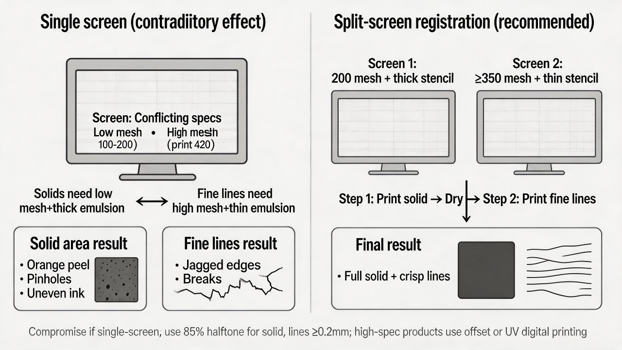
In actual production, when faced with a "large solid background plus fine lines" design, the more professional and reliable approach is to separate the screens for registration printing. This involves making two distinct screens: one of around 200 mesh with a thick stencil for the solid background, and another of 350 mesh or higher with a thin stencil for the fine lines. Print the solid background first, allow it to dry, and then print the fine lines. This yields the best results and the highest yield rate.
If constrained by registration accuracy or equipment limitations, an alternative is to render the solid background area as a high-percentage halftone dot (e.g., 85% round dots) rather than 100% solid, enabling better printing through a high-mesh-count screen while keeping the fine lines as 100% solid, thereby approximating a solid appearance from a distance.
For high-specification products such as panels or electronic nameplates, it is advisable to forgo screen printing altogether and opt for offset printing or digital UV flatbed printing—offset printing can readily achieve highly saturated solids and lines below 0.1 mm, while digital printing imposes no screen-related constraints whatsoever.
In summary, if separation is possible, avoid combining them; if a single screen must be used, expect either thicker lines or a mottled solid background.
Is a minimum line width of 0.3mm an absolute limit?
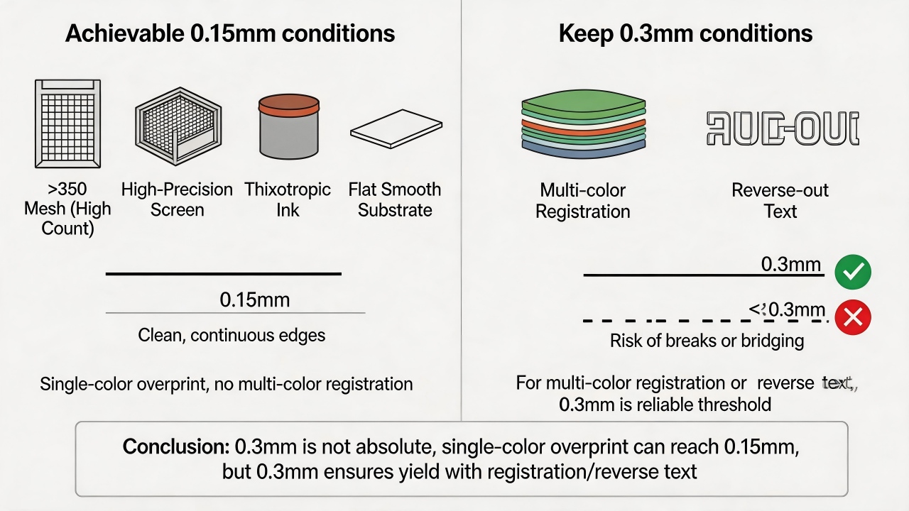
Under what conditions can 0.15mm be achieved? A minimum line width of 0.3mm is not an absolute limit—under the premise of overprinting (i.e., adjacent color blocks directly overlap without requiring precise registration with other colors) and in the absence of multi-color registration, single-color lines or solid edges can reach 0.15mm by selecting a high mesh count screen (e.g., above 350 mesh), employing a high-precision screen plate, using ink with good thixotropy, and printing onto a flat, smooth substrate. It must be clarified, however, that once multi-color registration or fine reversed-out text is involved, 0.3mm remains the reliable threshold for ensuring yield rate, and values below this are highly prone to line breakage or bridging due to registration deviation.
Why cannot printing be performed near drilled holes and irregularly cut edges? What is the safe distance?
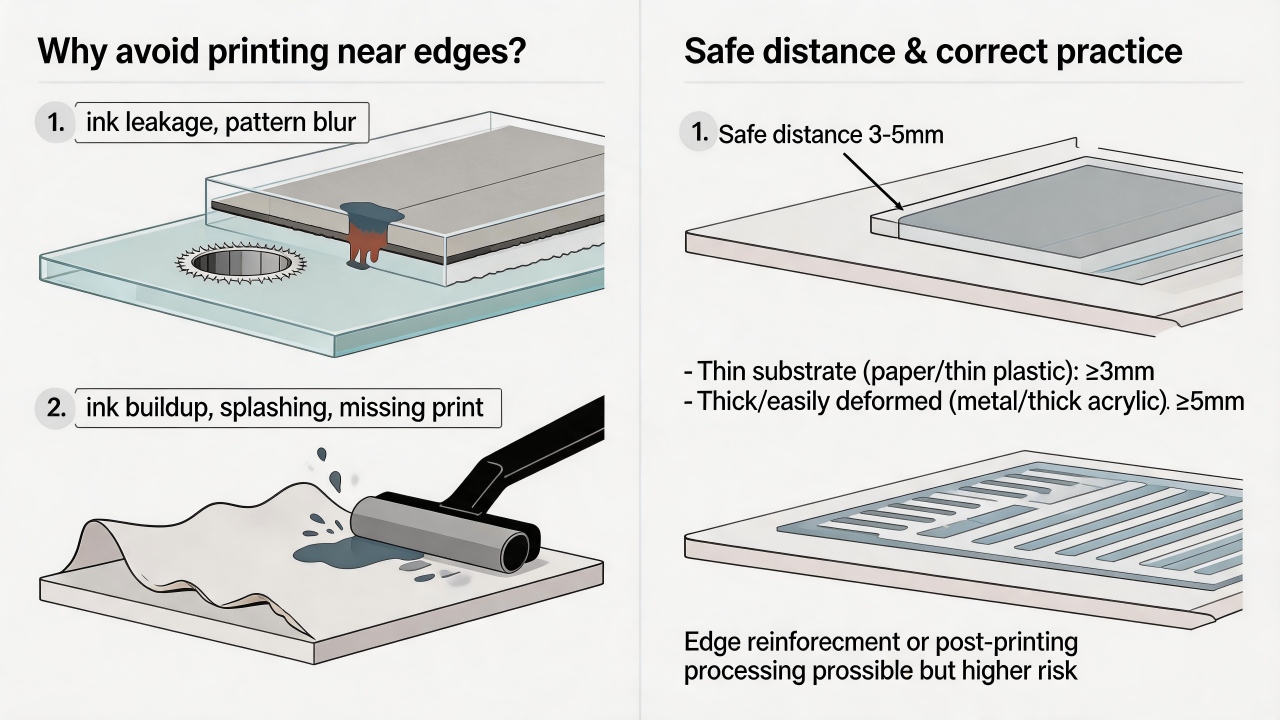
Printing cannot be performed near drilled holes and irregularly cut edges primarily because these areas present physical unevenness, stress concentration, or interference from subsequent processing: drilled hole edges are prone to burrs or deformation, preventing the screen from making uniform contact and leading to ink bleeding into the hole or pattern defects; irregularly cut edges may suffer from warping, debris, or fixture obstruction, causing uneven squeegee pressure that results in ink buildup, splattering, or missed prints. Furthermore, if cutting or drilling operations precede printing, the printed pattern may be damaged; if they follow printing, the positioning and fixturing may scratch the already printed ink layer. Therefore, to ensure acceptable yield rates, a safe distance of 3-5mm is typically maintained, depending on substrate thickness and edge flatness: for ordinary flat materials such as paper or thin plastic, 3mm suffices; for thicker or easily deformable materials such as metal or thick acrylic, retaining at least 5mm is recommended. In special circumstances where proximity to the edge is unavoidable, edge reinforcement, high-precision positioning, or post-printing processing strategies must be employed, though the associated risks increase significantly.
How much color difference can occur when printing white ink on ultra-clear glass versus ordinary clear glass?
When printing white ink on ultra-clear glass and ordinary clear glass, the color difference primarily originates from the inherent base color of the glass itself: ultra-clear glass (low-iron glass) has a light transmittance exceeding 91% and appears colorless or with a very faint bluish cyan tint, whereas ordinary clear glass (standard float glass) contains a higher iron content and exhibits a distinct greenish cast. After printing white ink, if the ink's opacity is insufficient, the background hue will transmit through the ink layer, causing the white to appear greenish or bluish. Typically, the ΔE color difference value ranges between 3 and 12, specifically depending on the ink's opacity, printed film thickness, and drying method: with high-opacity white ink (such as high-hide ceramic or glass-specific white) or when printed in two or more layers, ΔE ≈ 3–5, which may be imperceptible to the naked eye under normal lighting and requires comparison under a standard light source; with ordinary semi-transparent white ink or a single thin print layer, ΔE ≈ 8–12, and the naked eye can clearly discern that the white on ordinary clear glass appears greenish and duller, whereas the white on ultra-clear glass appears brighter and purer. Therefore, if extremely high white consistency is required (e.g., for white logos or premium appliance panels), it is recommended to select a high-opacity white ink and increase the ink film thickness, or to uniformly use ultra-clear glass as the substrate; before mass production, proofing and comparison are essential, with the actual measured color difference value serving as the final reference.
At what point does glass thickness tolerance begin to affect print uniformity?
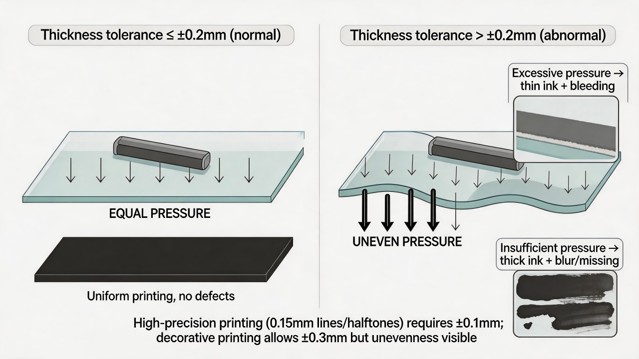
Glass thickness tolerance begins to noticeably affect screen printing uniformity when it exceeds ±0.2mm. The reason is that screen printing relies on a squeegee to transfer ink through the screen onto the glass surface, and squeegee pressure must remain consistent across the entire print area. When glass thickness varies by more than ±0.2mm, localized pressure changes significantly—in thicker areas, excessive pressure results in a thinner ink layer and edge bleeding, while in thinner areas, insufficient pressure leads to a thicker ink layer or even faint prints and missed prints. For high-precision printing (such as 0.15mm fine lines, halftone dots, or white ink requiring uniform coverage), tolerance should be controlled within ±0.1mm; for ordinary decorative printing, tolerance may be relaxed to ±0.3mm, though at this point visible ink unevenness may already appear. Therefore, before mass production, it is essential to measure glass thickness distribution or negotiate stricter tolerances with the supplier.
What design taboos does a registration tolerance of ±0.3mm imply in multi-color printing?
In multi-color printing, a registration tolerance of ±0.3mm means that the relative position between different colors may deviate by up to 0.3mm on each print run. While this value may seem small, it constitutes a rather strict constraint in actual design practice. Designers must understand that any area requiring precise edge alignment between different colors—without overlap or gap—is susceptible to noticeable misregistration. The ±0.3mm tolerance is not an "ideal-state precision" but rather an unavoidable range of variation inherent in the production process, resulting from factors such as screen stretch, squeegee pressure, and thermal expansion or contraction of the substrate. Therefore, design allowances must be made accordingly.
Specifically, the following design elements or approaches should be regarded as taboos:
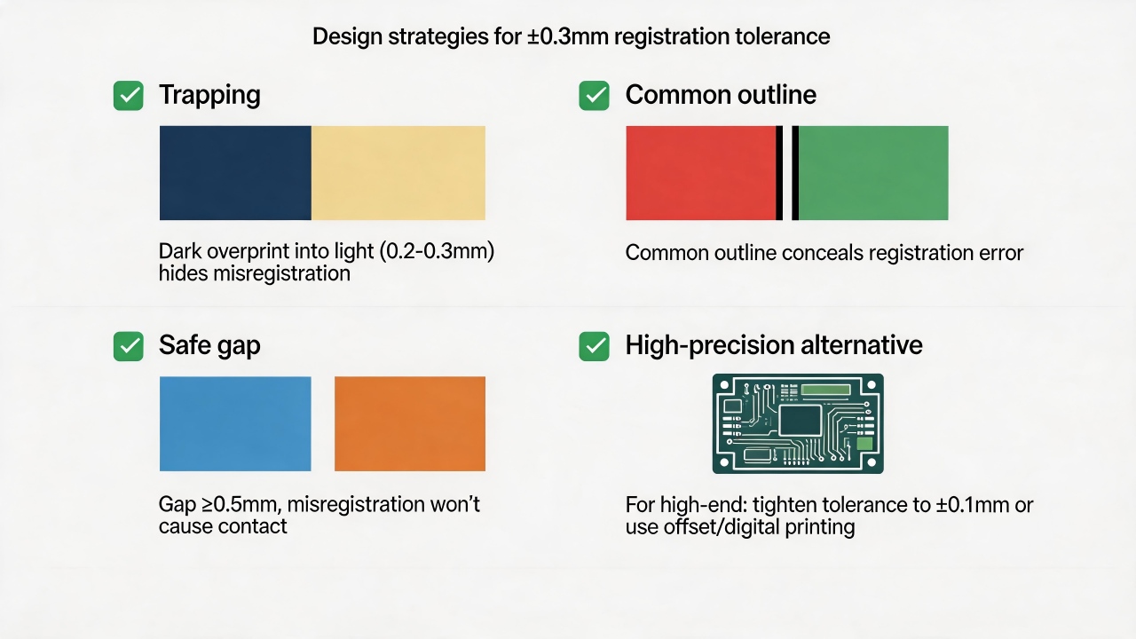
First, adjacent color areas that "butt" or have zero clearance. If two color blocks sit flush against each other with neither a gap nor an overlap, the tolerance will produce either a variable-width gap exposing the substrate or an overlapping dark line. For instance, a red circle flush against a blue square may theoretically share a boundary, but in actual printing the red may shift 0.2mm left while the blue shifts 0.1mm right, resulting in a 0.3mm gap that reveals the white substrate. Design should avoid such hard butting; instead, one color should be slightly expanded into the other (trapping, typically by 0.2–0.3mm), or a safe gap of at least 0.5mm (such as a white background or black outline) should be left between colors.
Second, fine lines or very small text placed precisely at the boundary of two colors. For example, a 0.2mm white line bordered by yellow on the left and green on the right may, due to the ±0.3mm tolerance, be entirely swallowed by one color or shifted into the other, resulting in uneven line width or complete disappearance. Similarly, small reversed-out text (e.g., below 2pt) positioned against the edge of another color is easily "eaten" by misregistration. The general recommendation is that any fine line (narrower than 0.5mm) or small text should not straddle the boundary between two colors; it is best printed in a single color or placed entirely within a single color block.
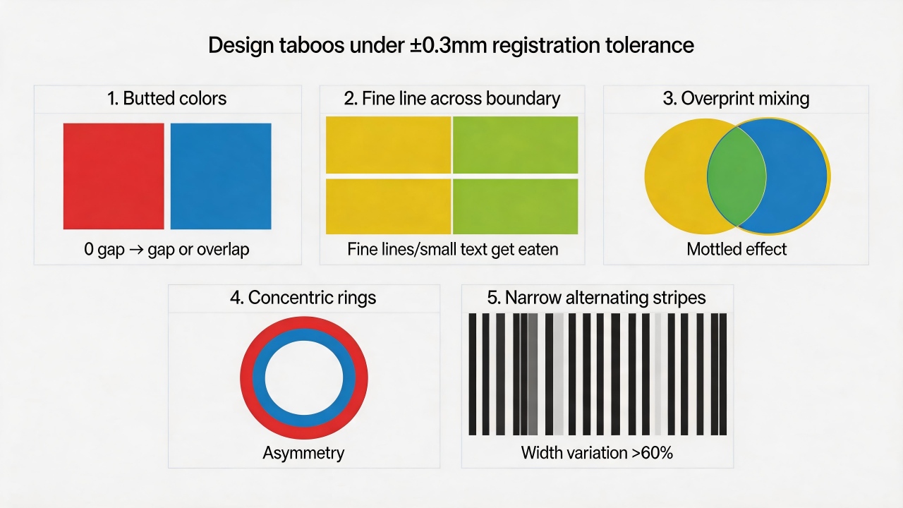
Third, areas that rely on overprinting to produce a third color. Some designs use yellow overprinted with blue to create green, but if registration deviates by ±0.3mm, the yellow and blue will only partially overlap, producing a mottled effect with yellow on one side, blue on the other, and green only in the middle, along with uneven edges. Unless a spot green is printed directly, large-area overprint color mixing should be avoided. For very small overprinted areas such as fine halftone dots, the tolerance will also cause dot misalignment, leading to moiré patterns or uneven color.
Fourth, concentric circles, parallel lines, or geometric patterns requiring strict centering. For instance, a ring design with a red outer circle and a blue inner circle separated by only a 0.2mm gap will, under a ±0.3mm tolerance, exhibit eccentricity, appearing comet-like or losing the gap on one side. Any multi-color design demanding precise centering or equal spacing requires a gap between colors substantially larger than 0.3mm (at least 0.8–1mm is recommended); otherwise, visual asymmetry will be strikingly apparent.
Fifth, extremely narrow alternating stripes of different colors. For example, alternating black and white stripes each only 0.5mm wide will see their widths vary by over 60% due to a ±0.3mm tolerance, and some stripes may be completely covered by adjacent colors. Such designs are virtually impossible to realize with multi-color screen printing and should be executed as single-color printing or via alternative processes such as digital printing.
How to address these issues? Designers should proactively employ trapping—allowing darker colors to slightly expand into lighter areas (typically by 0.2–0.3mm)—or add a common outline (such as a black keyline) between all adjacent color blocks to conceal registration errors. Alternatively, different colors can be designed as non-contacting, with a blank gap of at least 0.5mm left intentionally, making the error appear as part of the design. For products demanding high precision (e.g., electronic panels, fine trademarks), the registration tolerance should be specified as within ±0.1mm, or a higher-precision process such as offset printing or digital printing should be adopted.
In summary, a ±0.3mm tolerance requires a forgiving design approach—do not expect any boundaries to align perfectly; instead, proactively allow room for registration error to ensure the quality of the finished product.
Ink Selection and Durability
Where lies the "service life watershed" between ceramic inks and organic inks?
The most fundamental "service life watershed" between ceramic inks and organic inks resides in the entirely different mechanisms by which they form adhesion. Ceramic inks undergo chemical fusion with the substrate (such as glass or ceramic) through high-temperature sintering: the inorganic pigments and glass frit within the ink melt at elevated temperatures and form robust chemical bonds with the substrate surface, effectively "welding" the color into the substrate. Organic inks, in contrast, rely primarily on the physical adhesion of resin binders (e.g., acrylics, epoxies)—the cured resin encapsulates pigment particles and adheres them to the substrate without any chemical-level fusion. This intrinsic difference directly creates a vast performance chasm between the two in terms of weatherability, chemical resistance, abrasion resistance, and high-temperature tolerance.In terms of weatherability, ceramic inks, being composed of inorganic pigments and a vitreous matrix, inherently do not absorb ultraviolet radiation and exhibit exceptional resistance to UV aging. They resist fading and chalking even after years of outdoor exposure and typically maintain performance without noticeable degradation for over 15 years. Organic resins and certain organic pigments in organic inks, however, are sensitive to UV light; prolonged outdoor exposure leads to molecular chain scission or color decay, with noticeable fading, yellowing, or chalking generally occurring within 3–5 years—a clearly demarcated service life boundary.
With regard to chemical resistance, sintered ceramic ink forms a dense, glass-like structure that is virtually insoluble in any acid, alkali, or organic solvent, capable of withstanding extreme environments ranging from pH 1 to 13 and even enduring prolonged immersion in strong acids or alkalis. The resinous structure of organic inks, on the other hand, is readily swelled or dissolved by solvents such as alcohol, acetone, or toluene, and is also prone to hydrolysis or corrosion under strongly acidic or alkaline conditions, rendering them unsuitable for applications involving frequent chemical contact or cleaning and disinfection.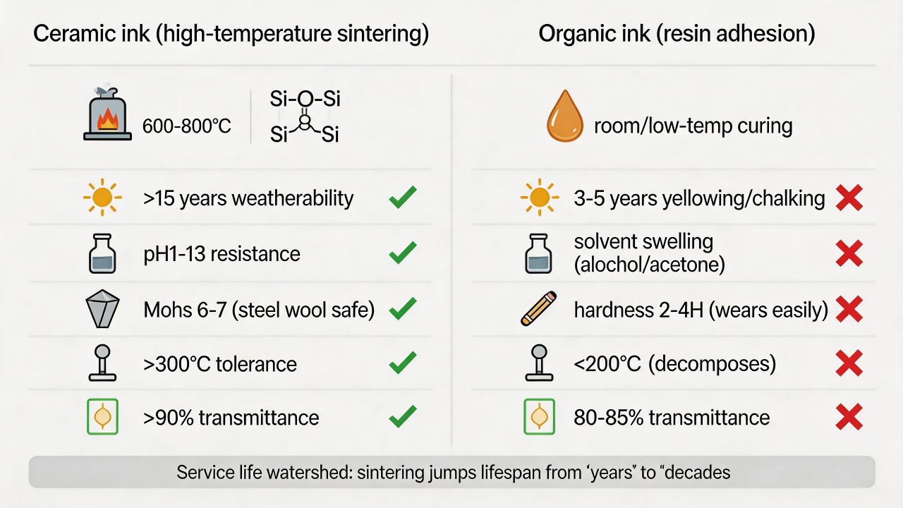 In mechanical abrasion resistance, ceramic ink fuses integrally with the substrate, achieving a Mohs hardness of 6–7 (comparable to that of glass) and demonstrating exceptional resistance to scratching and wear, even withstanding scouring with steel wool without damage. Organic inks depend on the mechanical strength of the resin itself, typically exhibiting a pencil hardness of only 2H–4H, and are susceptible to wear and delamination under repeated friction or grit impact.
High-temperature tolerance also constitutes a distinct watershed. Ceramic inks are themselves cured through sintering at temperatures of 600–800°C or even higher, and they can withstand prolonged exposure to temperatures exceeding 300°C, with certain specialty ceramic inks capable of enduring 800°C. The resins in organic inks are organic compounds that generally begin to decompose, carbonize, or discolor above 200°C, thus rendering them unsuitable for high-temperature environments.
Regarding the adhesion mechanism, ceramic inks bond to the substrate via chemical linkages (e.g., Si–O–Si), producing extremely strong adhesion that cannot be removed with ordinary adhesive tape; even if the substrate fractures, the ink layer remains intact. Organic inks rely primarily on physical interactions such as van der Waals forces or micro-mechanical interlocking, and under sustained humidity and heat, abrasion, or chemical exposure, adhesion may diminish or delamination may occur.
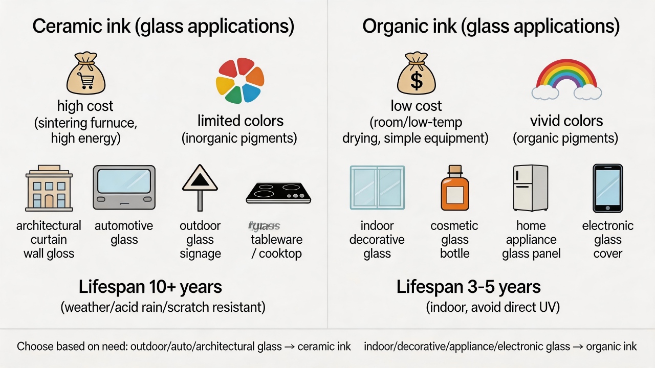
Cost and applicable scenarios also differ. Ceramic inks necessitate high-temperature sintering equipment, entail high energy consumption, and the inks themselves are more costly, with a relatively limited color palette due to the restricted variety of inorganic pigments. They are predominantly used in architectural exterior glass, automotive glass, ceramic tableware, outdoor signage, and other applications demanding an ultra-long service life (10+ years). Organic inks offer low cost, vibrant and abundant color options, and the ability to cure at room or low temperatures, making them suitable for interior decoration, plastic products, fast-moving consumer goods, packaging printing, and other products with relatively short life requirements (3–5 years) or rapid turnover cycles. Additionally, in terms of optical performance, high-quality sintered ceramic ink can achieve a light transmittance exceeding 90%, whereas organic inks, due to the inclusion of fillers and the inherent light absorption of the resin, typically exhibit transmittance reduced to 80–85%.
In summary, the key criterion demarcating the service life watershed is this: if a product must endure outdoor or harsh environments for more than 5 years, or if it requires resistance to high temperatures, strong acids and alkalis, or frequent abrasion, then sintered ceramic ink is the sole reliable choice; if the product is intended primarily for indoor use, has a service life requirement not exceeding 3–5 years, or prioritizes vibrant colors and low cost, organic ink is entirely adequate. There is no middle ground between the two—once the threshold of "high-temperature sintering" is crossed, service life leaps from the scale of "years" to that of "decades."
In mechanical abrasion resistance, ceramic ink fuses integrally with the substrate, achieving a Mohs hardness of 6–7 (comparable to that of glass) and demonstrating exceptional resistance to scratching and wear, even withstanding scouring with steel wool without damage. Organic inks depend on the mechanical strength of the resin itself, typically exhibiting a pencil hardness of only 2H–4H, and are susceptible to wear and delamination under repeated friction or grit impact.
High-temperature tolerance also constitutes a distinct watershed. Ceramic inks are themselves cured through sintering at temperatures of 600–800°C or even higher, and they can withstand prolonged exposure to temperatures exceeding 300°C, with certain specialty ceramic inks capable of enduring 800°C. The resins in organic inks are organic compounds that generally begin to decompose, carbonize, or discolor above 200°C, thus rendering them unsuitable for high-temperature environments.
Regarding the adhesion mechanism, ceramic inks bond to the substrate via chemical linkages (e.g., Si–O–Si), producing extremely strong adhesion that cannot be removed with ordinary adhesive tape; even if the substrate fractures, the ink layer remains intact. Organic inks rely primarily on physical interactions such as van der Waals forces or micro-mechanical interlocking, and under sustained humidity and heat, abrasion, or chemical exposure, adhesion may diminish or delamination may occur.
Cost and applicable scenarios also differ. Ceramic inks necessitate high-temperature sintering equipment, entail high energy consumption, and the inks themselves are more costly, with a relatively limited color palette due to the restricted variety of inorganic pigments. They are predominantly used in architectural exterior glass, automotive glass, ceramic tableware, outdoor signage, and other applications demanding an ultra-long service life (10+ years). Organic inks offer low cost, vibrant and abundant color options, and the ability to cure at room or low temperatures, making them suitable for interior decoration, plastic products, fast-moving consumer goods, packaging printing, and other products with relatively short life requirements (3–5 years) or rapid turnover cycles. Additionally, in terms of optical performance, high-quality sintered ceramic ink can achieve a light transmittance exceeding 90%, whereas organic inks, due to the inclusion of fillers and the inherent light absorption of the resin, typically exhibit transmittance reduced to 80–85%.
In summary, the key criterion demarcating the service life watershed is this: if a product must endure outdoor or harsh environments for more than 5 years, or if it requires resistance to high temperatures, strong acids and alkalis, or frequent abrasion, then sintered ceramic ink is the sole reliable choice; if the product is intended primarily for indoor use, has a service life requirement not exceeding 3–5 years, or prioritizes vibrant colors and low cost, organic ink is entirely adequate. There is no middle ground between the two—once the threshold of "high-temperature sintering" is crossed, service life leaps from the scale of "years" to that of "decades."
After how long in outdoor use will organic inks inevitably show visible degradation?
There is no fixed "expiration date" for visible degradation of organic inks outdoors; it depends on various factors such as the type of ink, color, quality, ink film thickness, and the usage environment, and actual service life can range from a few weeks to several years. Generally speaking, fluorescent inks, which have the poorest lightfastness, may exhibit noticeable fading after just one to two weeks of outdoor exposure; water-based dye inks typically last only about a month; ordinary water-based inkjet inks degrade in roughly two to three months. Oil-based solvent inks (such as those used for standard vehicle wraps) can endure outdoors for approximately one year; high-quality organic pigments (e.g., Permanent Orange G) combined with good formulations can achieve a lifespan of one to two years; eco-solvent inks or latex inks usually maintain performance for around three years; hard solvent inks and UV-curable inks offer better weatherability, reaching three to five years. If high-quality screen printing inks are employed and the ink film is sufficiently thick, five years outdoors without significant fading is also attainable. Beyond the type of ink itself, color is also a critical factor in determining lifespan. Different colors inherently possess different weatherability—typically, black and cyan exhibit the best stability, whereas lighter or more vivid colors such as yellow and magenta are more susceptible to molecular breakdown under UV radiation and thus fade more rapidly.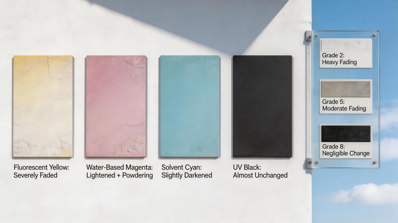 Pigment quality is equally crucial; the industry uses lightfastness ratings (1 to 8, with 8 being optimal) for evaluation, and pigments with high lightfastness ratings (7–8), such as phthalocyanine blue or Permanent Red F3RK, remain stable outdoors over the long term, while low-rated pigments (1–3) may undergo severe discoloration within weeks or months.
Furthermore, a thicker ink film equates to a more substantial pigment layer, enhancing resistance to UV and moisture erosion and thereby prolonging service life.
Compatibility between ink and substrate also affects outdoor durability. If the ink bonds poorly to the substrate, or if the substrate itself is prone to outdoor aging (e.g., certain epoxy resins may crack and chalk), the entire printed layer may prematurely delaminate or fail even if the ink quality is adequate.
Applying a protective layer to the printed surface is an effective means of extending lifespan—laminating or coating with a clear varnish acts as a "protective suit," substantially blocking UV radiation and physical abrasion, and can extend the outdoor life of organic inks to seven years or even longer.
Finally, the role of climatic conditions cannot be overlooked: high-intensity UV radiation (e.g., in plateau regions), high temperatures combined with high humidity, and airborne pollutants in industrial areas all accelerate the degradation process of inks, significantly curtailing actual service life. Therefore, to answer the question of "how long until degradation inevitably occurs," a comprehensive assessment must be made based on specific ink grade, color, thickness, protective measures, and installation location.
Pigment quality is equally crucial; the industry uses lightfastness ratings (1 to 8, with 8 being optimal) for evaluation, and pigments with high lightfastness ratings (7–8), such as phthalocyanine blue or Permanent Red F3RK, remain stable outdoors over the long term, while low-rated pigments (1–3) may undergo severe discoloration within weeks or months.
Furthermore, a thicker ink film equates to a more substantial pigment layer, enhancing resistance to UV and moisture erosion and thereby prolonging service life.
Compatibility between ink and substrate also affects outdoor durability. If the ink bonds poorly to the substrate, or if the substrate itself is prone to outdoor aging (e.g., certain epoxy resins may crack and chalk), the entire printed layer may prematurely delaminate or fail even if the ink quality is adequate.
Applying a protective layer to the printed surface is an effective means of extending lifespan—laminating or coating with a clear varnish acts as a "protective suit," substantially blocking UV radiation and physical abrasion, and can extend the outdoor life of organic inks to seven years or even longer.
Finally, the role of climatic conditions cannot be overlooked: high-intensity UV radiation (e.g., in plateau regions), high temperatures combined with high humidity, and airborne pollutants in industrial areas all accelerate the degradation process of inks, significantly curtailing actual service life. Therefore, to answer the question of "how long until degradation inevitably occurs," a comprehensive assessment must be made based on specific ink grade, color, thickness, protective measures, and installation location.Why must ceramic ink be used for printed patterns on oven door panels?
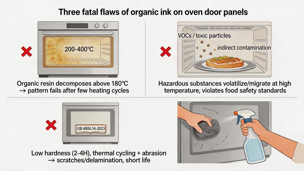
Printed patterns on oven door panels must use ceramic ink primarily because it simultaneously meets the three extremely demanding requirements of high-temperature resistance, food safety, and physical durability, whereas conventional organic inks exhibit fatal deficiencies in all three aspects.
First, the internal temperature of an oven during normal use can reach 200–300°C, and in self-cleaning mode temperatures may exceed 400°C—an environment that poses a severe challenge to any organic material. The organic pigments and resins in conventional inks have poor heat resistance, typically beginning to decompose, yellow, or fade around 180°C, and after just a few high-temperature cycles the pattern becomes blurred or disappears entirely. Ceramic ink, by contrast, is composed of inorganic pigments and glass frit, and its curing process requires high-temperature sintering above 600°C, after which it forms a stable, glassy inorganic layer capable of withstanding 400°C or higher over the long term without any change, keeping the pattern clear and vivid. Second, food safety is a core consideration that must be addressed in oven door panel printing. Although the oven door panel is not a surface that comes into direct contact with food, under high-temperature operating conditions, harmful substances (such as heavy metals, volatile organic compounds, and plasticizers) present in conventional organic inks used on the inner side of the door panel may volatilize or migrate into the oven's interior air, thereby indirectly contaminating food. China's "National Food Safety Standard—Inks for Food Contact Materials and Articles" (GB 4806.14-2023) imposes strict restrictions on such applications. After high-temperature sintering, ceramic ink forms a glass-like inorganic structure that is extremely stable and does not release any hazardous substances. High-quality ceramic inks are also free of heavy metals such as lead and cadmium, ensuring food safety at the source. It can be said that ceramic ink "fuses" the pattern into the glass surface, achieving physical-level safety isolation.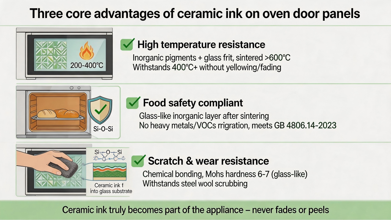 Third, oven door panels require frequent cleaning in daily use, often with abrasive cleaners and rough cloths or sponges. Conventional inks rely on the physical adhesion of resins to cling to the glass surface, exhibiting low hardness and poor abrasion resistance; after several cycles of thermal expansion and contraction coupled with repeated scrubbing, they are prone to scratching, peeling, or complete delamination. Ceramic ink, through high-temperature sintering, forms a chemical bond with the glass surface—the two become integral, yielding extremely strong adhesion that will not fail even under a cross-cut test using 3M tape. Its surface Mohs hardness can reach 6–7, comparable to that of glass itself, making it highly scratch-resistant, and the pattern remains intact even after prolonged scrubbing with steel wool or abrasive cleaners. Furthermore, ceramic ink resists corrosion from acids, alkalis, and various chemical cleaners, and will not be damaged by contact with vinegar, lemon juice, grease, or alkaline detergents.
From the perspectives of environmental friendliness and long-term reliability, ceramic ink also offers distinct advantages. Its production process generates extremely low emissions of VOCs (volatile organic compounds), making it more environmentally friendly than many traditional solvent-based inks. At the end of its service life, a glass door panel printed with ceramic ink will not release hazardous substances during recycling due to ink degradation.
In summary, for a specialized application such as an oven door panel that must endure sustained high temperatures, frequent cleaning, and proximity to a food environment, the "lifespan countdown" for conventional organic ink begins the moment the oven first heats up, whereas ceramic ink truly becomes "part of the appliance" precisely after high-temperature sintering is completed—hence it is the only reliable choice.
Third, oven door panels require frequent cleaning in daily use, often with abrasive cleaners and rough cloths or sponges. Conventional inks rely on the physical adhesion of resins to cling to the glass surface, exhibiting low hardness and poor abrasion resistance; after several cycles of thermal expansion and contraction coupled with repeated scrubbing, they are prone to scratching, peeling, or complete delamination. Ceramic ink, through high-temperature sintering, forms a chemical bond with the glass surface—the two become integral, yielding extremely strong adhesion that will not fail even under a cross-cut test using 3M tape. Its surface Mohs hardness can reach 6–7, comparable to that of glass itself, making it highly scratch-resistant, and the pattern remains intact even after prolonged scrubbing with steel wool or abrasive cleaners. Furthermore, ceramic ink resists corrosion from acids, alkalis, and various chemical cleaners, and will not be damaged by contact with vinegar, lemon juice, grease, or alkaline detergents.
From the perspectives of environmental friendliness and long-term reliability, ceramic ink also offers distinct advantages. Its production process generates extremely low emissions of VOCs (volatile organic compounds), making it more environmentally friendly than many traditional solvent-based inks. At the end of its service life, a glass door panel printed with ceramic ink will not release hazardous substances during recycling due to ink degradation.
In summary, for a specialized application such as an oven door panel that must endure sustained high temperatures, frequent cleaning, and proximity to a food environment, the "lifespan countdown" for conventional organic ink begins the moment the oven first heats up, whereas ceramic ink truly becomes "part of the appliance" precisely after high-temperature sintering is completed—hence it is the only reliable choice.How many times the cost of ordinary colors does metallic color (gold, silver, platinum) printing entail, and is it worthwhile?
In glass screen printing, the cost of metallic colors (gold, silver, platinum) is typically 3 to 5 times that of ordinary colors, with the exact multiple depending on the ink type, metal powder content, and print area. Ordinary glass colorants use inorganic pigments or ceramic pigments with relatively manageable costs, whereas metallic inks require the addition of high proportions of metal pigments such as copper-zinc powder, aluminum powder, platinum powder, or imitation gold powder, the raw material prices of which far exceed those of ordinary inorganic pigments. To achieve a mirror-like luster after glass sintering, the metal pigment loading usually reaches 40% to 60% of the total ink solids, which is 2 to 3 times that of ordinary colorants. Moreover, metallic inks have larger particle sizes, imposing higher demands on screen mesh count and tension, often necessitating specially customized screens and thicker emulsion layers, thereby increasing plate-making costs and printing difficulty. During sintering, metallic colors are also more sensitive to kiln temperature profiles, and the rejection rate may be 10% to 15% higher than that of ordinary colors. Cumulatively, these factors raise the unit comprehensive cost of metallic glass screen printing to 2 to 5 times that of ordinary colors, and even higher for large-area solid coverage printing.Is it then worthwhile to use metallic screen printing on glass? This depends entirely on the positioning and market objectives of the glass product. For ordinary household glassware (e.g., common drinking glasses, condiment bottles, budget glass jars), the cost increase from metallic colors is difficult to offset through higher selling prices and is generally not worthwhile. However, for mid-range to high-end glass products, the value of metallic colors is highly evident. For instance, on premium liquor bottles (brandy, whiskey), perfume bottles, cosmetic packaging bottles, luxury home decor glass (such as mirrored feature walls, art glass ornaments), and glass cover panels for high-end electronic products (e.g., metallic logos on certain mobile phone backs), the use of gold, silver, or platinum screen printing can instantly elevate the product's sense of luxury and refinement, making glass items stand out on the shelf. After sintering, metallic colors on glass possess permanent resistance to scratching, acids and alkalis, and high temperatures—a quality of "coexisting with the glass" that inherently conveys superior quality and enduring value.
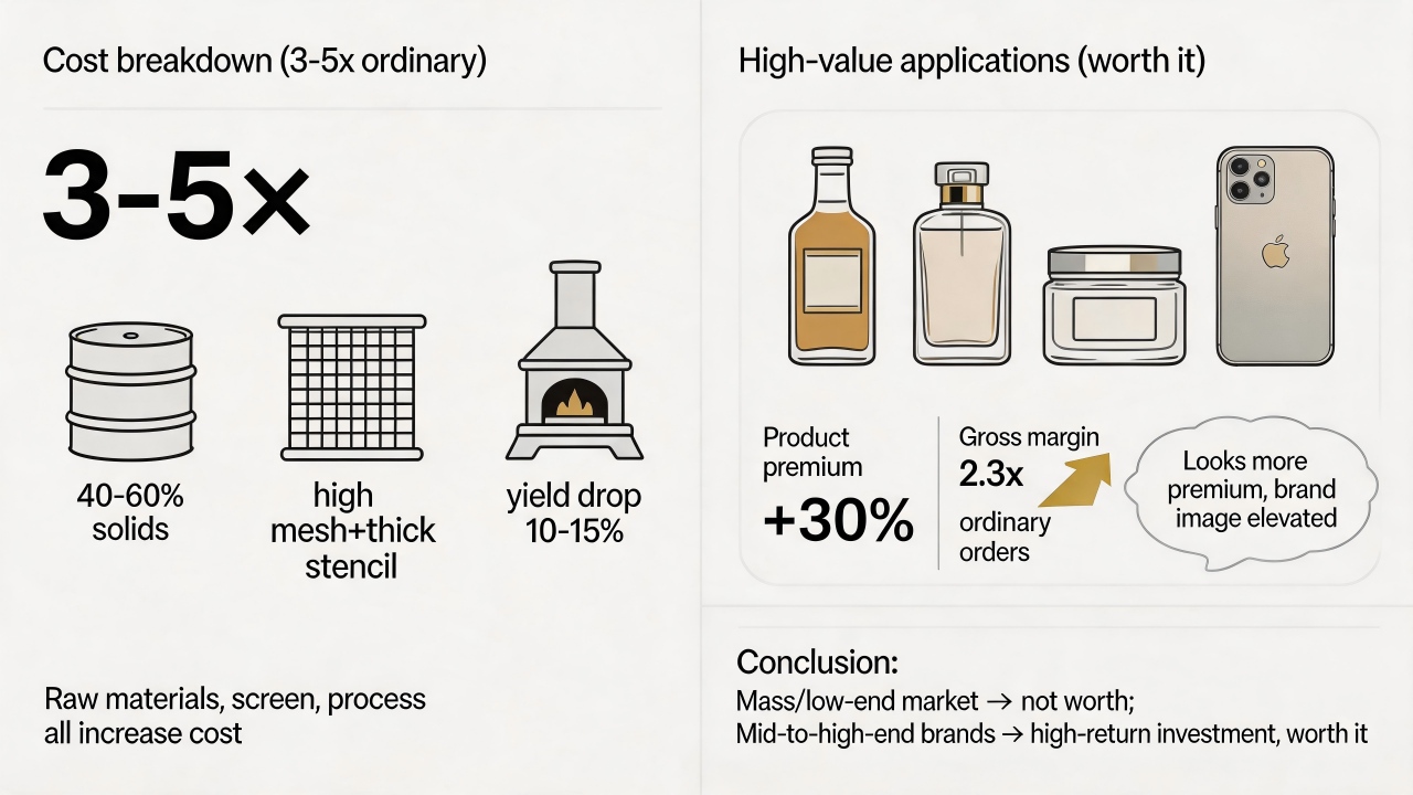 In a real-world case, a well-known baijiu brand replaced the ordinary white logo on its bottle with gold screen printing and saw a product premium enhancement of over 30%, with consumer feedback indicating it "looked more premium." Similarly, for glass packaging factories serving luxury brands, gross profit margins on metallic print orders are 2 to 3 times higher than those on ordinary color orders. Therefore, if your glass product targets the mass market or low-price competition, the cost pressure of metallic screen printing outweighs the benefits and is not recommended; but if the product is aimed at the mid-to-high-end market and seeks brand image elevation and visual differentiation, metallic printing is a high-return investment that not only supports higher selling prices but also reinforces the brand's premium perception among consumers.
How can the uniformity of light transmittance be controlled when using semi-transparent ink for backlighting?
The uniformity of light transmittance when using semi-transparent ink for backlighting can be precisely controlled, and the key lies in establishing a comprehensive management system that spans ink selection, screen preparation, printing processes, and quality inspection. The core principle for achieving uniform light transmission is to eliminate all factors that may cause uneven light scattering, ensuring that the ink film thickness and density remain entirely consistent across the entire printed area. The intrinsic quality of the ink itself is fundamental to achieving uniform light transmittance. Pigment fineness is a critical parameter, as the particle size of pigments in the ink directly affects light scattering behavior. If particles are excessively large or non-uniform, uneven diffuse reflection will occur when light passes through, resulting in visually perceptible brightness variations. Experience indicates that controlling ink fineness below 5-10 microns is a basic requirement for ensuring uniform light transmittance. At the same time, attention must be paid to ink leveling properties. Inks with good leveling characteristics naturally form a smooth, flat ink film after printing, avoiding defects such as orange peel or craters caused by uneven surface tension, which is a prerequisite for ensuring that light transmission is free of visual disturbances. High-quality inks typically possess excellent leveling properties. Every detail of the printing process is critically important. Ink film thickness must be precisely controlled, as light transmittance is directly related to film thickness. In the field of glass screen printing, a common technical specification is to precisely control the thickness of semi-transparent ink within the range of 8-15 microns to achieve customized light transmittance between 10% and 40%, thereby avoiding show-through or uneven halos. For colors with weak hiding power, such as white, multiple print passes may be necessary to increase film thickness and achieve uniform coverage. Printing speed must remain stable, as inconsistent speed directly leads to uneven ink film thickness; maintaining highly consistent printing speed and squeegee pressure is a prerequisite for ensuring film uniformity.What are the minimum requirements for printing on medical devices that must withstand alcohol wiping?
The minimum requirements for printing on medical devices that must withstand alcohol wiping are not a simple numerical value but rather a comprehensive system spanning material selection to production validation. In simple terms, it means ensuring that the printed pattern remains clear, intact, and free from color loss after repeated disinfection with alcohol. First, the printing must comply with medical industry regulations and biocompatibility requirements—that is, the ink must be safe and harmless to the human body. Inks used on medical devices, especially those that may come into direct or indirect contact with skin, must pass a series of biological tests, such as cytotoxicity testing, skin sensitization and irritation testing, typically referenced against the ISO 10993 series of standards. At the same time, the ink must be free of hazardous heavy metals and comply with environmental regulations such as RoHS and REACH. Many professional medical-grade inks clearly state compliance with these requirements in their product documentation. Furthermore, standards such as ISO 15223-1 are specifically used to verify that markings on products like syringes remain intact after alcohol wiping, and these should be considered when selecting inks.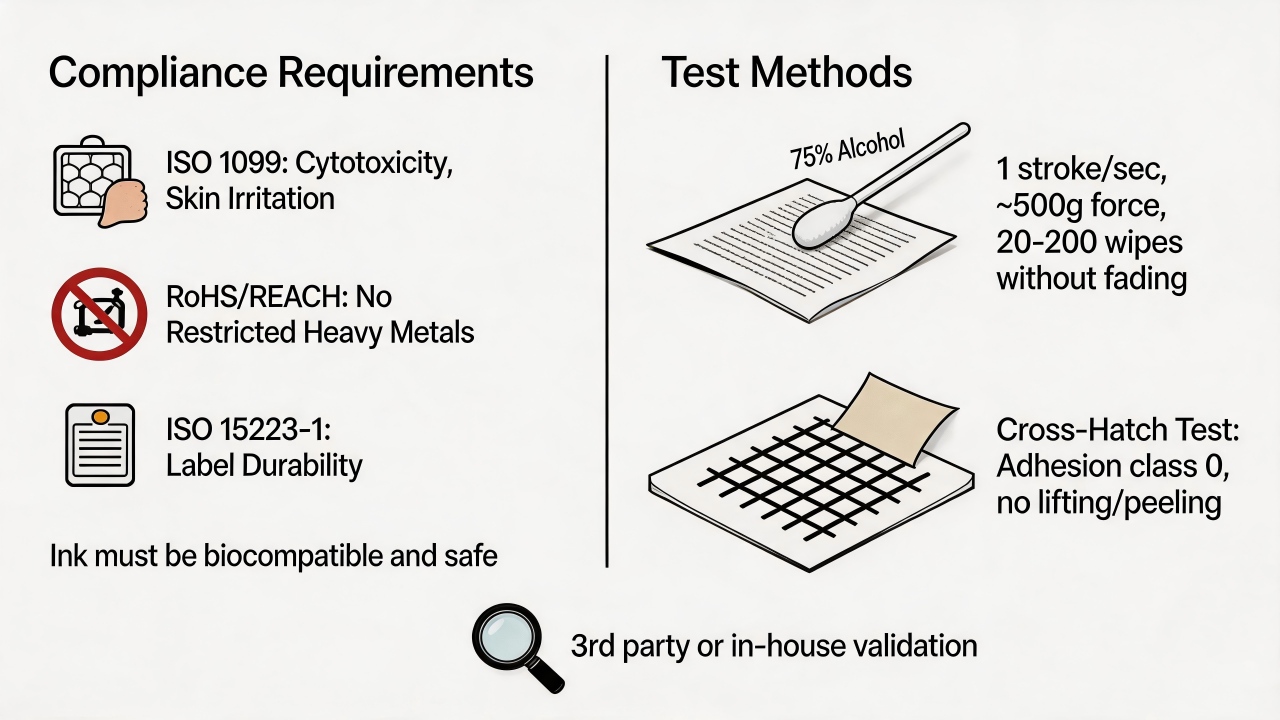 Regarding "how many alcohol wipes it can withstand," this is the most critical hard metric. According to conventional test methods (e.g., using a cotton swab saturated with 75% medical alcohol and rubbing back and forth at approximately one stroke per second), general medical devices are typically required to withstand 20 to 50 wipes. However, for devices requiring frequent, high-intensity disinfection (e.g., surgical instruments, buttons on patient monitors), the requirements are considerably more stringent, usually reaching 150 wipes or more, with some manufacturers' internal standards reaching as high as 200 wipes.
In addition to alcohol wipe resistance, medical device printing must meet other important requirements: adhesion must achieve the highest rating (cross-hatch cut followed by tape pull with no edge lifting or delamination), good abrasion resistance (no color loss from daily friction), and the ability to withstand processes such as high-temperature and high-pressure sterilization while resisting degradation from chemicals like isopropyl alcohol and cleaning agents.
So how should verification and selection be conducted? The most reliable approach is to engage a third-party testing organization to test the final product. A preliminary evaluation can also be performed in-house: use a cotton swab saturated with 75% alcohol and rub the printed surface back and forth with approximately 500 grams of force for the specified number of cycles, observing whether the pattern detaches, blurs, or changes color; then use a cross-hatch cutter to score a small grid, apply tape, and peel it off to observe ink loss. At the same time, carefully review the ink supplier's product data sheet to check the stated "alcohol resistance" performance and relevant certifications (e.g., RoHS). If the device requires sterilization, it is also necessary to confirm whether the ink can withstand that specific sterilization method.
Every step from design to production is critical. Selecting the correct ink type is key: two-component inks (requiring mixing with a hardener) cure via chemical reaction, offering the strongest chemical resistance and adhesion, making them the preferred choice for high-intensity alcohol disinfection; one-component inks (curing by evaporation or UV) are more convenient to use but have comparatively weaker chemical resistance and are suitable for less demanding components. For certain specialty plastics (e.g., PP, PE) or specific processes (e.g., pad printing), dedicated alcohol-resistant inks are also available.
Regarding "how many alcohol wipes it can withstand," this is the most critical hard metric. According to conventional test methods (e.g., using a cotton swab saturated with 75% medical alcohol and rubbing back and forth at approximately one stroke per second), general medical devices are typically required to withstand 20 to 50 wipes. However, for devices requiring frequent, high-intensity disinfection (e.g., surgical instruments, buttons on patient monitors), the requirements are considerably more stringent, usually reaching 150 wipes or more, with some manufacturers' internal standards reaching as high as 200 wipes.
In addition to alcohol wipe resistance, medical device printing must meet other important requirements: adhesion must achieve the highest rating (cross-hatch cut followed by tape pull with no edge lifting or delamination), good abrasion resistance (no color loss from daily friction), and the ability to withstand processes such as high-temperature and high-pressure sterilization while resisting degradation from chemicals like isopropyl alcohol and cleaning agents.
So how should verification and selection be conducted? The most reliable approach is to engage a third-party testing organization to test the final product. A preliminary evaluation can also be performed in-house: use a cotton swab saturated with 75% alcohol and rub the printed surface back and forth with approximately 500 grams of force for the specified number of cycles, observing whether the pattern detaches, blurs, or changes color; then use a cross-hatch cutter to score a small grid, apply tape, and peel it off to observe ink loss. At the same time, carefully review the ink supplier's product data sheet to check the stated "alcohol resistance" performance and relevant certifications (e.g., RoHS). If the device requires sterilization, it is also necessary to confirm whether the ink can withstand that specific sterilization method.
Every step from design to production is critical. Selecting the correct ink type is key: two-component inks (requiring mixing with a hardener) cure via chemical reaction, offering the strongest chemical resistance and adhesion, making them the preferred choice for high-intensity alcohol disinfection; one-component inks (curing by evaporation or UV) are more convenient to use but have comparatively weaker chemical resistance and are suitable for less demanding components. For certain specialty plastics (e.g., PP, PE) or specific processes (e.g., pad printing), dedicated alcohol-resistant inks are also available.
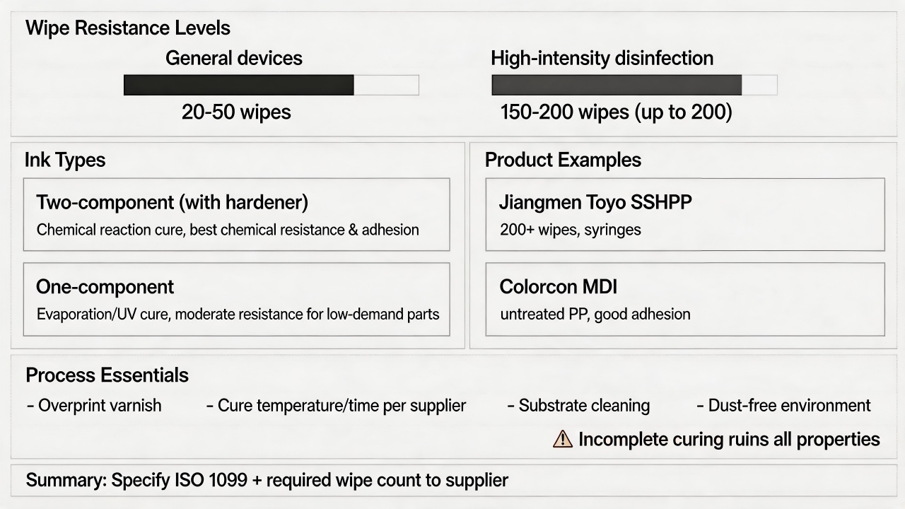 There are several proven products on the market that can serve as references. For example, Jiangmen Toyo's SSHPP series inks are specifically designed for syringe printing and can withstand over 200 alcohol wipes; Colorcon's MDI ink series is formulated for untreated polypropylene medical devices and offers excellent adhesion and alcohol resistance. Additionally, applying a protective overprint varnish or clear coat over the printed pattern can significantly enhance chemical and abrasion resistance. However, it is essential to strictly follow the ink supplier's recommended temperature and time for curing; incomplete curing will compromise all performance attributes. Whether the substrate surface is clean, whether the printing environment is dust-free, whether the ink is mixed correctly, and whether curing time is sufficient all directly determine final quality.
In summary, achieving alcohol wipe resistance for printing on medical devices is a systematic undertaking. The single most critical point is this: during the initial material selection phase, clearly inform the ink supplier: "I need to meet ISO 10993 biocompatibility requirements," and specify "must withstand XX wipes with 75% alcohol." This allows the supplier to recommend the most suitable product and preemptively avoid downstream issues.
There are several proven products on the market that can serve as references. For example, Jiangmen Toyo's SSHPP series inks are specifically designed for syringe printing and can withstand over 200 alcohol wipes; Colorcon's MDI ink series is formulated for untreated polypropylene medical devices and offers excellent adhesion and alcohol resistance. Additionally, applying a protective overprint varnish or clear coat over the printed pattern can significantly enhance chemical and abrasion resistance. However, it is essential to strictly follow the ink supplier's recommended temperature and time for curing; incomplete curing will compromise all performance attributes. Whether the substrate surface is clean, whether the printing environment is dust-free, whether the ink is mixed correctly, and whether curing time is sufficient all directly determine final quality.
In summary, achieving alcohol wipe resistance for printing on medical devices is a systematic undertaking. The single most critical point is this: during the initial material selection phase, clearly inform the ink supplier: "I need to meet ISO 10993 biocompatibility requirements," and specify "must withstand XX wipes with 75% alcohol." This allows the supplier to recommend the most suitable product and preemptively avoid downstream issues.Screen Making and Preparation
What specific printing defects will occur when screen tension drops from 20 N/cm to 15 N/cm?
When screen tension drops from 20 N/cm to 15 N/cm, although it may seem like a reduction of only 5 N, it triggers a chain reaction in actual printing that leads to a variety of defects. Lower tension means the screen becomes "loose," with reduced snap-off ability; after the squeegee passes, the screen cannot quickly separate from the substrate, directly affecting pattern precision and ink film quality.
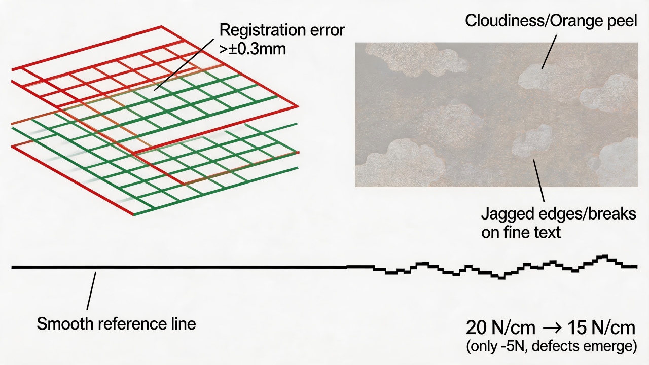 First, the most conspicuous defect is image distortion and misregistration. As screen tension decreases, the mesh becomes more prone to stretch and shift under squeegee pressure, causing the printed pattern to be larger than the original artwork or to exhibit shape distortion. Especially in multi-color printing, if the tensions of the first and second color screens are inconsistent, noticeable misalignment will occur—ranging from edge overlap or gaps in mild cases to a complete inability to align in severe instances. For registration requiring a tolerance within ±0.3 mm, a drop in tension often directly exceeds this range.
Second, ink film thickness becomes uneven, leading to obvious "cloudiness" or "orange peel." Under low tension, the gap between the screen and substrate (off-contact distance) is difficult to keep constant, and as the squeegee passes, the screen cannot uniformly contact and peel away, causing localized ink deposit to vary erratically. The result is that the printed surface has thick and thin areas, appearing as cloud-like patches or orange peel texture on solid backgrounds, severely compromising appearance consistency.
Third, the edges of fine lines develop jaggedness and burrs. A high-tension screen keeps the warp and weft threads in an orderly, taut state, yielding smooth line edges after printing. When tension drops and the mesh relaxes, the threads no longer remain straight, and the ink passing through the mesh openings is disturbed by the distorted threads, causing the printed lines to show pronounced stair-step jagged edges; fine text or patterns may even break or fail to print entirely.
Fourth, "poor wipe-off" or "sticking" occurs. With insufficient snap-off force under low tension, the screen cannot spring back quickly from the substrate surface after the squeegee stroke but instead "clings" to the ink, causing residual ink on the underside of the screen to be dragged during the next stroke, producing unintended smears or stains. In severe cases, the screen will stick firmly to the substrate, leading to printing interruption or product scrappage.
First, the most conspicuous defect is image distortion and misregistration. As screen tension decreases, the mesh becomes more prone to stretch and shift under squeegee pressure, causing the printed pattern to be larger than the original artwork or to exhibit shape distortion. Especially in multi-color printing, if the tensions of the first and second color screens are inconsistent, noticeable misalignment will occur—ranging from edge overlap or gaps in mild cases to a complete inability to align in severe instances. For registration requiring a tolerance within ±0.3 mm, a drop in tension often directly exceeds this range.
Second, ink film thickness becomes uneven, leading to obvious "cloudiness" or "orange peel." Under low tension, the gap between the screen and substrate (off-contact distance) is difficult to keep constant, and as the squeegee passes, the screen cannot uniformly contact and peel away, causing localized ink deposit to vary erratically. The result is that the printed surface has thick and thin areas, appearing as cloud-like patches or orange peel texture on solid backgrounds, severely compromising appearance consistency.
Third, the edges of fine lines develop jaggedness and burrs. A high-tension screen keeps the warp and weft threads in an orderly, taut state, yielding smooth line edges after printing. When tension drops and the mesh relaxes, the threads no longer remain straight, and the ink passing through the mesh openings is disturbed by the distorted threads, causing the printed lines to show pronounced stair-step jagged edges; fine text or patterns may even break or fail to print entirely.
Fourth, "poor wipe-off" or "sticking" occurs. With insufficient snap-off force under low tension, the screen cannot spring back quickly from the substrate surface after the squeegee stroke but instead "clings" to the ink, causing residual ink on the underside of the screen to be dragged during the next stroke, producing unintended smears or stains. In severe cases, the screen will stick firmly to the substrate, leading to printing interruption or product scrappage.
 Fifth, screen service life drops sharply. Reduced tension usually indicates that the screen has already fatigued or over-stretched. During repeated printing cycles, a low-tension screen is more susceptible to permanent deformation and may even tear from the frame edge. A screen originally capable of tens of thousands of prints may, at 15 N/cm, develop localized sagging or damage after only a few thousand cycles, resulting in frequent screen changes that increase cost and downtime.
Finally, the process becomes extremely sensitive to squeegee pressure and pneumatic parameters. A high-tension screen possesses a degree of "tolerance margin," whereas under low tension, a slightly higher squeegee pressure will over-deform the screen, elongating the pattern, while slightly lower pressure may result in insufficient ink deposit. Operators need to constantly fine-tune parameters, but stable control is often elusive, causing rejection rates to soar.
In summary, dropping from 20 N/cm to 15 N/cm does not represent a "still usable" condition but rather entry into a defect-prone zone. For most screen printing processes—especially those for glass, electronics, and medical products where precision and appearance are critical—15 N/cm is already at or below the acceptable lower limit, and it is generally recommended to maintain tension between 18 and 25 N/cm to achieve stable and reliable print quality.
Fifth, screen service life drops sharply. Reduced tension usually indicates that the screen has already fatigued or over-stretched. During repeated printing cycles, a low-tension screen is more susceptible to permanent deformation and may even tear from the frame edge. A screen originally capable of tens of thousands of prints may, at 15 N/cm, develop localized sagging or damage after only a few thousand cycles, resulting in frequent screen changes that increase cost and downtime.
Finally, the process becomes extremely sensitive to squeegee pressure and pneumatic parameters. A high-tension screen possesses a degree of "tolerance margin," whereas under low tension, a slightly higher squeegee pressure will over-deform the screen, elongating the pattern, while slightly lower pressure may result in insufficient ink deposit. Operators need to constantly fine-tune parameters, but stable control is often elusive, causing rejection rates to soar.
In summary, dropping from 20 N/cm to 15 N/cm does not represent a "still usable" condition but rather entry into a defect-prone zone. For most screen printing processes—especially those for glass, electronics, and medical products where precision and appearance are critical—15 N/cm is already at or below the acceptable lower limit, and it is generally recommended to maintain tension between 18 and 25 N/cm to achieve stable and reliable print quality.How large is the real gap in precision between stainless steel mesh and polyester mesh?
The real gap in precision between stainless steel mesh and polyester mesh is decisive and can be summarized as follows: polyester mesh is an excellent choice for high-precision printing, whereas stainless steel mesh is the unrivaled choice for micron-level ultra-fine printing. The difference between the two is primarily reflected in core parameters such as thread diameter, weave uniformity, tension retention capability, and minimum line width limits. Stainless steel as a material possesses extremely high strength and can be drawn into very fine wires, with wire diameters typically reaching 20 to 30 microns or even smaller; polyester fibers, by contrast, are limited by the material's physical properties and generally have coarser diameters, typically in the range of 30 to 50 microns or higher. Finer wires mean that a higher mesh count can be woven within the same area, thereby forming finer mesh openings—this is the physical foundation that enables stainless steel mesh to achieve ultra-fine printing.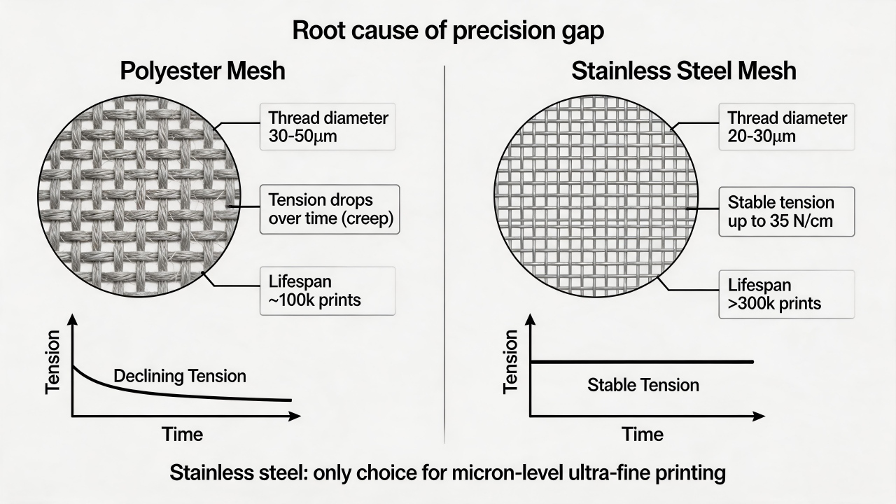 In terms of weave uniformity, stainless steel mesh likewise holds a distinct advantage. Through precision weaving processes, the mesh openings of stainless steel mesh are arranged with extreme regularity, with very low error rates in wire diameter and aperture, which allows ink to pass through the mesh evenly and controllably under the squeegee, ensuring straight and sharp edges on fine lines. Polyester mesh, while capable of achieving high weaving precision, is limited by the material's flexibility and thermal stability, and its uniformity after prolonged use is often inferior to that of stainless steel mesh.
In terms of tension retention capability, stainless steel mesh performs almost perfectly: its metallic nature means it does not exhibit creep, and it can maintain a stable tension of up to 35 N/cm or higher over the long term, preserving dimensional accuracy of the pattern even after hundreds of thousands of print cycles. Polyester mesh, however, exhibits creep behavior, with tension declining gradually as the number of print cycles increases, leading to image distortion and misregistration; its typical service life is approximately 100,000 cycles, whereas a stainless steel screen can last over 300,000 cycles.
These physical differences ultimately manifest in actual printing precision. In the field of glass screen printing, the precision requirements of different process steps also reflect the differences between the two types of mesh. For example, in the printing of conductive dots for LCD glass, 250-mesh stainless steel mesh is often selected, whereas for TN-type LCD edge seal adhesive printing, which has relatively lower precision requirements, 120T polyester mesh can be used. When high-precision silver lines need to be printed or products such as touch panels and mobile phone glass cover plates are being manufactured, high-tension, high-stability stainless steel composite screens are a necessary choice; similarly, for the production of high-specification, high-grade LCDs (such as FSTN and Color STN), stainless steel mesh should be used because it provides more stable tension and better precision and can be reclaimed and reused after stripping. In the extreme domain of stainless steel mesh, for instance, stainless steel screens used for printing silver lines can achieve mesh counts of 640, 500, and 400, enabling micron-level conductive line printing.
In actual production, polyester mesh is widely used in the glass printing field owing to its cost-effectiveness and sufficient precision for most requirements. For example, a glass factory using large polyester screens to print curtain wall patterns achieved ink adhesion of grade 5B, no fading in weatherability testing (1,000 hours of UV aging), and a consistent product yield rate above 99%. For markets such as automotive glass, architectural glass, and appliance glass, high-modulus, low-elongation polyester mesh has also been developed specifically for the glass screen printing industry, which, through special surface treatment technology, enhances dimensional stability, registration accuracy, and ink deposit controllability. However, the application of stainless steel mesh in the glass field also has specific limitations. For example, when gold color is to be printed on glass, stainless steel mesh is generally not recommended, because stainless steel can chemically react with gold ink, leading to printing defects.
In terms of weave uniformity, stainless steel mesh likewise holds a distinct advantage. Through precision weaving processes, the mesh openings of stainless steel mesh are arranged with extreme regularity, with very low error rates in wire diameter and aperture, which allows ink to pass through the mesh evenly and controllably under the squeegee, ensuring straight and sharp edges on fine lines. Polyester mesh, while capable of achieving high weaving precision, is limited by the material's flexibility and thermal stability, and its uniformity after prolonged use is often inferior to that of stainless steel mesh.
In terms of tension retention capability, stainless steel mesh performs almost perfectly: its metallic nature means it does not exhibit creep, and it can maintain a stable tension of up to 35 N/cm or higher over the long term, preserving dimensional accuracy of the pattern even after hundreds of thousands of print cycles. Polyester mesh, however, exhibits creep behavior, with tension declining gradually as the number of print cycles increases, leading to image distortion and misregistration; its typical service life is approximately 100,000 cycles, whereas a stainless steel screen can last over 300,000 cycles.
These physical differences ultimately manifest in actual printing precision. In the field of glass screen printing, the precision requirements of different process steps also reflect the differences between the two types of mesh. For example, in the printing of conductive dots for LCD glass, 250-mesh stainless steel mesh is often selected, whereas for TN-type LCD edge seal adhesive printing, which has relatively lower precision requirements, 120T polyester mesh can be used. When high-precision silver lines need to be printed or products such as touch panels and mobile phone glass cover plates are being manufactured, high-tension, high-stability stainless steel composite screens are a necessary choice; similarly, for the production of high-specification, high-grade LCDs (such as FSTN and Color STN), stainless steel mesh should be used because it provides more stable tension and better precision and can be reclaimed and reused after stripping. In the extreme domain of stainless steel mesh, for instance, stainless steel screens used for printing silver lines can achieve mesh counts of 640, 500, and 400, enabling micron-level conductive line printing.
In actual production, polyester mesh is widely used in the glass printing field owing to its cost-effectiveness and sufficient precision for most requirements. For example, a glass factory using large polyester screens to print curtain wall patterns achieved ink adhesion of grade 5B, no fading in weatherability testing (1,000 hours of UV aging), and a consistent product yield rate above 99%. For markets such as automotive glass, architectural glass, and appliance glass, high-modulus, low-elongation polyester mesh has also been developed specifically for the glass screen printing industry, which, through special surface treatment technology, enhances dimensional stability, registration accuracy, and ink deposit controllability. However, the application of stainless steel mesh in the glass field also has specific limitations. For example, when gold color is to be printed on glass, stainless steel mesh is generally not recommended, because stainless steel can chemically react with gold ink, leading to printing defects.
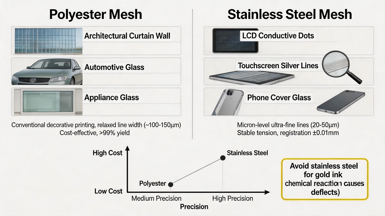 So, how does one choose in actual production? If your product requires printing extremely fine silver lines on glass, manufacturing high-precision capacitive touch panels or mobile phone cover plates, and pursuing micron-level accuracy and a very high yield rate, then stainless steel mesh is the only option. For most conventional glass printing needs—such as decorative patterns on architectural glass curtain walls or automotive glass, and appliance glass panels—where line width requirements are relatively relaxed, polyester mesh fully meets the requirements and offers lower cost and better cost performance. At the same time, to address the issue of tension decline in polyester mesh, higher-performance polyester fabrics such as those with high modulus and low elongation can be selected for improvement.
In summary, each type of mesh has its suitable application scenarios, and it is advisable to make a decision based on the product's minimum line width requirements and production budget, and, where necessary, to request samples from the supplier for actual testing.
So, how does one choose in actual production? If your product requires printing extremely fine silver lines on glass, manufacturing high-precision capacitive touch panels or mobile phone cover plates, and pursuing micron-level accuracy and a very high yield rate, then stainless steel mesh is the only option. For most conventional glass printing needs—such as decorative patterns on architectural glass curtain walls or automotive glass, and appliance glass panels—where line width requirements are relatively relaxed, polyester mesh fully meets the requirements and offers lower cost and better cost performance. At the same time, to address the issue of tension decline in polyester mesh, higher-performance polyester fabrics such as those with high modulus and low elongation can be selected for improvement.
In summary, each type of mesh has its suitable application scenarios, and it is advisable to make a decision based on the product's minimum line width requirements and production budget, and, where necessary, to request samples from the supplier for actual testing.Which is more suitable for high-precision logo printing: direct/indirect emulsion or capillary film?
For high-precision logo printing, capillary film is a superior choice over direct/indirect emulsion. The most fundamental difference between the two lies in the fact that capillary film forms a layer of uniform thickness and smooth surface on the screen through precision coating and capillary action, a process that fundamentally ensures outstanding accuracy. In contrast, direct/indirect emulsion requires manual or semi-automatic coating, and the film thickness and uniformity are highly dependent on the operator's experience and technique, making it difficult to achieve microscopic precision. This often results in uneven film thickness and edge jaggedness, compromising the reproduction fidelity of fine lines. In terms of image precision and resolution, capillary film offers a distinct advantage. Because the printing side of capillary film is exceptionally smooth, it effectively reduces ink scattering and jaggedness as ink passes through the mesh openings, making it particularly suitable for producing fine lines, small text, and halftone dots—hence it is the first choice for high-precision logo printing. The surface smoothness of direct/indirect emulsion after coating is comparatively poorer, especially during manual application, where the emulsion layer is prone to localized variations in thickness, leading to uneven line edges after development, and fine patterns may suffer from breaks or blurring.How significant is the impact of a 10% deviation in exposure time on line edge sharpness?
A 10% deviation in exposure time has a significant and non-negligible impact on line edge sharpness, manifesting as jaggedness, dimensional drift, and edge burrs. In screen making, there is an optimal exposure time; when the deviation is kept within ±10%, line edges can generally be kept straight and sharp, meeting the requirements of high-precision printing. Once this range is exceeded, the degradation in line quality becomes visibly apparent. When exposure time is insufficient (10% below the optimum), the photochemical reaction in the emulsion is incomplete, leaving the stencil layer under-cured. During subsequent development, the edges of the image areas, which should have been retained, are excessively washed away—like "softened walls"—resulting in pronounced jaggedness along the line edges. At the same time, the overall line becomes wider than the designed dimension. Furthermore, the under-cured emulsion bonds weakly to the mesh, leading to reduced print durability and a shorter screen life.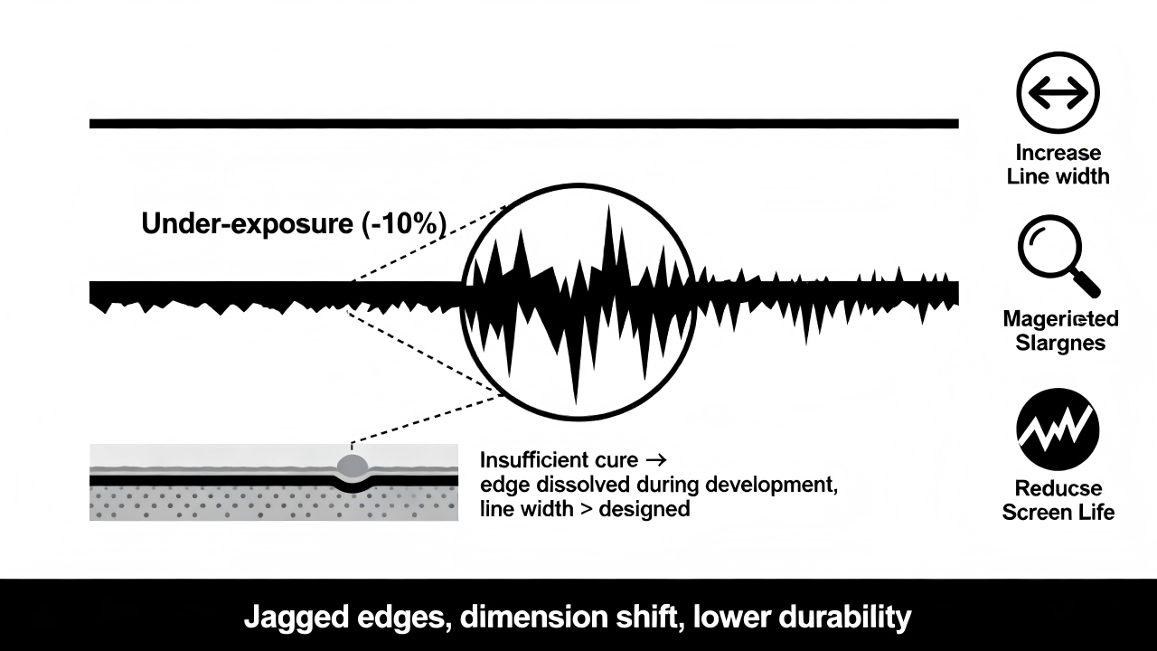 When exposure time is excessive (10% above the optimum), UV light scatters through the edges of the transparent areas of the film positive and penetrates into the emulsion regions that should have remained intact. This is akin to "burning" a portion of the image edge, causing fine burrs along the line edges after development, while the overall line becomes thinner than the designed dimension. Over-exposure can also leave a residue of emulsion in areas that should have washed out, causing mesh clogging and making development more difficult.
Therefore, a ±10% exposure deviation is generally regarded as the "golden tolerance" range for maintaining sharp line edges in high-precision work. In actual production, it is advisable to use an exposure calculator or a step test strip to determine the precise exposure parameters, keeping the deviation within 5% to ensure the edge sharpness and dimensional accuracy of fine lines. For high-precision logos with line widths below 0.1mm, even a 5% deviation in exposure time can cause a decline in edge quality, thus requiring even tighter process control.
When exposure time is excessive (10% above the optimum), UV light scatters through the edges of the transparent areas of the film positive and penetrates into the emulsion regions that should have remained intact. This is akin to "burning" a portion of the image edge, causing fine burrs along the line edges after development, while the overall line becomes thinner than the designed dimension. Over-exposure can also leave a residue of emulsion in areas that should have washed out, causing mesh clogging and making development more difficult.
Therefore, a ±10% exposure deviation is generally regarded as the "golden tolerance" range for maintaining sharp line edges in high-precision work. In actual production, it is advisable to use an exposure calculator or a step test strip to determine the precise exposure parameters, keeping the deviation within 5% to ensure the edge sharpness and dimensional accuracy of fine lines. For high-precision logos with line widths below 0.1mm, even a 5% deviation in exposure time can cause a decline in edge quality, thus requiring even tighter process control.Printing Process Control
What typical printing defects can result from incorrect squeegee hardness selection?
Incorrect squeegee hardness selection can lead to a series of typical printing defects that directly affect ink film thickness, line sharpness, and print consistency. Squeegee hardness is typically expressed in Shore A durometer, ranging from 55A to 95A, with different hardness levels suited to different ink types and printing precision requirements. When a squeegee is too hard or too soft, corresponding problems arise. If the chosen squeegee is too hard (e.g., above 90A for general printing other than fine lines), the squeegee edge cannot conform to the minute undulations of the screen and substrate surface, resulting in insufficiently close contact between the screen and the substrate. This causes uneven ink deposit, manifesting as noticeable "cloudiness" or "orange peel" — areas of thicker and thinner ink film, especially conspicuous on solid backgrounds. At the same time, an overly hard squeegee accelerates screen wear, shortening screen life, and may even produce scratches on hard substrates like glass. For fine line printing, although a hard squeegee is theoretically more favorable, improper matching will, due to a lack of sufficient flex, fail to cleanly "shear" the ink from the mesh, leading to edge burrs or ink spattering on the lines.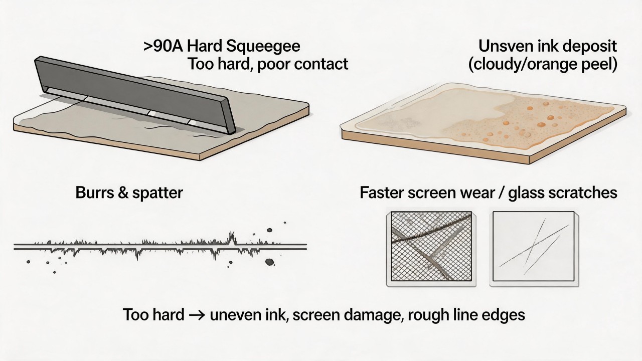 If the chosen squeegee is too soft (e.g., 55A to 65A for high-precision printing), the squeegee edge is prone to bending and deformation during the print stroke, failing to extrude ink uniformly through the mesh openings. This results in excessive ink deposit and a thicker ink film; fine lines noticeably "gain weight," becoming wider than the designed dimension by 0.1 mm or more, causing dimensional accuracy failure. Moreover, after the print stroke, a soft squeegee cannot wipe the residual ink from the screen cleanly, leaving trailing or hazy smears in non-image areas, a defect known as "poor wipe-off." In multi-color printing, the uneven ink film thickness and pattern distortion caused by a soft squeegee will also lead to misregistration, where the edges between different colors cannot align precisely. Additionally, soft squeegees wear very quickly, with the edge rapidly becoming rounded and blunt, necessitating frequent replacement and impacting production efficiency.
Therefore, selecting the correct squeegee hardness requires a comprehensive assessment based on the fineness of the printed pattern and the ink type. For high-precision logos, fine lines, and halftone dot printing, a harder squeegee (75A to 85A) is generally recommended to ensure line sharpness and dimensional stability; for large solid background areas and thick-film printing requiring high hiding power, a medium-hardness squeegee (65A to 75A) can be used to achieve sufficient ink film thickness; soft squeegees are only considered for rough surfaces or special effects that demand an extremely thick ink layer. In actual production, it is advisable to verify squeegee hardness suitability through test prints, observing whether line edges are sharp, whether the ink film is uniform, and whether any trailing smears exist, in order to determine the optimal parameters.
If the chosen squeegee is too soft (e.g., 55A to 65A for high-precision printing), the squeegee edge is prone to bending and deformation during the print stroke, failing to extrude ink uniformly through the mesh openings. This results in excessive ink deposit and a thicker ink film; fine lines noticeably "gain weight," becoming wider than the designed dimension by 0.1 mm or more, causing dimensional accuracy failure. Moreover, after the print stroke, a soft squeegee cannot wipe the residual ink from the screen cleanly, leaving trailing or hazy smears in non-image areas, a defect known as "poor wipe-off." In multi-color printing, the uneven ink film thickness and pattern distortion caused by a soft squeegee will also lead to misregistration, where the edges between different colors cannot align precisely. Additionally, soft squeegees wear very quickly, with the edge rapidly becoming rounded and blunt, necessitating frequent replacement and impacting production efficiency.
Therefore, selecting the correct squeegee hardness requires a comprehensive assessment based on the fineness of the printed pattern and the ink type. For high-precision logos, fine lines, and halftone dot printing, a harder squeegee (75A to 85A) is generally recommended to ensure line sharpness and dimensional stability; for large solid background areas and thick-film printing requiring high hiding power, a medium-hardness squeegee (65A to 75A) can be used to achieve sufficient ink film thickness; soft squeegees are only considered for rough surfaces or special effects that demand an extremely thick ink layer. In actual production, it is advisable to verify squeegee hardness suitability through test prints, observing whether line edges are sharp, whether the ink film is uniform, and whether any trailing smears exist, in order to determine the optimal parameters.
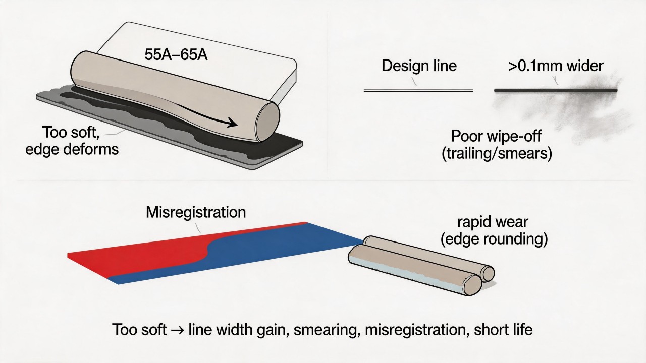
Why does increasing printing speed cause the ink film to become thinner, and how can this be compensated?
The fundamental reason why increasing printing speed causes the ink film to become thinner lies in changes to the rheological properties of the ink and the separation process between the screen and the substrate. When printing speed increases, the squeegee moves more rapidly across the screen, meaning the ink is subjected to shear force for a shorter period. Ink is a typical non-Newtonian fluid exhibiting shear-thinning behavior. During slow printing, the ink has ample time to be pressed by the squeegee into the mesh openings and to transfer smoothly from the openings onto the substrate. Once the speed is increased, the ink is pushed past by the squeegee before it can fully fill the mesh openings, resulting in a reduced amount of ink passing through the mesh per unit area and a naturally thinner ink film. At the same time, high-speed printing also affects the peeling process between the screen and the substrate. After printing is completed, the screen needs to snap off from the substrate surface, "breaking" the ink and leaving it on the substrate. When the speed is too high, this peeling process becomes unstable, the ink transfer efficiency declines, and some ink is carried back with the screen, further contributing to a thinner ink film.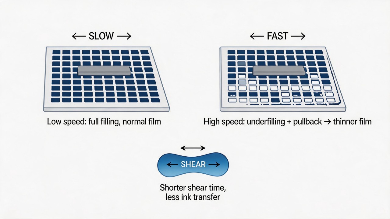 To compensate for the thinning of the ink film caused by increased printing speed, adjustments can be made in the following directions. First, appropriately reduce squeegee pressure. Many assume that higher speed requires more pressure, but in reality excessive pressure flattens the screen too much, deforming the mesh openings and further hindering ink passage. The correct approach is to slightly reduce squeegee pressure, allowing the squeegee to glide over the screen in a "lighter" manner and leaving more room for the ink to fill.
Second, select a softer squeegee. A softer squeegee (e.g., 65-70A) conforms better to the screen during high-speed printing, creating a wider print contact area, increasing ink compression time and throughput, thereby compensating for ink film thickness.
Third, adjust the viscosity of the ink. The ink viscosity can be appropriately reduced (e.g., by adding a small amount of thinner) so that the ink flows and fills the mesh openings more easily under high shear. However, care must be taken not to over-thin the ink, as this may cause line spread and blurred edges.
Fourth, increase the off-contact distance between the screen and the substrate. An appropriately increased off-contact distance enhances the screen's snap-off force, helping the ink to release better from the mesh openings onto the substrate during high-speed printing. However, excessive off-contact distance can affect pattern precision and requires balancing.
Fifth, use a screen with a lower mesh count or finer thread diameter. If the process permits, selecting a screen with larger mesh openings reduces the resistance to ink passage, preventing the ink film from becoming too thin during high-speed printing.
To compensate for the thinning of the ink film caused by increased printing speed, adjustments can be made in the following directions. First, appropriately reduce squeegee pressure. Many assume that higher speed requires more pressure, but in reality excessive pressure flattens the screen too much, deforming the mesh openings and further hindering ink passage. The correct approach is to slightly reduce squeegee pressure, allowing the squeegee to glide over the screen in a "lighter" manner and leaving more room for the ink to fill.
Second, select a softer squeegee. A softer squeegee (e.g., 65-70A) conforms better to the screen during high-speed printing, creating a wider print contact area, increasing ink compression time and throughput, thereby compensating for ink film thickness.
Third, adjust the viscosity of the ink. The ink viscosity can be appropriately reduced (e.g., by adding a small amount of thinner) so that the ink flows and fills the mesh openings more easily under high shear. However, care must be taken not to over-thin the ink, as this may cause line spread and blurred edges.
Fourth, increase the off-contact distance between the screen and the substrate. An appropriately increased off-contact distance enhances the screen's snap-off force, helping the ink to release better from the mesh openings onto the substrate during high-speed printing. However, excessive off-contact distance can affect pattern precision and requires balancing.
Fifth, use a screen with a lower mesh count or finer thread diameter. If the process permits, selecting a screen with larger mesh openings reduces the resistance to ink passage, preventing the ink film from becoming too thin during high-speed printing.
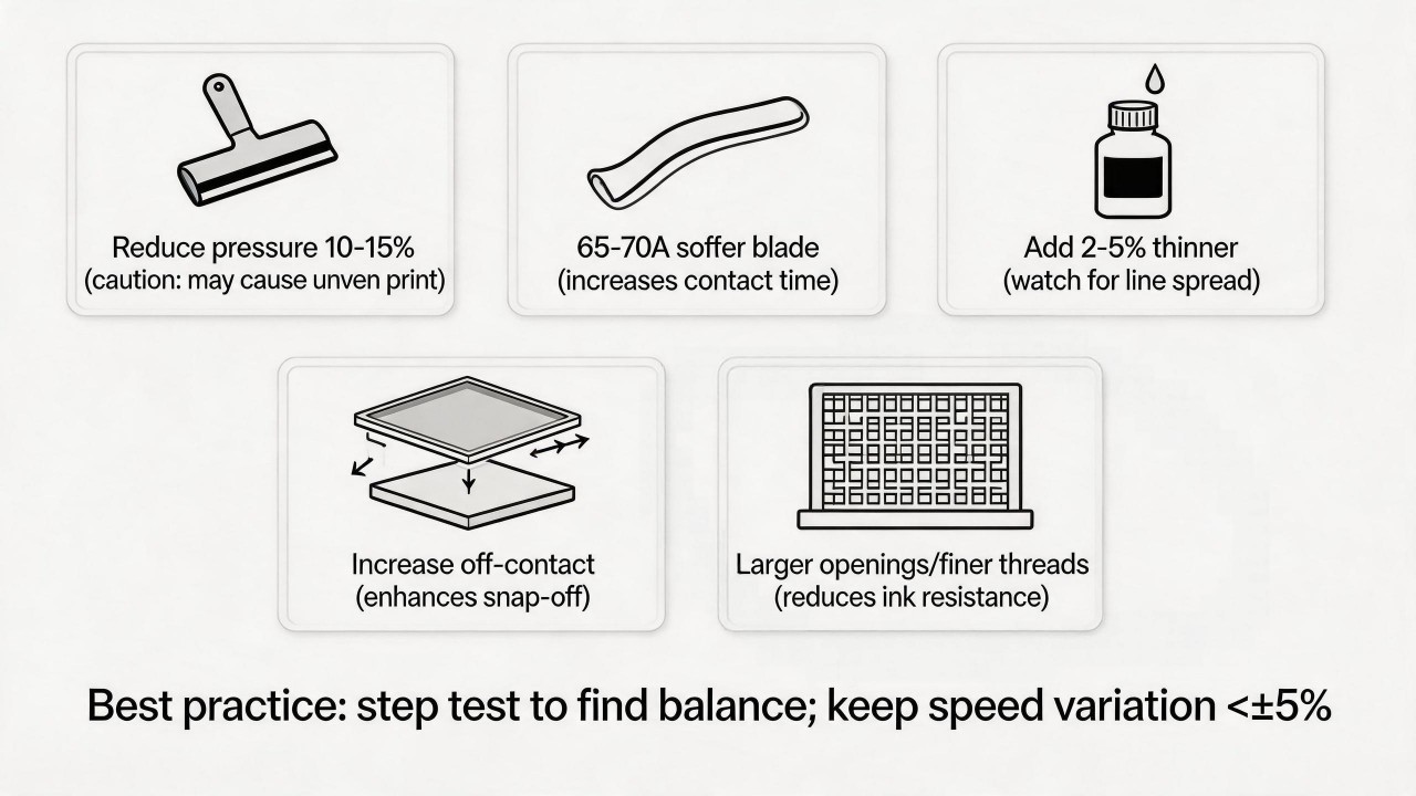 In actual production, the most commonly used compensation approach is to simultaneously adjust squeegee pressure and ink viscosity. First try reducing squeegee pressure by 10%-15% while adding 2%-5% thinner to reduce ink viscosity, then observe the change in ink film through test prints. If the ink film remains too thin, consider switching to a softer squeegee or adjusting the off-contact distance.
It is particularly important to note that any compensation measure will affect other print quality metrics; for instance, reducing viscosity may cause lines to widen, and reducing pressure may lead to uneven print coverage. Therefore, it is advisable to find the optimal balance through step testing. For high-precision printing, maintaining a stable printing speed is always the best strategy, and speed variation should be kept within ±5% to avoid the frequent use of compensation measures.
In actual production, the most commonly used compensation approach is to simultaneously adjust squeegee pressure and ink viscosity. First try reducing squeegee pressure by 10%-15% while adding 2%-5% thinner to reduce ink viscosity, then observe the change in ink film through test prints. If the ink film remains too thin, consider switching to a softer squeegee or adjusting the off-contact distance.
It is particularly important to note that any compensation measure will affect other print quality metrics; for instance, reducing viscosity may cause lines to widen, and reducing pressure may lead to uneven print coverage. Therefore, it is advisable to find the optimal balance through step testing. For high-precision printing, maintaining a stable printing speed is always the best strategy, and speed variation should be kept within ±5% to avoid the frequent use of compensation measures.Why does one side of the same glass sheet end up with thicker ink while the other side is thinner, and where does the root cause lie?
When ink film is thicker on the left and thinner on the right across the same glass sheet, the root cause of this typical side-to-side non-uniformity usually lies in issues with equipment leveling, squeegee condition, or the consistency of screen tension. It is not a problem of ink or a single parameter, but rather a deviation at the mechanical or tooling level. The most likely first root cause is unequal squeegee pressure between left and right. If the squeegee pressure adjustment mechanism of the printing press is set differently on the left and right sides, or if the equipment itself is off-level, it will result in greater pressure on the left and lighter pressure on the right. On the side with higher pressure, the screen contacts the glass more tightly, forcing more ink through the mesh openings and producing a thicker ink film; on the side with lower pressure, the contact is less tight, less ink is deposited, and the film is thinner. This situation is particularly common on manual and semi-automatic presses, and even fully automatic equipment can develop this issue due to mechanical wear from prolonged use.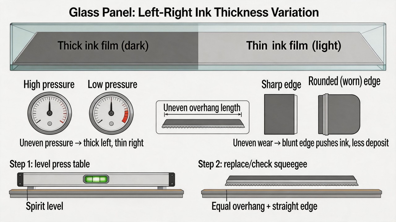 The second root cause is squeegee blade wear or improper installation. If the left edge of the squeegee remains sharp while the right edge has become rounded and blunt, the left side will deposit a normal amount of ink during printing, whereas the blunt right edge will tend to "push" the ink rather than "shear" it down, resulting in reduced ink deposit on the right side. Similarly, if the squeegee is installed with unequal overhang on the left and right ends, or if the squeegee itself is bent or deformed, this will also create differences in the effective print angle and pressure along the left–right direction, leading to uneven ink film thickness.
The third root cause is non-uniform screen tension distribution. On a properly manufactured screen, the tension should be uniform across the entire surface. If the screen was improperly stretched during fabrication, resulting in high tension on the left and low tension on the right, then during printing the high-tension area will snap off quickly and peel cleanly from the glass, leaving a relatively thin and uniform ink film; the low-tension area will snap off slowly and peel sluggishly, and may actually end up with a thicker film because the screen remains in contact with the glass for a longer time. This situation frequently occurs with low-quality screens or screens that have been used for too long and have developed localized relaxation.
The fourth root cause is inconsistent off-contact distance (the gap between the screen and the glass) from left to right. If the screen frame or the printing table is not leveled, resulting in a larger gap on the left and a smaller gap on the right, then the side with the larger gap will require greater squeegee pressure to bring the screen into contact with the glass; if the pressure is not correspondingly adjusted, insufficient ink deposition and a thinner film will result, whereas the side with the smaller gap makes contact easily and deposits a normal or greater amount of ink. This type of problem is usually accompanied by improper leveling of the equipment table or screen frame installation.
The second root cause is squeegee blade wear or improper installation. If the left edge of the squeegee remains sharp while the right edge has become rounded and blunt, the left side will deposit a normal amount of ink during printing, whereas the blunt right edge will tend to "push" the ink rather than "shear" it down, resulting in reduced ink deposit on the right side. Similarly, if the squeegee is installed with unequal overhang on the left and right ends, or if the squeegee itself is bent or deformed, this will also create differences in the effective print angle and pressure along the left–right direction, leading to uneven ink film thickness.
The third root cause is non-uniform screen tension distribution. On a properly manufactured screen, the tension should be uniform across the entire surface. If the screen was improperly stretched during fabrication, resulting in high tension on the left and low tension on the right, then during printing the high-tension area will snap off quickly and peel cleanly from the glass, leaving a relatively thin and uniform ink film; the low-tension area will snap off slowly and peel sluggishly, and may actually end up with a thicker film because the screen remains in contact with the glass for a longer time. This situation frequently occurs with low-quality screens or screens that have been used for too long and have developed localized relaxation.
The fourth root cause is inconsistent off-contact distance (the gap between the screen and the glass) from left to right. If the screen frame or the printing table is not leveled, resulting in a larger gap on the left and a smaller gap on the right, then the side with the larger gap will require greater squeegee pressure to bring the screen into contact with the glass; if the pressure is not correspondingly adjusted, insufficient ink deposition and a thinner film will result, whereas the side with the smaller gap makes contact easily and deposits a normal or greater amount of ink. This type of problem is usually accompanied by improper leveling of the equipment table or screen frame installation.
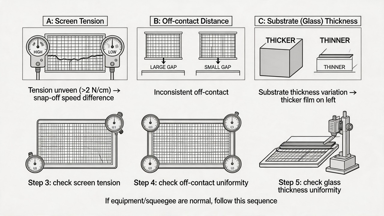 A fifth possible but less common cause is uneven thickness of the glass itself. If the glass substrate has a significant thickness difference between the left and right sides—for instance, the left side is thicker than the right—then, under a fixed off-contact distance and squeegee pressure, the thicker side will press the screen into tighter contact with the glass, depositing more ink and resulting in a thicker ink film. This may occur with lower-quality float glass or glass with poor cutting precision.
To resolve this problem, it is recommended to follow the sequence below for diagnosis: Step 1: Check the levelness of the printing table, calibrate with a spirit level, and ensure the table is evenly leveled from left to right. Step 2: Inspect the squeegee condition; replace with a new squeegee and ensure equal overhang on both sides and a straight blade edge during installation. Step 3: Use a tension meter to measure the tension values at the left, center, and right points of the screen, and confirm they are within the permissible deviation range (typically no more than 2 N/cm difference across the whole screen). Step 4: Check whether the off-contact distance is consistent from left to right, using a feeler gauge or off-contact gauge to measure the distance between the four corners of the screen and the glass. Step 5: If all the above are normal, then inspect the thickness uniformity of the glass substrate itself. In most cases, the first two steps will resolve the issue of left–right ink film unevenness.
A fifth possible but less common cause is uneven thickness of the glass itself. If the glass substrate has a significant thickness difference between the left and right sides—for instance, the left side is thicker than the right—then, under a fixed off-contact distance and squeegee pressure, the thicker side will press the screen into tighter contact with the glass, depositing more ink and resulting in a thicker ink film. This may occur with lower-quality float glass or glass with poor cutting precision.
To resolve this problem, it is recommended to follow the sequence below for diagnosis: Step 1: Check the levelness of the printing table, calibrate with a spirit level, and ensure the table is evenly leveled from left to right. Step 2: Inspect the squeegee condition; replace with a new squeegee and ensure equal overhang on both sides and a straight blade edge during installation. Step 3: Use a tension meter to measure the tension values at the left, center, and right points of the screen, and confirm they are within the permissible deviation range (typically no more than 2 N/cm difference across the whole screen). Step 4: Check whether the off-contact distance is consistent from left to right, using a feeler gauge or off-contact gauge to measure the distance between the four corners of the screen and the glass. Step 5: If all the above are normal, then inspect the thickness uniformity of the glass substrate itself. In most cases, the first two steps will resolve the issue of left–right ink film unevenness.What are the three most likely problems to occur when temperature and humidity in the printing workshop are out of control?
When temperature and humidity in the printing workshop are out of control, the three most likely problems are: screen clogging (scumming), dust attraction caused by static electricity, and misregistration or uneven ink film thickness. These three occur with the highest frequency and have the most direct impact on print quality.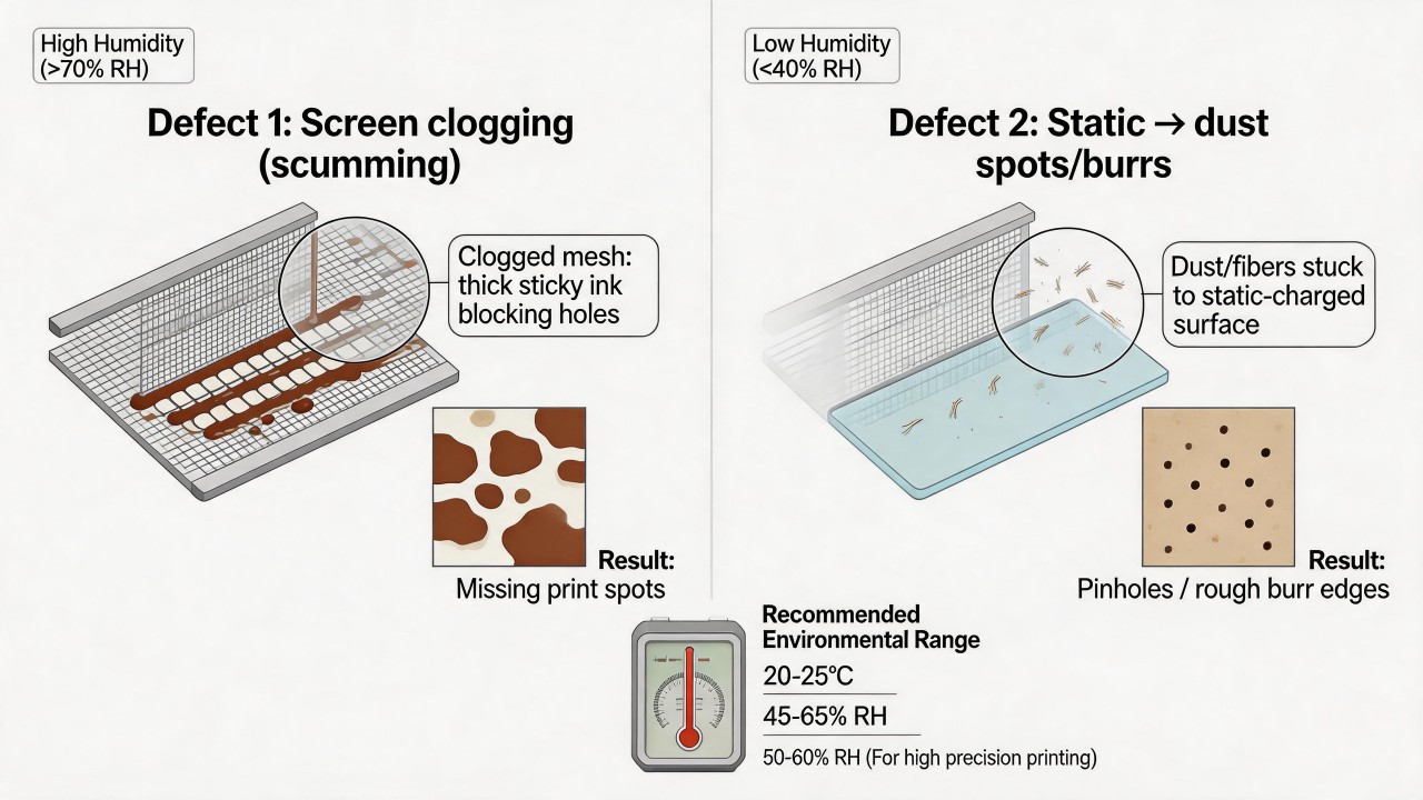 The first problem is screen clogging or scumming. When humidity is excessively high (e.g., above 70%), moisture in the air hinders the evaporation of solvents or water in the ink, causing the ink to become viscous or even form a skin within the mesh openings, leading to blocked mesh and resulting in localized missing prints or incomplete patterns during printing. Conversely, when temperature is too high and humidity too low (e.g., temperature above 30°C and humidity below 40%), the solvents in the ink evaporate too quickly, drying the ink on the screen rapidly and likewise clogging the mesh openings; this is particularly pronounced in fine line and halftone dot areas. Such a defect worsens progressively during continuous printing, necessitating frequent stops to wipe the screen after every few prints, severely impacting production efficiency.
The second problem is dust attraction and burring caused by static electricity. When workshop humidity is too low (below 40%), especially during dry winter months, static electricity tends to accumulate on the surfaces of the screen, squeegee, and substrate (particularly insulating materials like glass and plastic). The static charge attracts tiny airborne dust particles and fibers, which adhere to the underside of the screen or the substrate surface and, after printing, form pinholes, white spots, or burr-like defects in the pattern. For high-precision logos and transparent glass printing, such dust defects are especially glaring when inspected under backlight or strong light, causing a significant rise in the rejection rate. Static electricity can also cause irregular cobwebbing or ink mist from the screen, further contaminating the printed surface.
The third problem is misregistration or uneven ink film thickness. Uncontrolled temperature and humidity can cause dimensional changes in the screen, substrate, and printing equipment. Polyester screens are highly sensitive to humidity: when humidity rises, the mesh absorbs moisture and expands, leading to a drop in screen tension and an increase in pattern dimensions; when humidity falls, the mesh contracts, tension rises, and pattern dimensions shrink. Such dimensional changes directly cause misalignment between different colors in multi-color printing; even if the registration tolerance was originally kept within ±0.1 mm, it can widen to ±0.3 mm or more. Meanwhile, although the glass substrate itself is not very sensitive to temperature and humidity, if the temperature difference between the glass surface and the workshop is too great, condensation mist can form, compromising ink adhesion and film uniformity. Furthermore, ink viscosity changes noticeably with temperature—when temperature rises, the ink becomes thinner and the film gets lighter; when temperature drops, the ink thickens, the film becomes heavier and is prone to cobwebbing, further aggravating unevenness in the left–right or front–back direction.The third problem is misregistration or uneven ink film thickness. Uncontrolled temperature and humidity can cause dimensional changes in the screen, substrate, and printing equipment. Polyester screens are highly sensitive to humidity: when humidity rises, the mesh absorbs moisture and expands, leading to a drop in screen tension and an increase in pattern dimensions; when humidity falls, the mesh contracts, tension rises, and pattern dimensions shrink. Such dimensional changes directly cause misalignment between different colors in multi-color printing; even if the registration tolerance was originally kept within ±0.1 mm, it can widen to ±0.3 mm or more. Meanwhile, although the glass substrate itself is not very sensitive to temperature and humidity, if the temperature difference between the glass surface and the workshop is too great, condensation mist can form, compromising ink adhesion and film uniformity. Furthermore, ink viscosity changes noticeably with temperature—when temperature rises, the ink becomes thinner and the film gets lighter; when temperature drops, the ink thickens, the film becomes heavier and is prone to cobwebbing, further aggravating unevenness in the left–right or front–back direction.
The first problem is screen clogging or scumming. When humidity is excessively high (e.g., above 70%), moisture in the air hinders the evaporation of solvents or water in the ink, causing the ink to become viscous or even form a skin within the mesh openings, leading to blocked mesh and resulting in localized missing prints or incomplete patterns during printing. Conversely, when temperature is too high and humidity too low (e.g., temperature above 30°C and humidity below 40%), the solvents in the ink evaporate too quickly, drying the ink on the screen rapidly and likewise clogging the mesh openings; this is particularly pronounced in fine line and halftone dot areas. Such a defect worsens progressively during continuous printing, necessitating frequent stops to wipe the screen after every few prints, severely impacting production efficiency.
The second problem is dust attraction and burring caused by static electricity. When workshop humidity is too low (below 40%), especially during dry winter months, static electricity tends to accumulate on the surfaces of the screen, squeegee, and substrate (particularly insulating materials like glass and plastic). The static charge attracts tiny airborne dust particles and fibers, which adhere to the underside of the screen or the substrate surface and, after printing, form pinholes, white spots, or burr-like defects in the pattern. For high-precision logos and transparent glass printing, such dust defects are especially glaring when inspected under backlight or strong light, causing a significant rise in the rejection rate. Static electricity can also cause irregular cobwebbing or ink mist from the screen, further contaminating the printed surface.
The third problem is misregistration or uneven ink film thickness. Uncontrolled temperature and humidity can cause dimensional changes in the screen, substrate, and printing equipment. Polyester screens are highly sensitive to humidity: when humidity rises, the mesh absorbs moisture and expands, leading to a drop in screen tension and an increase in pattern dimensions; when humidity falls, the mesh contracts, tension rises, and pattern dimensions shrink. Such dimensional changes directly cause misalignment between different colors in multi-color printing; even if the registration tolerance was originally kept within ±0.1 mm, it can widen to ±0.3 mm or more. Meanwhile, although the glass substrate itself is not very sensitive to temperature and humidity, if the temperature difference between the glass surface and the workshop is too great, condensation mist can form, compromising ink adhesion and film uniformity. Furthermore, ink viscosity changes noticeably with temperature—when temperature rises, the ink becomes thinner and the film gets lighter; when temperature drops, the ink thickens, the film becomes heavier and is prone to cobwebbing, further aggravating unevenness in the left–right or front–back direction.The third problem is misregistration or uneven ink film thickness. Uncontrolled temperature and humidity can cause dimensional changes in the screen, substrate, and printing equipment. Polyester screens are highly sensitive to humidity: when humidity rises, the mesh absorbs moisture and expands, leading to a drop in screen tension and an increase in pattern dimensions; when humidity falls, the mesh contracts, tension rises, and pattern dimensions shrink. Such dimensional changes directly cause misalignment between different colors in multi-color printing; even if the registration tolerance was originally kept within ±0.1 mm, it can widen to ±0.3 mm or more. Meanwhile, although the glass substrate itself is not very sensitive to temperature and humidity, if the temperature difference between the glass surface and the workshop is too great, condensation mist can form, compromising ink adhesion and film uniformity. Furthermore, ink viscosity changes noticeably with temperature—when temperature rises, the ink becomes thinner and the film gets lighter; when temperature drops, the ink thickens, the film becomes heavier and is prone to cobwebbing, further aggravating unevenness in the left–right or front–back direction.
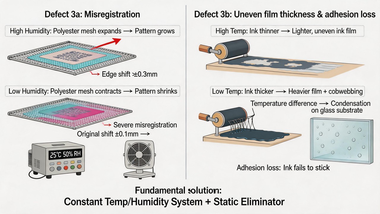 Therefore, controlling temperature and humidity in the printing workshop is the fundamental condition for ensuring stable print quality. The generally recommended range is: temperature 20–25°C, relative humidity 45–65%. For high-precision glass printing, it is advisable to strictly control humidity between 50–60% and temperature between 22–24°C, while equipping the workshop with a constant temperature and humidity system and installing static eliminators to reduce the risk of dust attraction caused by static electricity.
Can double printing solve the pinhole problem, and what new risks will it introduce?
Double printing (i.e., printing again on glass that has already been printed and dried/sintered once) can indeed be used to address the pinhole issue, especially for fine pinholes caused by dust, bubbles, or minor ink unevenness, as the second ink film can physically cover them. However, this method is not a universal remedy and will introduce a series of new risks, requiring careful evaluation. The prerequisite for double printing to solve the pinhole problem is that the pinholes are relatively small in size (typically less than 0.3 mm in diameter) and that the pinholes do not penetrate to the substrate or the first ink film has already formed a basic coverage. During the second print, fresh ink fills into the recesses of the pinholes, and the surface becomes smooth after drying. The effect of double printing is particularly pronounced for bubble-type pinholes caused by incomplete deaeration of the ink. However, if the pinholes are caused by severe contamination of the substrate surface (such as oil stains) or by cratering of the ink itself, double printing often fails to cover them, because the second ink layer will likewise suffer from cratering or poor adhesion at the same locations.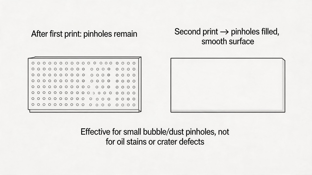 Nevertheless, double printing introduces a series of new risks, the foremost being registration accuracy. During the second print, the screen pattern must precisely align with the pattern from the first print; even a deviation of ±0.1 mm will produce noticeable ghosting or double-edging along the edges of fine logos or lines, appearing as a "ghost image" that is even more unsightly than the original pinholes. For high-precision products, such registration deviation is often unacceptable. Even if the pattern dimensions were intentionally enlarged during the first print to provide allowance for the second print, this increases design difficulty and screen-making costs.
The second significant risk is adhesion and durability problems caused by an excessively thick ink film. The superimposition of two prints can double the total ink film thickness (e.g., from 15 μm to over 30 μm). An overly thick ink film is prone to internal stress during sintering or curing, leading to cracking, lifting, or reduced adhesion. Especially for ceramic inks requiring high-temperature sintering, two sintering cycles may cause the first layer to over-melt while the second layer remains under-sintered, actually worsening the interfacial bond strength. In subsequent use, the excessively thick ink film is more likely to be peeled off in whole pieces by alcohol wiping or mechanical friction rather than wearing away locally.
The third risk is inconsistency in color and appearance. If the inks used for the two prints are from different batches, cured under different conditions, or if a period of time has elapsed after the first print, color differences may appear after the second print, forming visible "joint marks" or "water marks" in solid background areas. Furthermore, the ink film thickness of the second print can never be perfectly identical to that of the first, resulting in localized raised areas in the printed region and creating a tactile step on the glass surface that compromises the hand feel and premium perception of the product.
Nevertheless, double printing introduces a series of new risks, the foremost being registration accuracy. During the second print, the screen pattern must precisely align with the pattern from the first print; even a deviation of ±0.1 mm will produce noticeable ghosting or double-edging along the edges of fine logos or lines, appearing as a "ghost image" that is even more unsightly than the original pinholes. For high-precision products, such registration deviation is often unacceptable. Even if the pattern dimensions were intentionally enlarged during the first print to provide allowance for the second print, this increases design difficulty and screen-making costs.
The second significant risk is adhesion and durability problems caused by an excessively thick ink film. The superimposition of two prints can double the total ink film thickness (e.g., from 15 μm to over 30 μm). An overly thick ink film is prone to internal stress during sintering or curing, leading to cracking, lifting, or reduced adhesion. Especially for ceramic inks requiring high-temperature sintering, two sintering cycles may cause the first layer to over-melt while the second layer remains under-sintered, actually worsening the interfacial bond strength. In subsequent use, the excessively thick ink film is more likely to be peeled off in whole pieces by alcohol wiping or mechanical friction rather than wearing away locally.
The third risk is inconsistency in color and appearance. If the inks used for the two prints are from different batches, cured under different conditions, or if a period of time has elapsed after the first print, color differences may appear after the second print, forming visible "joint marks" or "water marks" in solid background areas. Furthermore, the ink film thickness of the second print can never be perfectly identical to that of the first, resulting in localized raised areas in the printed region and creating a tactile step on the glass surface that compromises the hand feel and premium perception of the product.
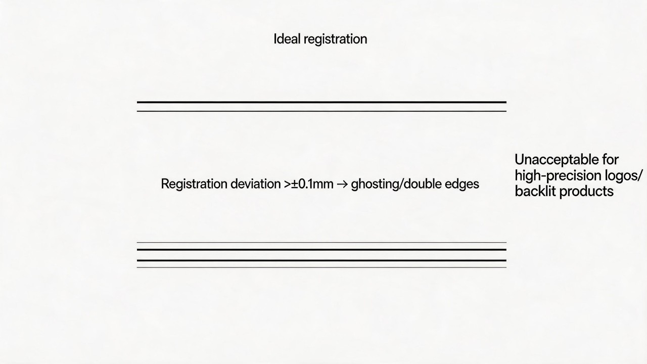 The fourth risk is a substantial increase in production efficiency and cost. Double printing entails running the glass through the machine twice and drying or sintering twice, doubling the production time and correspondingly increasing energy and labor costs. If pinholes are still present after the second print, or if new registration deviations occur, the entire glass sheet will need to be scrapped or subjected to a third print, causing the rejection rate and cost to surge sharply. For mass production, this is often counterproductive.
Therefore, double printing should be regarded as a temporary remedial measure rather than a routine production process. A more fundamental solution is to identify the root cause of pinhole formation: check whether the ink has been sufficiently deaerated, whether the screen is clean, whether the workshop environment is dust-free, whether the glass surface has been properly cleaned, and whether the squeegee pressure is appropriate, among other factors. If pinhole problems occur frequently, it is advisable to first optimize the single-print process and control the pinhole rate within an acceptable range (e.g., below 1%), rather than relying on double printing as a fallback. Only in cases where a small number of pinholes appear occasionally, the product value is high, and slight registration deviation is permissible, should double printing be considered as a repair method. For high-precision logos and transparent backlit products, double printing is strongly discouraged, as registration ghosting and the tactile step of the ink film will seriously compromise the final quality.
The fourth risk is a substantial increase in production efficiency and cost. Double printing entails running the glass through the machine twice and drying or sintering twice, doubling the production time and correspondingly increasing energy and labor costs. If pinholes are still present after the second print, or if new registration deviations occur, the entire glass sheet will need to be scrapped or subjected to a third print, causing the rejection rate and cost to surge sharply. For mass production, this is often counterproductive.
Therefore, double printing should be regarded as a temporary remedial measure rather than a routine production process. A more fundamental solution is to identify the root cause of pinhole formation: check whether the ink has been sufficiently deaerated, whether the screen is clean, whether the workshop environment is dust-free, whether the glass surface has been properly cleaned, and whether the squeegee pressure is appropriate, among other factors. If pinhole problems occur frequently, it is advisable to first optimize the single-print process and control the pinhole rate within an acceptable range (e.g., below 1%), rather than relying on double printing as a fallback. Only in cases where a small number of pinholes appear occasionally, the product value is high, and slight registration deviation is permissible, should double printing be considered as a repair method. For high-precision logos and transparent backlit products, double printing is strongly discouraged, as registration ghosting and the tactile step of the ink film will seriously compromise the final quality.
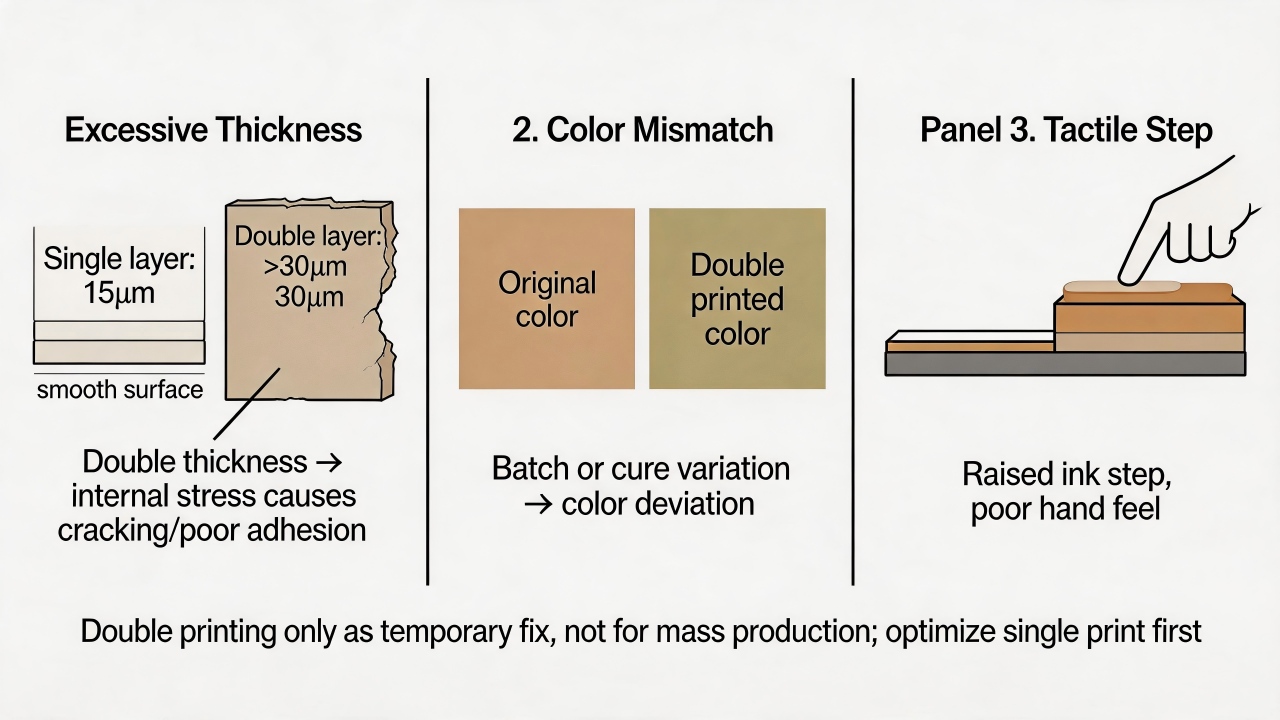
How will the "ghost image" left by incomplete screen cleaning affect the next batch of products?
The "ghost image" left by incomplete screen cleaning (i.e., the residual image of the previous pattern on the screen) will impact the print quality of the next batch of products in multiple ways, the most typical being the appearance of unwanted ghosting or halos along the edges of the new pattern. When residual emulsion or ink in the "ghost" area alters the local thickness and surface energy of the screen, during the next print run, after the squeegee stroke, ink will preferentially penetrate through areas where the residue is thinner or has better ink affinity, resulting in unexpected light-colored tails or double contours along the edges of the new pattern, appearing as a blurred shadow next to the intended design. For high-precision logos and fine lines, such ghosting makes line edges rough and unclean, severely undermining the clarity and refinement of the product. The second significant impact is a decline in the dimensional accuracy and registration stability of the new pattern. The mesh fabric in the "ghost" area becomes partially clogged or stiffened by residues, causing the elasticity and snap-off behavior of that area to differ from other regions. When the new printed pattern happens to span across the "ghost" region, the screen cannot uniformly contact and peel away during squeegee travel, resulting in abnormal local ink deposit and local stretching or contraction of the pattern. In multi-color printing, the different distribution of "ghost" residues on different color screens will cause registration accuracy to fall out of control; even if the equipment parameters remain unchanged, products from different batches may exhibit noticeable misalignment and dimensional deviation.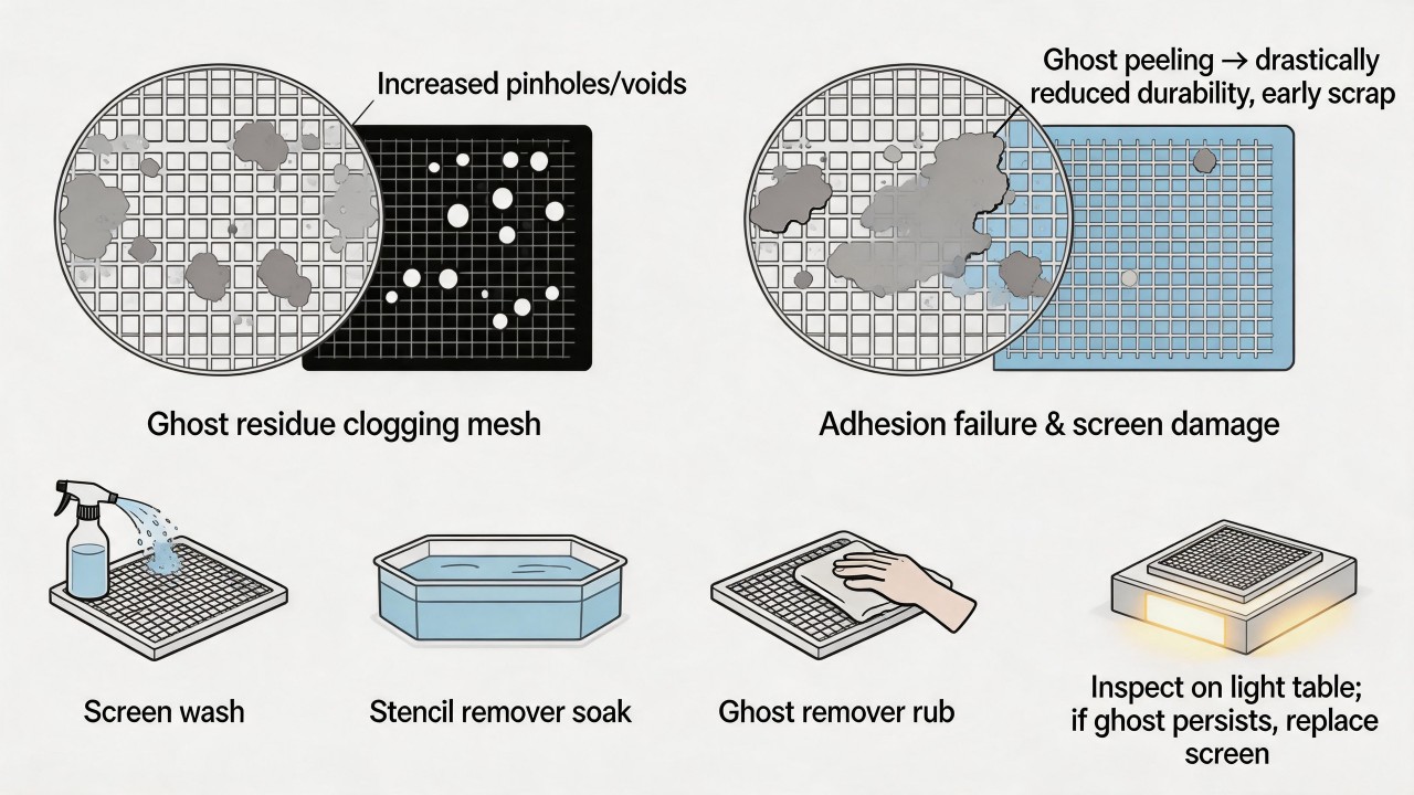 The third impact is an increase in pinholes and defect rates in the new products. The "ghost" area is often accompanied by minute residual particles or gel fragments, which can directly block mesh openings during the next print run, causing pinholes or localized missing prints in the new pattern. More problematically, these residues may be covered over when fresh emulsion is applied to a new screen, introducing hidden defects during the screen-making process that only become apparent after exposure and development, leading to screen scrappage. Even without complete mesh blockage, residues can alter the flow path of the ink, producing irregular ink spots or cobwebbing on the new pattern, which are particularly conspicuous under backlight inspection, especially in solid background and halftone dot areas.
The fourth impact is a significant reduction in the screen's print durability. The adhesion between the emulsion residues in the "ghost" area and the freshly coated emulsion layer is weak, making them prone to detach from the mesh fabric during the printing process. These detached gel fragments can move with the squeegee, further scratching or clogging other mesh openings, causing the screen to suffer large-area damage long before reaching its normal service life. In cases where polyester mesh is used, residues may also absorb moisture, leading to localized tension loss and accelerating the fatigue and scrappage of the entire screen.
Therefore, when cleaning screens, it is essential not only to remove surface ink but also to completely eliminate emulsion residues. A three-step cleaning process is recommended: first, use screen wash to remove ink; next, soak with a stencil remover solution to strip away the old emulsion; finally, apply ghost remover in a circular motion to remove stubborn residues from the image area. After cleaning, the screen should be inspected on a light table to ensure the entire mesh surface is transparent and clean, free of any shadow marks. For high-precision glass printing, it is advisable to perform thorough cleaning and reclamation immediately after completing each batch of products, and not to store screens for extended periods before reuse for the next batch, as residual "ghosts" become increasingly difficult to remove over time. If "ghost" images have already formed and cannot be completely eliminated, the safest course of action is to scrap the screen and re-stretch a new one for plate-making, rather than taking the risk of using it for the next batch of high-specification products.
The third impact is an increase in pinholes and defect rates in the new products. The "ghost" area is often accompanied by minute residual particles or gel fragments, which can directly block mesh openings during the next print run, causing pinholes or localized missing prints in the new pattern. More problematically, these residues may be covered over when fresh emulsion is applied to a new screen, introducing hidden defects during the screen-making process that only become apparent after exposure and development, leading to screen scrappage. Even without complete mesh blockage, residues can alter the flow path of the ink, producing irregular ink spots or cobwebbing on the new pattern, which are particularly conspicuous under backlight inspection, especially in solid background and halftone dot areas.
The fourth impact is a significant reduction in the screen's print durability. The adhesion between the emulsion residues in the "ghost" area and the freshly coated emulsion layer is weak, making them prone to detach from the mesh fabric during the printing process. These detached gel fragments can move with the squeegee, further scratching or clogging other mesh openings, causing the screen to suffer large-area damage long before reaching its normal service life. In cases where polyester mesh is used, residues may also absorb moisture, leading to localized tension loss and accelerating the fatigue and scrappage of the entire screen.
Therefore, when cleaning screens, it is essential not only to remove surface ink but also to completely eliminate emulsion residues. A three-step cleaning process is recommended: first, use screen wash to remove ink; next, soak with a stencil remover solution to strip away the old emulsion; finally, apply ghost remover in a circular motion to remove stubborn residues from the image area. After cleaning, the screen should be inspected on a light table to ensure the entire mesh surface is transparent and clean, free of any shadow marks. For high-precision glass printing, it is advisable to perform thorough cleaning and reclamation immediately after completing each batch of products, and not to store screens for extended periods before reuse for the next batch, as residual "ghosts" become increasingly difficult to remove over time. If "ghost" images have already formed and cannot be completely eliminated, the safest course of action is to scrap the screen and re-stretch a new one for plate-making, rather than taking the risk of using it for the next batch of high-specification products.
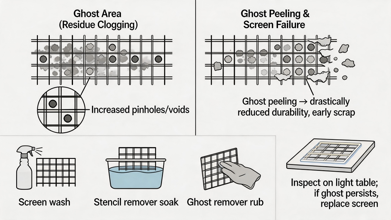
Sintering and Heat Treatment
How significant is the color difference when the sintering temperature deviates by 10°C from the optimal window?
A deviation of 10°C from the optimal sintering temperature window is sufficient to cause color changes visible to the naked eye, with the severity depending on the material system and color. For systems that are less sensitive to color change, the color difference value (ΔE) may still exceed 1.5, which already reaches the threshold of naked-eye discernibility; for color-sensitive systems, the ΔE value can be as high as 3 or more, making the difference very pronounced, and products from different batches will exhibit significant visual disparity in color.
Fluctuations in sintering temperature affect the final color development through two primary mechanisms. The first mechanism is altering the crystallization process of the pigment, thereby changing color appearance. Temperature deviation affects the chemical reaction and crystal structure formation of the pigment at high temperatures: excessive temperature may destroy the already-formed stable color structure, leading to lighter color; insufficient temperature may result in poor crystal development, causing the color to appear dull and less vivid, or even directly failing to meet color saturation standards. The second mechanism is changing the microstructure of the material itself, thereby affecting color tendency. For example, over-firing may cause the ink surface to lose gloss, or induce oxidation of certain components in the glass or ink, leading to color shifts such as yellowing or graying.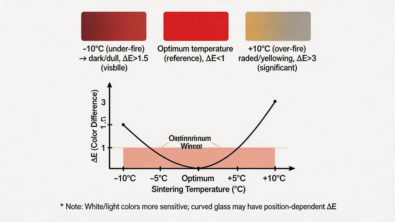 In actual production, different colors and different types of glass products exhibit varying sensitivity to temperature deviation. Due to the influence of impurities, white and light-colored materials tend to show more pronounced color differences; by contrast, some dark-colored materials possess relatively better heat resistance, and their color change may be somewhat smaller. At the same time, the shape of the glass product also affects the difficulty of temperature control. For instance, with 2.5D or 3D curved glass, temperature differences readily occur between the edges and the center during sintering, resulting in localized color variation. Even if the average furnace temperature is controlled within ±10°C, the color difference at different positions on the curved surface may still exceed the acceptable range.
To ensure color stability, two aspects must be controlled in production. First, the temperature field inside the furnace must be precisely monitored; it is recommended to use multiple thermocouples to measure temperature in real time at different positions, aiming to control sintering temperature fluctuation within ±5°C rather than relying on the single-point temperature display integrated with the furnace. Second, standard color samples should be established and a colorimeter used for quantitative management, employing the ΔE value as the basis for product release and process adjustment. When the ΔE value exceeds the standard, a timely investigation should be conducted into whether the sintering equipment has aged, whether the process parameters have drifted, or whether the ink batch has changed, so as to stabilize color quality through scientific data management rather than relying solely on visual judgment.
In actual production, different colors and different types of glass products exhibit varying sensitivity to temperature deviation. Due to the influence of impurities, white and light-colored materials tend to show more pronounced color differences; by contrast, some dark-colored materials possess relatively better heat resistance, and their color change may be somewhat smaller. At the same time, the shape of the glass product also affects the difficulty of temperature control. For instance, with 2.5D or 3D curved glass, temperature differences readily occur between the edges and the center during sintering, resulting in localized color variation. Even if the average furnace temperature is controlled within ±10°C, the color difference at different positions on the curved surface may still exceed the acceptable range.
To ensure color stability, two aspects must be controlled in production. First, the temperature field inside the furnace must be precisely monitored; it is recommended to use multiple thermocouples to measure temperature in real time at different positions, aiming to control sintering temperature fluctuation within ±5°C rather than relying on the single-point temperature display integrated with the furnace. Second, standard color samples should be established and a colorimeter used for quantitative management, employing the ΔE value as the basis for product release and process adjustment. When the ΔE value exceeds the standard, a timely investigation should be conducted into whether the sintering equipment has aged, whether the process parameters have drifted, or whether the ink batch has changed, so as to stabilize color quality through scientific data management rather than relying solely on visual judgment.How does the change in furnace loading capacity affect thermal inertia, and what are the differences in sintering effects between an empty furnace and a fully loaded furnace?
A change in furnace loading capacity essentially alters the total thermal capacity of the entire furnace chamber system: the greater the loading capacity, the larger the furnace's "thermal inertia." Thermal inertia can be understood as the furnace's "reluctance" to resist temperature changes, which is jointly determined by the furnace chamber structure and the materials inside it; the larger the total thermal capacity, the slower and more sluggish the temperature rise and fall become.
When the furnace is in an empty state, the total thermal capacity of the chamber is low and the thermal inertia is small, so the system responds rapidly to temperature changes and startup energy consumption is low. However, once the set temperature is reached, the lack of heat-absorbing materials means the system must continuously output relatively high power to maintain the temperature, easily leading to energy waste and temperature fluctuations. At the same time, thermal radiation and convective circulation within an empty furnace are "freer," making overall temperature uniformity relatively easy to control. When the furnace is in a fully loaded state, the total thermal capacity of the chamber is high and the thermal inertia is large; the large quantity of materials absorbs and stores heat, causing the entire heating and cooling process to be very slow. Nonetheless, once the material temperature stabilizes, the thermal field inside the furnace also tends to stabilize, which is beneficial for energy efficiency optimization and temperature uniformity in mass production.Why must glass be printed with ceramic ink before tempering, and can it be remedied after tempering?
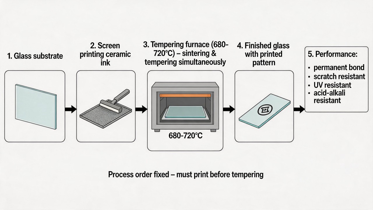
In glass screen printing, "printing must be done before tempering" is an iron law, and there is no conventional solution that can perfectly remedy the situation after tempering. The core reason behind this is that ceramic ink must rely on the high-temperature process of tempering to achieve a permanent bond with the glass. When the glass is heated in a tempering furnace to approximately 680°C to 720°C, this process simultaneously accomplishes physical strengthening and ink sintering. Ceramic ink (i.e., high-temperature inorganic ink) undergoes sintering at high temperatures; its inorganic powder reacts physico-chemically with the glass surface and fuses into one. This atomic-level bond gives the pattern extremely high adhesion and weatherability, making it resistant to scratching, UV radiation, acids, and alkalis, and it becomes an inseparable part of the glass.
So, why is it impossible to print on a piece of glass that has already been tempered? There are three potential approaches, but each has fatal flaws. The first is to sinter again at high temperature, which is completely unfeasible, because tempered glass has uniform stress distributed inside, which is the source of its strength. If it is heated again above 600°C, this stress distribution will be completely destroyed, causing the glass to deform, lose strength drastically, or even explode. Therefore, secondary high-temperature sintering is absolutely forbidden. The second is to use low-temperature ink. Although there are "bake-free" or "low-temperature" glass inks on the market that can cure at low temperatures (usually 100–200°C), their adhesion relies mainly on physical bonding, which is fundamentally different from the chemical bond of high-temperature sintering. Such ink is merely "stuck" to the surface rather than "grown" onto it; its adhesion, hardness, and weatherability are far inferior to those of high-temperature sintered ceramic ink, making it unable to meet the demands of long-term outdoor or high-requirement use, nor can it withstand extreme environments. The third is localized repair. For very small defects on finished products, using a repair pen or low-temperature ink for manual touch-up can only cover the defect; the durability of such a repair layer is very limited, and it wears off easily, failing to restore the original performance of the print.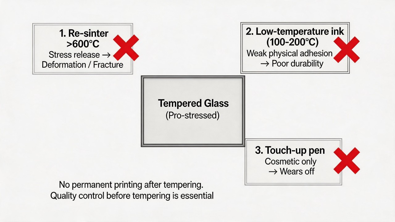 Therefore, the sequence of this process chain is fixed; if a printing defect is discovered after tempering, conventional processes can no longer remedy it. To ensure the final result, the best strategy is to strictly follow the process flow of "printing first, then tempering," and implement rigorous quality control at every stage. As a remedial measure, low-temperature ink cannot restore the original long-term durability and is generally not accepted. To avoid such irreversible losses from the source, it is necessary to strictly control printing quality before tempering and establish defect inspection standards after tempering.
Why does the color of screen-printed ceramic ink change on some glass after tempering?
Color change after tempering is an inherent characteristic of ceramic ink, but if the change exceeds expectations, it indicates that deviations may have occurred in the production process. The core reason is that the color of ceramic ink is "burned" into existence by the high temperature of the tempering furnace, and its final color development is extremely sensitive to factors such as temperature, time, and the glass substrate. Glass tempering itself is a thermal processing procedure, with temperatures typically ranging from 680°C to 720°C. Before tempering, the high-temperature ink is merely a coating on the glass surface, and its true "color development" and "fixation" are completed inside the tempering furnace. The pigments are composed of metal oxides such as copper, chromium, cobalt, and iron, and the tempering temperature happens to fall right within the range where these components undergo chemical reactions. With even a slight temperature deviation, the crystal structure and valence state of the pigments change, so the color will inevitably transform from the "printed color" to the "sintered color," and this change is universally present. It is precisely for this reason that color matching requires a high degree of skill, and manufacturers must predict the final color based on experience.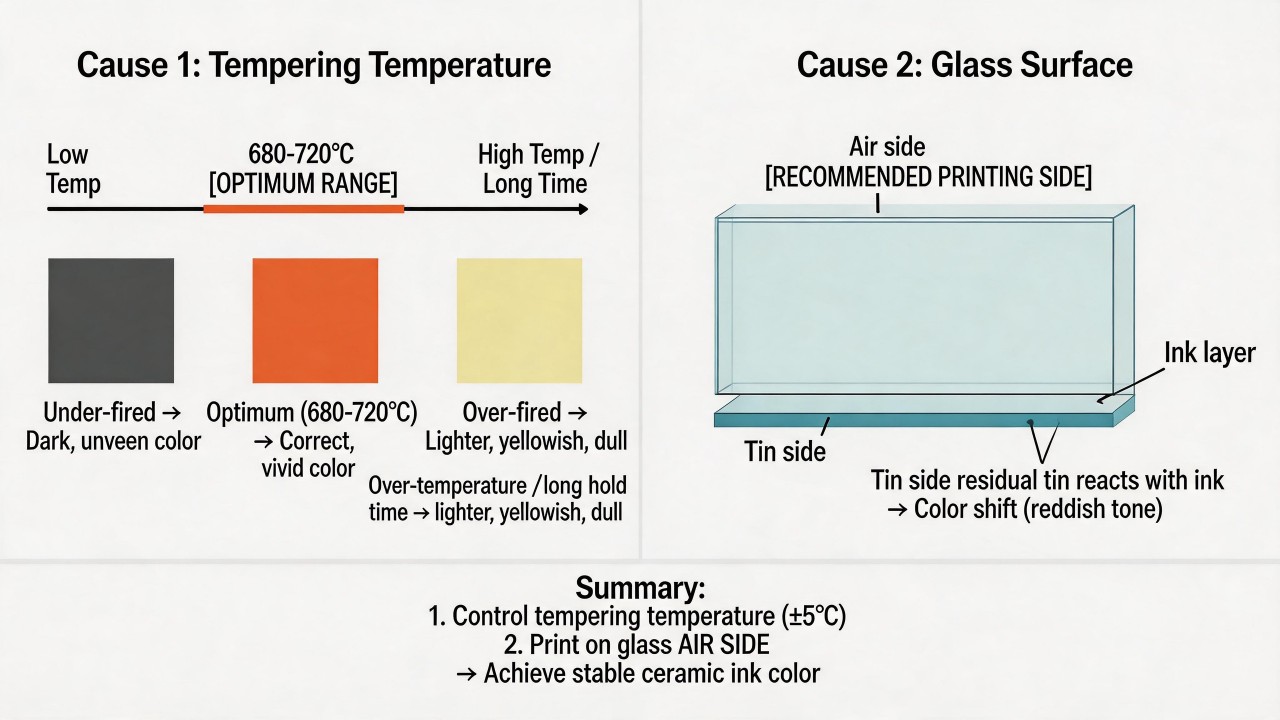 If the color change exceeds the normal range, it is generally caused by four categories of factors. The first is improper control of the tempering process, which is also the most common cause. Excessive temperature or overly long duration leads to "over-firing," making the color lighter, duller, or yellowish; uneven temperature distribution inside the furnace causes localized color differences within the same batch of glass. The second category is quality issues with the ink itself. Inks from different manufacturers have different formulations, resulting in different color development effects and temperature windows. Using inferior or improperly stored ink results in even poorer color stability during tempering and may even lead to severe discoloration. The third category is the influence of the glass substrate. Glass has an "air side" and a "tin side"; if the ink is printed on the "tin side," residual tin can chemically react with the ink, causing the color to turn reddish or produce a color shift. The fourth category involves human factors and batch variations, including improper dilution ratios when mixing the ink, uneven ink film thickness before tempering, and subtle differences between different production batches of ink—all of which can ultimately lead to color differences after sintering.
To avoid color variation problems after tempering, the key lies in strict process control. First, select reliable ink: use a proven, quality-stable brand of ink, and obtain its recommended sintering temperature and process window. Second, standardize process operations: strictly control the furnace temperature and time during tempering to remain within the window recommended by the ink supplier, and regularly check furnace temperature uniformity. At the same time, ensure correct printing: always print on the "air side" of the glass, and maintain stability in both the ink mixing ratio and the printed ink film thickness. Finally, strengthen quality control: use tools such as a colorimeter to compare post-tempering products from different batches against a standard color panel, and establish quantified quality control standards.
If the color change exceeds the normal range, it is generally caused by four categories of factors. The first is improper control of the tempering process, which is also the most common cause. Excessive temperature or overly long duration leads to "over-firing," making the color lighter, duller, or yellowish; uneven temperature distribution inside the furnace causes localized color differences within the same batch of glass. The second category is quality issues with the ink itself. Inks from different manufacturers have different formulations, resulting in different color development effects and temperature windows. Using inferior or improperly stored ink results in even poorer color stability during tempering and may even lead to severe discoloration. The third category is the influence of the glass substrate. Glass has an "air side" and a "tin side"; if the ink is printed on the "tin side," residual tin can chemically react with the ink, causing the color to turn reddish or produce a color shift. The fourth category involves human factors and batch variations, including improper dilution ratios when mixing the ink, uneven ink film thickness before tempering, and subtle differences between different production batches of ink—all of which can ultimately lead to color differences after sintering.
To avoid color variation problems after tempering, the key lies in strict process control. First, select reliable ink: use a proven, quality-stable brand of ink, and obtain its recommended sintering temperature and process window. Second, standardize process operations: strictly control the furnace temperature and time during tempering to remain within the window recommended by the ink supplier, and regularly check furnace temperature uniformity. At the same time, ensure correct printing: always print on the "air side" of the glass, and maintain stability in both the ink mixing ratio and the printed ink film thickness. Finally, strengthen quality control: use tools such as a colorimeter to compare post-tempering products from different batches against a standard color panel, and establish quantified quality control standards.
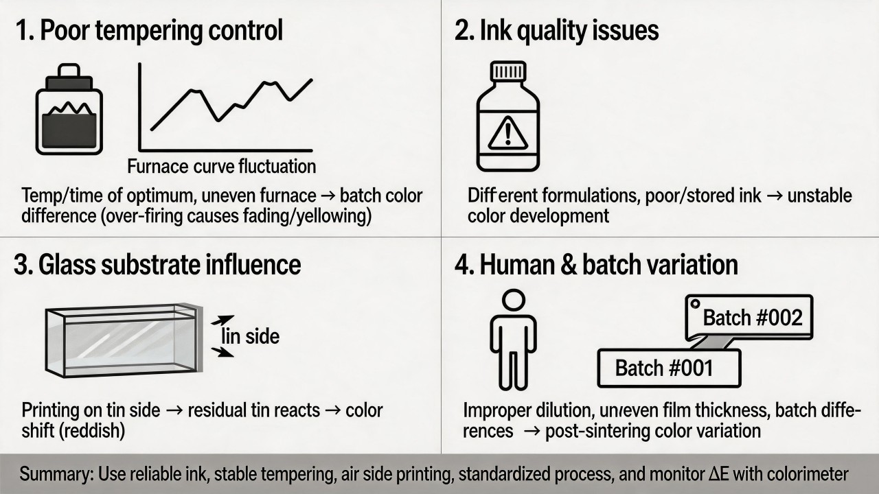
How do rapid sintering and prolonged holding affect adhesion differently?
In the glass tempering process, ink adhesion derives from the formation and wetting of the glass phase during sintering, a process that is directly related to both temperature and holding time. The reason why temperature profiles (i.e., rapid pass-through versus prolonged holding) produce radically different adhesion is fundamentally their control over the melting, flow, and interfacial chemical reactions of the glass frit in the ink. Rapid sintering (a non-standard tempering process): typically refers to reaching the target temperature in a very short time. If the heating rate is too fast and holding time insufficient within the tempering furnace, the ink layer may not fully melt and wet the substrate, liquid-phase sintering reactions are inadequate, and interfacial bond strength is weak, resulting in reduced adhesion and even possible micro-cracks due to internal stresses that had no time to relax. Prolonged holding (commonly used in glass tempering): In the tempering of automotive or appliance glass, the ink undergoes a "simultaneous sintering and tempering treatment." Sufficient holding time (e.g., 7 minutes for automotive rear-window silver paste to achieve good adhesion, or studies showing 4 minutes as the optimal window) allows the glass phase to soften fully, flow, and wet both the substrate and pigment particles, forming a dense, well-adhered enamel layer. However, excessively long holding may lead to devitrification of the ink or a reduction in the strength of the substrate.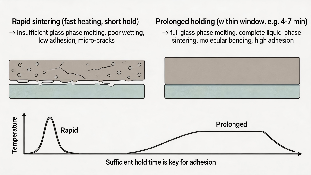 Taken together, the most fundamental difference lies in the adhesion mechanism: rapid sintering often results in insufficient physico-chemical fusion because the glass phase fails to melt fully and the organic components are not completely burned out; prolonged holding (within the process window) provides the necessary time for liquid-phase sintering, enabling molecular-level bonding between the ink and the glass surface, thus achieving high-strength adhesion. Furthermore, rapid sintering may introduce internal stresses due to severe thermal shock—a risk absent with prolonged holding combined with appropriate cooling.
Is glass deformation (warpage) after sintering related to the printed pattern?
The printed pattern has a direct and close relationship with the warpage deformation of glass after tempering. The core principle behind this is "stress imbalance": during the glass tempering process, the areas with printed ink and those without behave differently in terms of heat absorption and cooling, resulting in unbalanced internal stresses that in turn lead to deformation. Why does the printed pattern cause glass warpage? There are three main contributing factors. The first is the mismatch in thermal expansion coefficients, which is the most fundamental cause. The thermal expansion coefficients of glass and ceramic ink differ significantly; they expand to different extents when heated and contract to different extents when cooled. This “lack of synchronization” generates enormous stress within the glass. If the pattern design is not reasonable, these stresses cannot be balanced and ultimately manifest as warpage.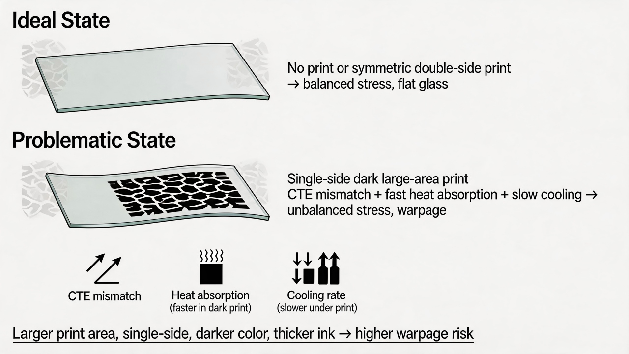 The second is uneven heat absorption. Dark-colored inks, especially black, absorb heat much faster than transparent glass. This causes the printed areas to heat up more rapidly inside the tempering furnace, creating a significant temperature difference with the unprinted glass areas, which in turn induces thermal deformation.
The third is inconsistent cooling rates. When the glass is rapidly cooled in the forced-air cooling section of the tempering furnace, the thick printed ink layer obstructs heat dissipation from the glass beneath it, making the cooling rate of the printed areas slower than that of the non-printed areas. The stress differential arising from the different cooling rates is another key reason for warpage.
What characteristics of the printed pattern exacerbate warpage? The first is the printing area: the larger the area, the higher the risk of warpage. The patterned region exerts a “pulling force” on the glass, and warpage is particularly pronounced with full-area single-sided printing. The second is the printing position: single-sided printing carries high risk, whereas double-sided printing or symmetrical design can effectively balance stress, forming a “sandwich” structure. If the stresses on both sides are balanced, the glass can remain flat. The third is the ink color: dark-colored inks (especially black) pose a far greater risk than light-colored ones, because dark inks absorb thermal radiation more strongly, leading to uneven heat absorption. The fourth is the ink film thickness: the thicker the ink, the stronger its ability to obstruct heat dissipation, and the greater the resulting stress and risk.
The second is uneven heat absorption. Dark-colored inks, especially black, absorb heat much faster than transparent glass. This causes the printed areas to heat up more rapidly inside the tempering furnace, creating a significant temperature difference with the unprinted glass areas, which in turn induces thermal deformation.
The third is inconsistent cooling rates. When the glass is rapidly cooled in the forced-air cooling section of the tempering furnace, the thick printed ink layer obstructs heat dissipation from the glass beneath it, making the cooling rate of the printed areas slower than that of the non-printed areas. The stress differential arising from the different cooling rates is another key reason for warpage.
What characteristics of the printed pattern exacerbate warpage? The first is the printing area: the larger the area, the higher the risk of warpage. The patterned region exerts a “pulling force” on the glass, and warpage is particularly pronounced with full-area single-sided printing. The second is the printing position: single-sided printing carries high risk, whereas double-sided printing or symmetrical design can effectively balance stress, forming a “sandwich” structure. If the stresses on both sides are balanced, the glass can remain flat. The third is the ink color: dark-colored inks (especially black) pose a far greater risk than light-colored ones, because dark inks absorb thermal radiation more strongly, leading to uneven heat absorption. The fourth is the ink film thickness: the thicker the ink, the stronger its ability to obstruct heat dissipation, and the greater the resulting stress and risk.Defect Diagnosis and Troubleshooting
What do crater-shaped, elongated, and dense pinpoint pinholes respectively indicate?
Different forms of pinhole defects point to completely different root causes. By observing the shape of the pinholes, one can quickly pinpoint whether the problem lies with the ink, the substrate, the screen, or the process parameters.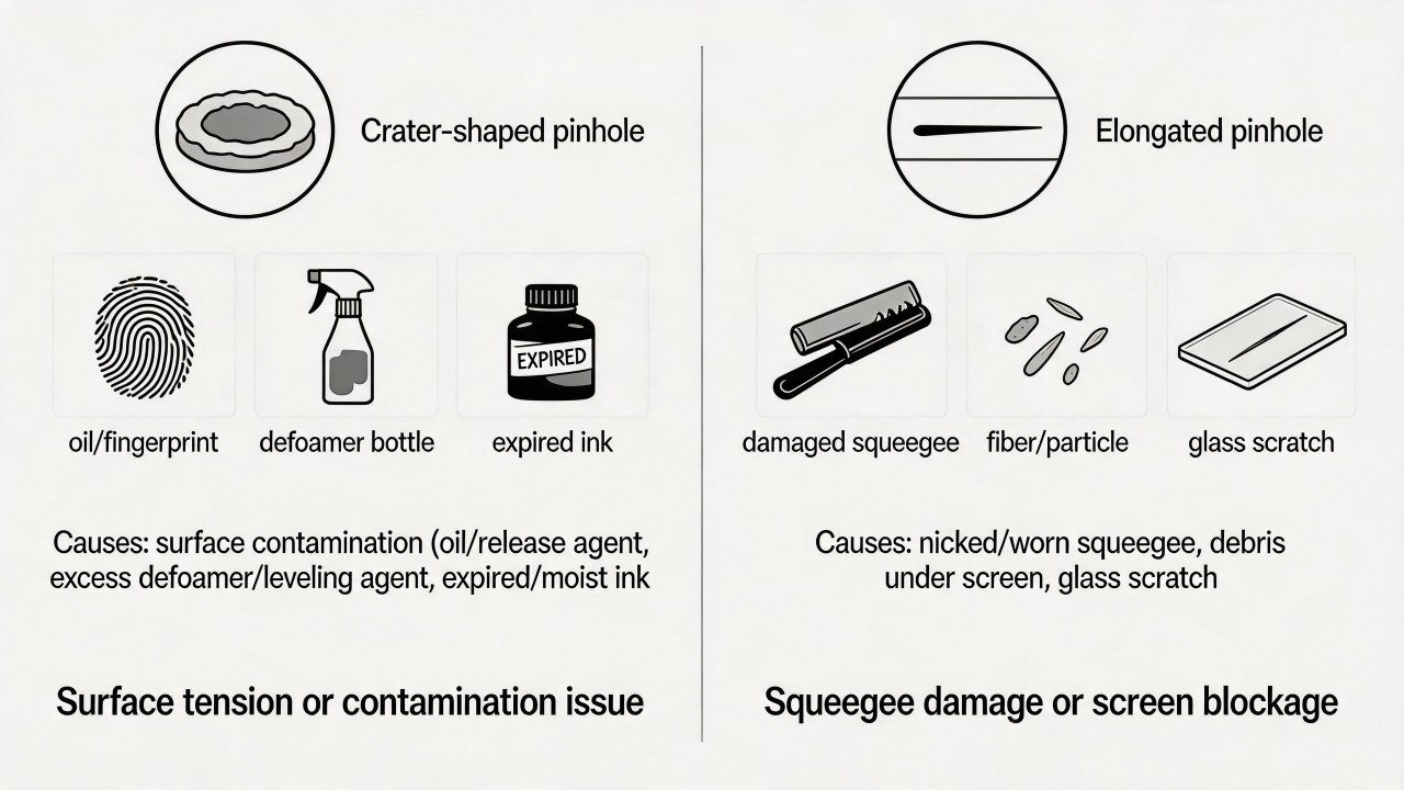 Crater-shaped pinholes (with a depressed center and a raised annular rim) typically indicate substrate surface contamination or surface tension problems with the ink. This type of pinhole is essentially a "crater"—the ink fails to spread evenly and is forced to recede, leaving a depression surrounded by a raised ring. The most common cause is the presence of oil, fingerprints, mold release residue, or silicone contamination on the glass surface; these low-surface-tension contaminants "push" the ink away, forming a crater-like depression. Another cause is the addition of excessive defoamer or leveling agent to the ink, causing an imbalance in the ink's own surface tension. Additionally, using expired ink or ink that has absorbed moisture can also produce this defect. The solution lies in thoroughly cleaning the glass surface, checking the ink mixing ratio, and replacing it with fresh ink.
Elongated pinholes (appearing as slender lines or comet-like streaks) typically indicate squeegee damage or screen blockage. These pinholes are often aligned with the print direction, suggesting the presence of a fixed "obstruction" that continuously scratches or blocks the ink path during the squeegee stroke. The most common cause is a nicked or worn squeegee blade, which leaves a thin, ink-free streak on the screen that transfers to the glass as an elongated pinhole. Another cause is slender fibers, hairs, or hard particles stuck to the underside of the screen; these debris block the mesh openings, preventing ink from depositing in that streak area as the squeegee passes. In addition, elongated scratches on the glass surface that ink cannot fill will also appear as elongated pinholes. The solution is to inspect and replace the squeegee, use adhesive tape to remove debris from the underside of the screen, and check the surface quality of the glass substrate.
Dense pinpoint pinholes (numerous tiny pinholes less than 0.2 mm in diameter, evenly distributed) typically indicate bubbles in the ink or environmental dust. These pinholes are numerous, small, and relatively uniformly distributed, suggesting that a large number of micro-bubbles became entrained in the ink and burst after printing, leaving pinholes. The cause is ink being stirred too quickly, entrapping air, combined with insufficient or incomplete deaeration. Another possibility is that the printing speed is too high, generating bubbles as the ink is sheared on the screen. Furthermore, if the pinholes vary in size and are randomly distributed, it could be due to insufficient workshop cleanliness, with fine airborne dust settling on the glass surface or the underside of the screen; the dust becomes enveloped in ink, transfers, and is later washed away, leaving small dots. The solution is to let the ink stand for 15–30 minutes after stirring to deaerate, or use a centrifugal deaerator; reduce the printing speed; and strengthen workshop cleanliness management.
Crater-shaped pinholes (with a depressed center and a raised annular rim) typically indicate substrate surface contamination or surface tension problems with the ink. This type of pinhole is essentially a "crater"—the ink fails to spread evenly and is forced to recede, leaving a depression surrounded by a raised ring. The most common cause is the presence of oil, fingerprints, mold release residue, or silicone contamination on the glass surface; these low-surface-tension contaminants "push" the ink away, forming a crater-like depression. Another cause is the addition of excessive defoamer or leveling agent to the ink, causing an imbalance in the ink's own surface tension. Additionally, using expired ink or ink that has absorbed moisture can also produce this defect. The solution lies in thoroughly cleaning the glass surface, checking the ink mixing ratio, and replacing it with fresh ink.
Elongated pinholes (appearing as slender lines or comet-like streaks) typically indicate squeegee damage or screen blockage. These pinholes are often aligned with the print direction, suggesting the presence of a fixed "obstruction" that continuously scratches or blocks the ink path during the squeegee stroke. The most common cause is a nicked or worn squeegee blade, which leaves a thin, ink-free streak on the screen that transfers to the glass as an elongated pinhole. Another cause is slender fibers, hairs, or hard particles stuck to the underside of the screen; these debris block the mesh openings, preventing ink from depositing in that streak area as the squeegee passes. In addition, elongated scratches on the glass surface that ink cannot fill will also appear as elongated pinholes. The solution is to inspect and replace the squeegee, use adhesive tape to remove debris from the underside of the screen, and check the surface quality of the glass substrate.
Dense pinpoint pinholes (numerous tiny pinholes less than 0.2 mm in diameter, evenly distributed) typically indicate bubbles in the ink or environmental dust. These pinholes are numerous, small, and relatively uniformly distributed, suggesting that a large number of micro-bubbles became entrained in the ink and burst after printing, leaving pinholes. The cause is ink being stirred too quickly, entrapping air, combined with insufficient or incomplete deaeration. Another possibility is that the printing speed is too high, generating bubbles as the ink is sheared on the screen. Furthermore, if the pinholes vary in size and are randomly distributed, it could be due to insufficient workshop cleanliness, with fine airborne dust settling on the glass surface or the underside of the screen; the dust becomes enveloped in ink, transfers, and is later washed away, leaving small dots. The solution is to let the ink stand for 15–30 minutes after stirring to deaerate, or use a centrifugal deaerator; reduce the printing speed; and strengthen workshop cleanliness management.
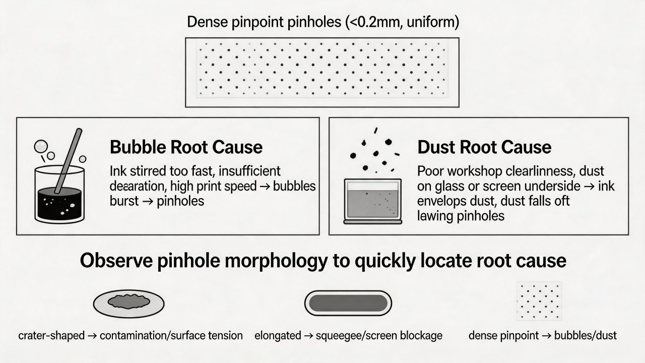 In summary, for crater-shaped pinholes, look for contamination and surface tension issues; for elongated pinholes, look at the squeegee and screen blockage; for dense pinpoint pinholes, look for bubbles and dust. By carefully observing the morphology of pinholes, the scope of investigation can be greatly narrowed, allowing the root cause to be identified quickly.
The cross-cut adhesion test passed, but peeling occurs after customer use—where should investigation begin?
When the cross-cut adhesion test passes yet peeling occurs during customer use, it indicates a gap between the laboratory quick test and the real-world usage environment. Investigation should proceed sequentially in the following five directions: Step 1: Re-examine whether the cross-cut test itself was truly "passed." In many cases, the test method harbors hidden misjudgments. First, confirm that the cut spacing matches the film thickness: typically, 1 mm spacing is used for films thinner than 50 μm, and 2 mm spacing for films thicker than 50 μm. If the spacing is too large, edge adhesion may not be effectively detected. Second, the tape used must be a standard-compliant high-tack tape (e.g., 3M 600 or 610); ordinary transparent tape lacks sufficient adhesion and may lead to a false "pass." Third, the peel angle should be 60° or 90°, not a perpendicular jerk, and the tape must be pressed down with a rubber roller before peeling. Finally, observe the delamination interface: if ink residue remains on the tape but ink is still present on the glass surface, it indicates cohesive failure within the ink layer; if the glass surface is completely free of ink, it indicates adhesive failure at the ink-glass interface. It is recommended to re-run the test in strict accordance with ISO 2409 and document the failure mode.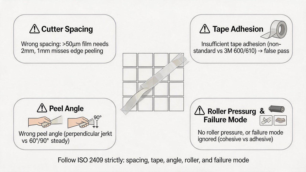 Step 2: Analyze the differences between the customer's usage conditions and the test environment. The cross-cut test is usually conducted under room-temperature, dry conditions, whereas the customer's application may involve the following stresses: temperature cycling (e.g., outdoor day-night temperature differences, thermal shock on oven door panels), high humidity (bathroom glass, kitchen environments), chemical contact (alcohol, cleaners, acidic or alkaline substances), mechanical abrasion (wiping, cleaning), and long-term UV exposure. For example, a low-temperature ink on glass may perform well in the cross-cut test, but after several thermal expansion and contraction cycles, accumulated interfacial stress leads to peeling. Therefore, it is necessary to obtain detailed information from the customer about the usage scenario and conduct targeted supplementary tests: such as damp heat aging (85°C/85% RH, 48 hours), temperature cycling (-40°C to 80°C, multiple cycles), alcohol wipe resistance (75% alcohol, 200 cycles), and salt spray testing. If peeling occurs in these tests, it indicates that the ink system itself lacks sufficient weatherability.
Step 3: Check whether the long-term chemical bonding between the ink and the glass is adequate. For ceramic inks requiring high-temperature sintering, a passed cross-cut test only indicates "adequate adhesion immediately after sintering." However, if the sintering temperature was too low or the holding time insufficient, the glass phase may not have fully melted. While initial adhesion may appear acceptable, in long-term use the interface will slowly hydrolyze due to water molecule penetration, leading to delayed peeling. It is advisable to perform accelerated aging tests on the same batch of products (e.g., boiling water immersion for 2 hours, or autoclave steam treatment) and observe whether peeling occurs. For low-temperature curing inks (such as UV-cured or two-component epoxy), adhesion relies primarily on physical bonding and is prone to degrade under hot and humid conditions; it is essential to verify whether the curing conditions (temperature, time, UV energy) meet the lower limits recommended by the supplier.
Step 2: Analyze the differences between the customer's usage conditions and the test environment. The cross-cut test is usually conducted under room-temperature, dry conditions, whereas the customer's application may involve the following stresses: temperature cycling (e.g., outdoor day-night temperature differences, thermal shock on oven door panels), high humidity (bathroom glass, kitchen environments), chemical contact (alcohol, cleaners, acidic or alkaline substances), mechanical abrasion (wiping, cleaning), and long-term UV exposure. For example, a low-temperature ink on glass may perform well in the cross-cut test, but after several thermal expansion and contraction cycles, accumulated interfacial stress leads to peeling. Therefore, it is necessary to obtain detailed information from the customer about the usage scenario and conduct targeted supplementary tests: such as damp heat aging (85°C/85% RH, 48 hours), temperature cycling (-40°C to 80°C, multiple cycles), alcohol wipe resistance (75% alcohol, 200 cycles), and salt spray testing. If peeling occurs in these tests, it indicates that the ink system itself lacks sufficient weatherability.
Step 3: Check whether the long-term chemical bonding between the ink and the glass is adequate. For ceramic inks requiring high-temperature sintering, a passed cross-cut test only indicates "adequate adhesion immediately after sintering." However, if the sintering temperature was too low or the holding time insufficient, the glass phase may not have fully melted. While initial adhesion may appear acceptable, in long-term use the interface will slowly hydrolyze due to water molecule penetration, leading to delayed peeling. It is advisable to perform accelerated aging tests on the same batch of products (e.g., boiling water immersion for 2 hours, or autoclave steam treatment) and observe whether peeling occurs. For low-temperature curing inks (such as UV-cured or two-component epoxy), adhesion relies primarily on physical bonding and is prone to degrade under hot and humid conditions; it is essential to verify whether the curing conditions (temperature, time, UV energy) meet the lower limits recommended by the supplier.
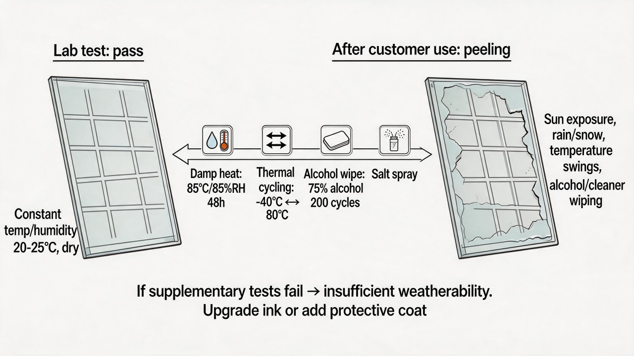 Step 4: Investigate the consistency of glass surface treatment. The piece of glass that passed the cross-cut test may have happened to have a good surface condition, but in mass production, there is a risk of mixing the "air side" and the "tin side" of the glass. When printing is performed on the tin side, residual tin ions can hinder the chemical bonding between the ink and the glass. Initial adhesion may barely pass, but after a period of use, these interfacial weak points will be the first to fail. It is recommended to use a contact angle meter or surface energy test pen to check the wettability of the glass surface and confirm that all products are printed on the air side. Furthermore, is the glass cleaning thorough? Has the cleaned glass been stored too long, leading to secondary contamination (dust, fingerprints)? These factors can all cause batch-to-batch instability in adhesion.
Step 5: Analyze the interfacial morphology after peeling. Use a microscope or magnifying glass to observe the glass surface in the peeled area: if a uniform, thin residue layer of ink remains on the glass surface, it indicates that the failure occurred within the ink layer itself (insufficient cohesive strength of the ink); if the glass surface is completely clean, it points to ink-glass interfacial failure; if irregular, patchy residues remain on the glass surface, it suggests localized contamination. At the same time, examine the edges of the peeled area for cracks or stress concentration marks, which may be related to micro-cracks introduced during subsequent glass processing (such as cutting, edge grinding, or drilling); these cracks can propagate during use and cause the ink to be peeled away along with them.
Step 4: Investigate the consistency of glass surface treatment. The piece of glass that passed the cross-cut test may have happened to have a good surface condition, but in mass production, there is a risk of mixing the "air side" and the "tin side" of the glass. When printing is performed on the tin side, residual tin ions can hinder the chemical bonding between the ink and the glass. Initial adhesion may barely pass, but after a period of use, these interfacial weak points will be the first to fail. It is recommended to use a contact angle meter or surface energy test pen to check the wettability of the glass surface and confirm that all products are printed on the air side. Furthermore, is the glass cleaning thorough? Has the cleaned glass been stored too long, leading to secondary contamination (dust, fingerprints)? These factors can all cause batch-to-batch instability in adhesion.
Step 5: Analyze the interfacial morphology after peeling. Use a microscope or magnifying glass to observe the glass surface in the peeled area: if a uniform, thin residue layer of ink remains on the glass surface, it indicates that the failure occurred within the ink layer itself (insufficient cohesive strength of the ink); if the glass surface is completely clean, it points to ink-glass interfacial failure; if irregular, patchy residues remain on the glass surface, it suggests localized contamination. At the same time, examine the edges of the peeled area for cracks or stress concentration marks, which may be related to micro-cracks introduced during subsequent glass processing (such as cutting, edge grinding, or drilling); these cracks can propagate during use and cause the ink to be peeled away along with them.
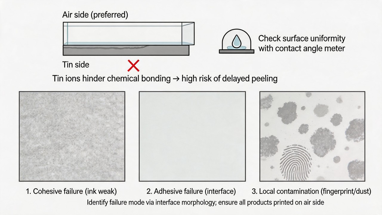 Summary of investigation sequence: first, verify the correctness of the cross-cut test method → then simulate the customer's usage conditions with supplementary tests → next, check whether the sintering or curing process is sufficient → then verify the consistency of glass surface treatment → finally, observe the failure interface morphology. Typically, 80% of such problems stem from a "mismatch between test conditions and usage conditions," meaning that the customer's hot-humid, chemical, or thermal cycling stresses expose the true durability shortcomings of the ink system. Therefore, the most direct improvement direction is to upgrade the ink system (e.g., switching to a high-temperature sintering-type ceramic ink) or to apply a protective topcoat.
Is edge jaggedness in printing a screen problem or a squeegee problem, and how can the two be quickly distinguished?
When jaggedness appears on printed edges, both the screen and the squeegee could be the culprit, but the key to quickly distinguishing them lies in observing the morphology of the jaggedness and whether it changes with variations in printing parameters. Jaggedness caused by screen problems is usually "inherent" and fixed, whereas jaggedness caused by squeegee problems tends to be "acquired" and variable.
Jaggedness caused by screen problems originates at the screen-making stage. The most typical case is when the weave pattern of the mesh threads is directly mapped onto the pattern edge; when the angle between fine lines and screen threads is inappropriate, the ink passing through the mesh openings forms step-like jaggedness. Another scenario is when the edge of the emulsion stencil itself is not straight and smooth, which may result from underexposure, overdevelopment, or blurred edges on the film positive. Such jaggedness is characterized by a regular shape, uniform spacing, alignment with the direction of the mesh weave, and—most importantly—the position and size of the jaggedness do not change noticeably regardless of how you adjust squeegee pressure, speed, or hardness. You can use a magnifying glass to examine the pattern edges on the screen; if jaggedness is already present on the screen, the problem is definitely with the screen. If the screen edges are smooth but the print exhibits jaggedness, the problem lies in the printing process.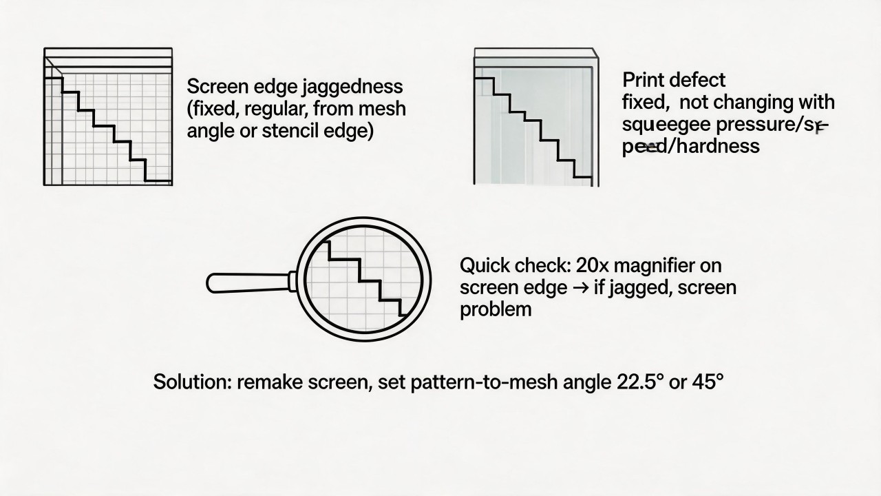 Jaggedness caused by squeegee problems differs in morphology from screen-related jaggedness. When the squeegee blade has nicks or wear, it leaves periodic longitudinal streaks or burr-like jaggedness aligned with the print direction; this jaggedness is often irregular, non-uniform in size, and randomly distributed. Insufficient squeegee pressure or an overly hard squeegee results in inadequate contact between the screen and the glass, and the ink is "dragged" into a jagged shape as it passes through the mesh openings; this type of jaggedness typically appears as trailing tails extending along the print direction. An excessively flat squeegee angle (too tilted) can also cause similar problems. This type of jaggedness is characterized by an irregular shape and variation with printing parameters. You can verify this with the following quick test: install a new squeegee, keep all other parameters unchanged, and print several sheets. If the jaggedness disappears or markedly improves, the original squeegee was the problem; if the jaggedness persists with unchanged shape and position, the problem lies with the screen.
Three-step rapid on-site differentiation method: First, examine the screen—use a magnifier of at least 20× to inspect the pattern edges on the screen; if the edges themselves show jaggedness or stepping, directly determine it as a screen problem and remake the screen (recommended to set the pattern-to-mesh angle at 22.5° or 45°). Second, change the squeegee—take a new squeegee (ensuring a straight blade edge and moderate hardness, e.g., 75A), install it, and print with the same parameters; if the jaggedness disappears or is noticeably reduced, determine it as a squeegee problem; if the jaggedness remains with unchanged shape and position, determine it as a screen problem. Third, adjust pressure—increase squeegee pressure by 20%–30% for a test print; if the jaggedness develops trailing tails or worsens burrs, the squeegee may be too hard or the pressure too high; if the jaggedness shows no change, the problem is more likely with the screen.
Jaggedness caused by squeegee problems differs in morphology from screen-related jaggedness. When the squeegee blade has nicks or wear, it leaves periodic longitudinal streaks or burr-like jaggedness aligned with the print direction; this jaggedness is often irregular, non-uniform in size, and randomly distributed. Insufficient squeegee pressure or an overly hard squeegee results in inadequate contact between the screen and the glass, and the ink is "dragged" into a jagged shape as it passes through the mesh openings; this type of jaggedness typically appears as trailing tails extending along the print direction. An excessively flat squeegee angle (too tilted) can also cause similar problems. This type of jaggedness is characterized by an irregular shape and variation with printing parameters. You can verify this with the following quick test: install a new squeegee, keep all other parameters unchanged, and print several sheets. If the jaggedness disappears or markedly improves, the original squeegee was the problem; if the jaggedness persists with unchanged shape and position, the problem lies with the screen.
Three-step rapid on-site differentiation method: First, examine the screen—use a magnifier of at least 20× to inspect the pattern edges on the screen; if the edges themselves show jaggedness or stepping, directly determine it as a screen problem and remake the screen (recommended to set the pattern-to-mesh angle at 22.5° or 45°). Second, change the squeegee—take a new squeegee (ensuring a straight blade edge and moderate hardness, e.g., 75A), install it, and print with the same parameters; if the jaggedness disappears or is noticeably reduced, determine it as a squeegee problem; if the jaggedness remains with unchanged shape and position, determine it as a screen problem. Third, adjust pressure—increase squeegee pressure by 20%–30% for a test print; if the jaggedness develops trailing tails or worsens burrs, the squeegee may be too hard or the pressure too high; if the jaggedness shows no change, the problem is more likely with the screen.
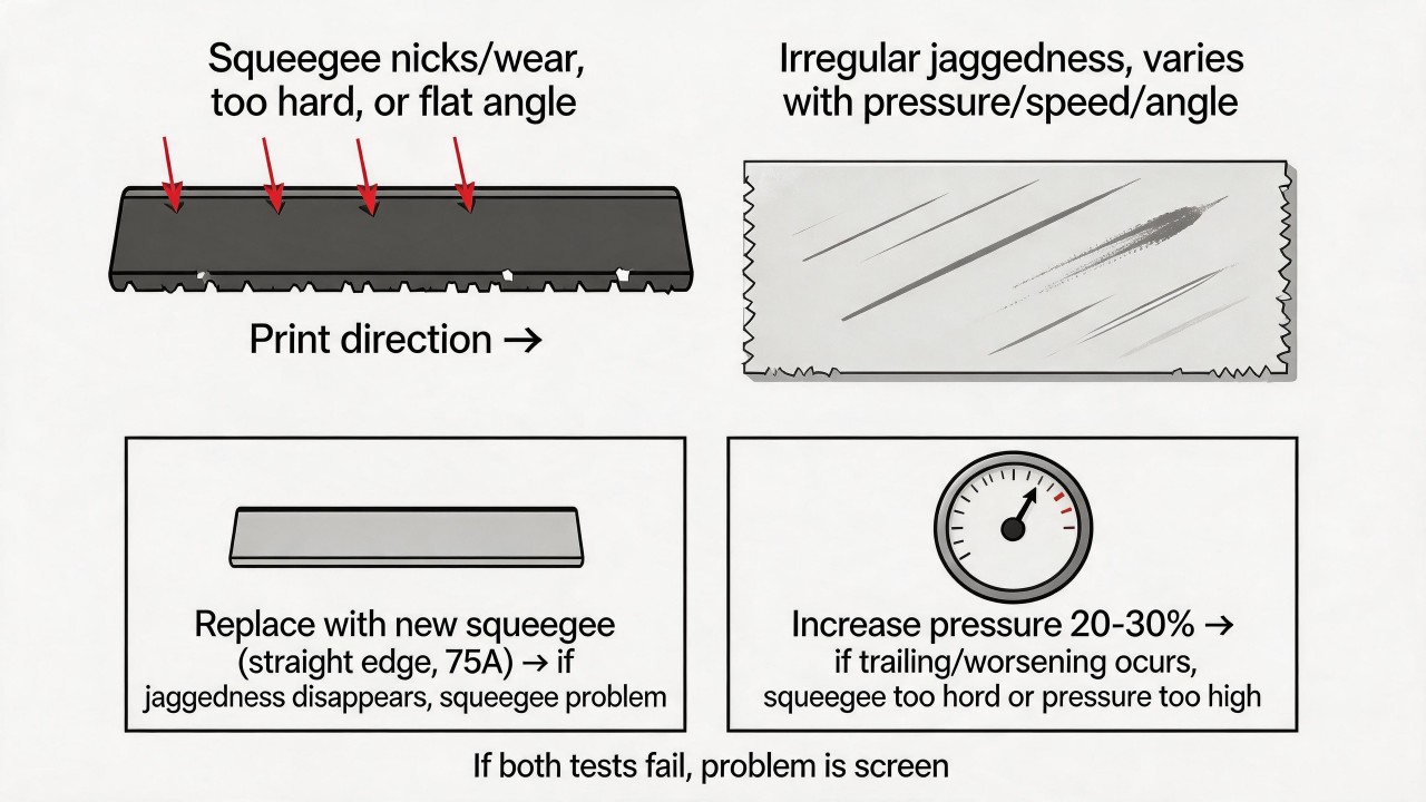 In summary, jaggedness originating from the screen is "structural"—fixed and regular; jaggedness originating from the squeegee is "process-related"—random and variable. First check the screen with a magnifier, then test with a new squeegee—these two steps will quickly pinpoint the root cause.
What residues could cause a “whitening” or “fogging” appearance on the pattern after sintering?
The appearance of “whitening” or “fogging” on glass after sintering is very likely due to residues from a certain stage being exposed at high temperatures. Based on experience, the most common residues include cleaning-related residues, plate-making and ink residues, environmental and handling contamination, as well as the influence of the sintering process or the glass material itself.
Cleaning-related residues are the most easily overlooked source of the problem. If the water used for cleaning the glass has high hardness, or if substances such as silicone oil or wax remain on the glass surface, stubborn white fog will form after high-temperature sintering; additionally, if the cleaning agent itself is not rinsed off thoroughly, it can also leave a white powdery residue. With regard to plate-making and ink residues, if the photosensitive emulsion on the screen is not completely removed, or if the solvent and thinner inside the screen after printing have not fully evaporated, these substances will undergo chemical changes during high-temperature sintering, forming an irregular white haze in the patterned area.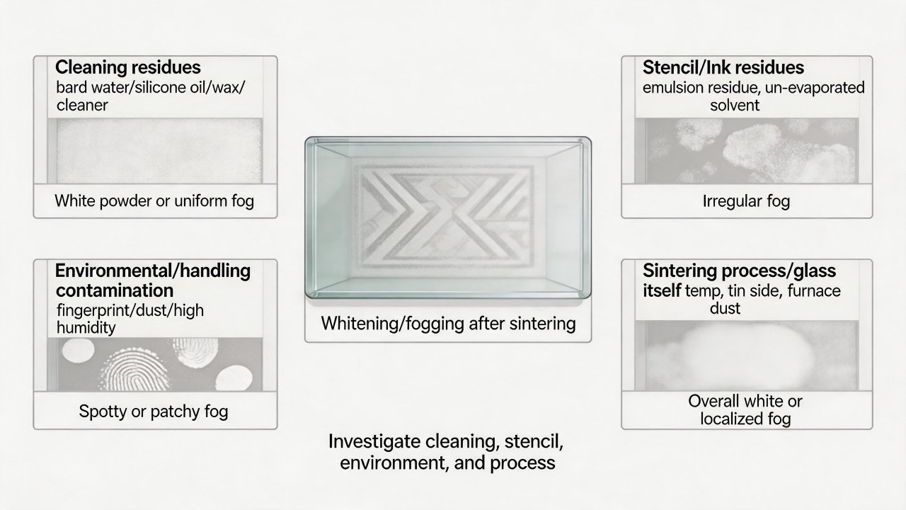 Environmental and handling contamination are also common causes. If the glass is not wiped clean before printing, residual fingerprints, oil marks, and dust, as well as excessive humidity in the workshop causing the ink to absorb moisture, will all leave pitting or fog-like marks after sintering.
Finally, insufficient sintering temperature can prevent the glass frit in the ink from fully fusing, resulting in a whitish fog; additionally, if the “tin side” of the glass is improperly treated or if there is dust inside the furnace, the surface can also become contaminated.
It is recommended to troubleshoot step by step in the order of “from easiest to hardest, from pre-printing to post-sintering.” Start with the simplest aspects, “water” and “cleaning,” focusing on checking the purity of the cleaning water (deionized water or purified water is recommended) and the cleaning agent formulation, ensuring thorough final rinsing. Then inspect the workshop environment and handling, confirming that the humidity in the printing workshop is around 50% and that the glass is thoroughly cleaned and free of oil and fingerprints before printing. Next, check the sintering process to confirm whether the sintering temperature and time meet the required standards; typically, high-temperature inks require a sintering temperature of 600–700°C. Finally, investigate the ink and screen, considering whether the ink itself has absorbed moisture and whether the plate-making emulsion has been completely removed.
Environmental and handling contamination are also common causes. If the glass is not wiped clean before printing, residual fingerprints, oil marks, and dust, as well as excessive humidity in the workshop causing the ink to absorb moisture, will all leave pitting or fog-like marks after sintering.
Finally, insufficient sintering temperature can prevent the glass frit in the ink from fully fusing, resulting in a whitish fog; additionally, if the “tin side” of the glass is improperly treated or if there is dust inside the furnace, the surface can also become contaminated.
It is recommended to troubleshoot step by step in the order of “from easiest to hardest, from pre-printing to post-sintering.” Start with the simplest aspects, “water” and “cleaning,” focusing on checking the purity of the cleaning water (deionized water or purified water is recommended) and the cleaning agent formulation, ensuring thorough final rinsing. Then inspect the workshop environment and handling, confirming that the humidity in the printing workshop is around 50% and that the glass is thoroughly cleaned and free of oil and fingerprints before printing. Next, check the sintering process to confirm whether the sintering temperature and time meet the required standards; typically, high-temperature inks require a sintering temperature of 600–700°C. Finally, investigate the ink and screen, considering whether the ink itself has absorbed moisture and whether the plate-making emulsion has been completely removed.
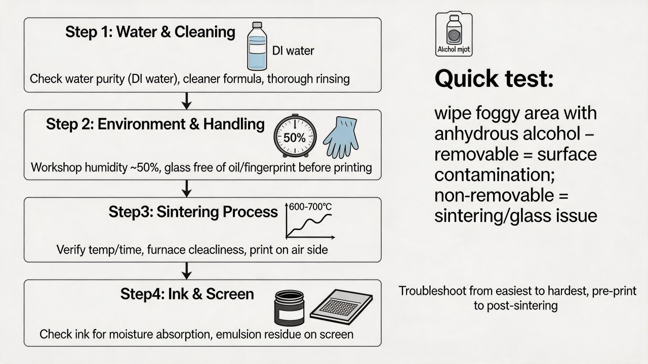 A simple verification method is to take a piece of the problem glass and carefully wipe the whitish/foggy area with anhydrous alcohol or a specialized cleaning agent. If it can be wiped off, it indicates that the residue is a contaminant adhering to the surface; if it cannot be wiped off, the problem is more likely with the sintering process or the glass material itself. If convenient, observe whether the whitish/foggy area is only where the ink is printed or across the entire glass surface; this information will help to more accurately determine the direction of the problem.
Why is there a noticeable color difference between the upper and lower glass sheets in the same furnace?
The most direct reason for the color difference between upper and lower glass sheets in the same furnace is the presence of a vertical temperature gradient within the furnace. Although the glass enters the furnace at what seems like the "same time," the seeds of uneven heating are planted during the heating stage and ultimately revealed when the ink is sintered. First, the different heating modes above and below in the tempering furnace are the root cause of the temperature difference. In a horizontal roller-hearth tempering furnace, the lower surface of the glass directly contacts the rollers and gains heat through thermal conduction, whereas the upper surface relies entirely on thermal radiation from the heating elements. These distinct heat transfer mechanisms inherently produce different heating rates. If the temperature difference between the upper and lower parts of the furnace chamber exceeds 10°C, the heat absorbed by the top and bottom surfaces of the glass will differ significantly. This temperature differential causes the ink (especially temperature-sensitive ceramic enamels) to sinter to different degrees, which ultimately manifests as a color difference.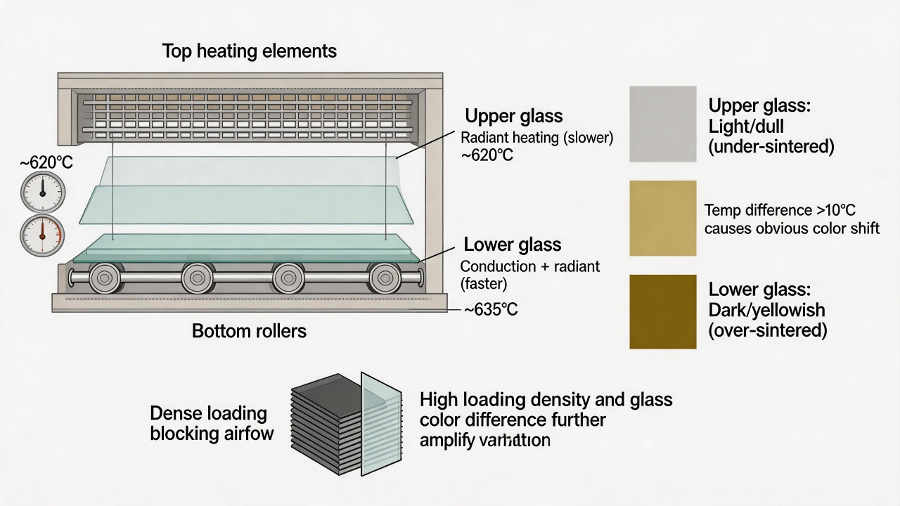 Secondly, furnace loading and convective gas flow further exacerbate the temperature gradient. When the upper layer of glass is large in quantity or densely arranged, the large sheets of cold glass act as a barrier that obstructs the rise and circulation of hot air within the furnace. This prevents the hot air above from effectively transferring heat to the uppermost glass, while heat tends to accumulate between the lower glass sheets. At the same time, the heat of the rollers themselves conducts to the lower glass, further widening the temperature difference between the top and bottom. The edges of the glass, which have a larger surface area in contact with the heat transfer medium, absorb heat more efficiently than the center; combined with the vertical temperature gradient, this characteristic makes the color difference problem even more complex.
Furthermore, the characteristics of the glass itself amplify the color difference. The color of the glass affects its heat absorption rate: dark-colored glass (e.g., deep blue, dark green) has strong heat absorptivity and heats up faster, whereas light-colored glass has weaker heat absorptivity and requires a higher furnace temperature or longer heating time. When this property is superimposed on the vertical temperature gradient inside the furnace, the color performance of different glass sheets after sintering in the same furnace becomes even more pronounced.
Secondly, furnace loading and convective gas flow further exacerbate the temperature gradient. When the upper layer of glass is large in quantity or densely arranged, the large sheets of cold glass act as a barrier that obstructs the rise and circulation of hot air within the furnace. This prevents the hot air above from effectively transferring heat to the uppermost glass, while heat tends to accumulate between the lower glass sheets. At the same time, the heat of the rollers themselves conducts to the lower glass, further widening the temperature difference between the top and bottom. The edges of the glass, which have a larger surface area in contact with the heat transfer medium, absorb heat more efficiently than the center; combined with the vertical temperature gradient, this characteristic makes the color difference problem even more complex.
Furthermore, the characteristics of the glass itself amplify the color difference. The color of the glass affects its heat absorption rate: dark-colored glass (e.g., deep blue, dark green) has strong heat absorptivity and heats up faster, whereas light-colored glass has weaker heat absorptivity and requires a higher furnace temperature or longer heating time. When this property is superimposed on the vertical temperature gradient inside the furnace, the color performance of different glass sheets after sintering in the same furnace becomes even more pronounced.How to prevent bubbles in ink that are invisible during printing but appear after sintering?
Bubbles that are invisible during printing but appear after sintering are often referred to as "hidden bubbles," and their root causes lie hidden within the ink, the substrate, or the sintering process. Such bubbles are mainly generated by two mechanisms: one is solvent bubbles, where the solvent in the ink fails to volatilize sufficiently during printing and becomes trapped within the ink film; during high-temperature sintering, the solvent rapidly vaporizes and expands, breaking through the partially cured ink surface to form "volcanic craters" or bubble marks. The other is outgassing bubbles, where the ink or glass substrate undergoes reactions at high temperatures that release gases (e.g., decomposition of organic matter, reactions of chemical raw materials), and as these gases escape, they leave bubbles in the softened ink film. To solve this problem, systematic investigation across multiple stages is required. The first is issues with the ink itself: stirring too fast or for too long can entrap air; if the ink is not allowed sufficient standing time for deaeration after stirring (15 to 30 minutes is recommended), bubbles will remain in the ink. Excessively high ink viscosity hinders the escape of bubbles, and using the wrong thinner, expired ink, or moisture-contaminated ink also easily generates bubbles. The presence of moisture or low-boiling-point solvents in the ink itself is also a common cause. Adding a defoamer (e.g., 0.1% to 1%) helps eliminate bubbles, but an excessive amount can instead cause foaming. Next are issues with the substrate. Residual dust, oil, or moisture on the glass surface can serve as nucleation sites for bubbles, especially in humid environments where condensed water vapor on the glass surface forms bubbles or white haze during sintering. Therefore, thoroughly cleaning the glass and ensuring its surface is clean and dry before printing is crucial. In some processes, preheating the substrate is adopted to obtain a smoother printing surface.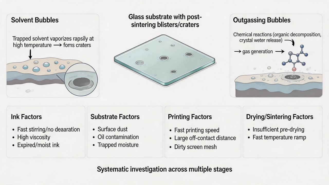 The printing process itself can also induce bubbles. Excessively fast printing speeds can "pull" bubbles out of the ink as the screen snaps off; appropriately reducing the speed and switching to a harder squeegee can help. An excessively large off-contact distance between the screen and the substrate makes it easier to entrap air during snap-off. Residual emulsion or inadequate cleaning on the screen can affect uniform ink transfer and may also lead to bubble formation.
The drying and sintering stage is one of the core causes. If the ink film is insufficiently dried before sintering, deep solvents vaporize and expand at high temperatures, or organic matter and water of crystallization in the ink release gases at high temperatures, all of which can form bubbles. Therefore, it is essential to ensure the ink film is completely dry before sintering, which can be achieved by extending the open time or low-temperature pre-baking (e.g., at 120–150°C). In addition, too rapid a temperature rise during sintering generates a large amount of gas instantaneously that has no time to escape; adopting a stepped heating profile and incorporating holding stages in critical temperature zones (e.g., the organic decomposition zone at 200–400°C) facilitates gradual gas release.
Environmental factors should not be overlooked. Excessively high workshop temperature and low humidity cause the solvent to volatilize too quickly, forming a surface skin on the ink film while the internal solvent cannot escape. It is recommended to control the workshop temperature at around 20°C and the relative humidity at around 60%.
The printing process itself can also induce bubbles. Excessively fast printing speeds can "pull" bubbles out of the ink as the screen snaps off; appropriately reducing the speed and switching to a harder squeegee can help. An excessively large off-contact distance between the screen and the substrate makes it easier to entrap air during snap-off. Residual emulsion or inadequate cleaning on the screen can affect uniform ink transfer and may also lead to bubble formation.
The drying and sintering stage is one of the core causes. If the ink film is insufficiently dried before sintering, deep solvents vaporize and expand at high temperatures, or organic matter and water of crystallization in the ink release gases at high temperatures, all of which can form bubbles. Therefore, it is essential to ensure the ink film is completely dry before sintering, which can be achieved by extending the open time or low-temperature pre-baking (e.g., at 120–150°C). In addition, too rapid a temperature rise during sintering generates a large amount of gas instantaneously that has no time to escape; adopting a stepped heating profile and incorporating holding stages in critical temperature zones (e.g., the organic decomposition zone at 200–400°C) facilitates gradual gas release.
Environmental factors should not be overlooked. Excessively high workshop temperature and low humidity cause the solvent to volatilize too quickly, forming a surface skin on the ink film while the internal solvent cannot escape. It is recommended to control the workshop temperature at around 20°C and the relative humidity at around 60%.
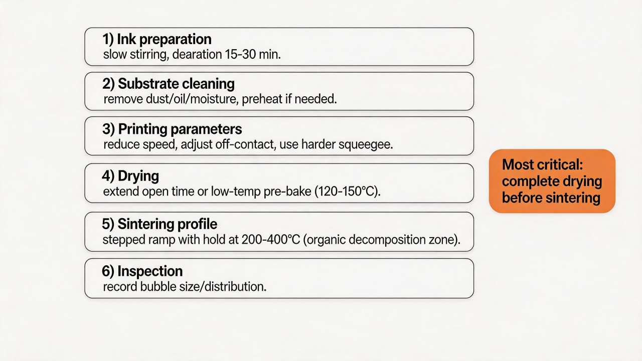 A systematic prevention plan includes: optimizing the stirring process, always allowing sufficient standing time for deaeration after using a mixer, with experienced operators using warm water to assist deaeration; strictly controlling ink storage and usage, rigorously checking expiration dates, using the manufacturer’s recommended thinner at the specified ratio, and avoiding cross-mixing; strengthening substrate cleaning, and adding dehumidification equipment in humidity-sensitive environments; standardizing printing parameters, finding and fixing the optimal printing speed and off-contact distance, and regularly inspecting squeegee condition and replacing as needed; ensuring thorough drying, guaranteeing the ink film is completely dry before sintering and reinforcing this through low-temperature pre-baking; optimizing the sintering profile by setting holding stages in critical temperature zones and reducing the heating rate; and establishing a process record sheet, documenting parameters such as ink viscosity, drying time, and sintering profile for each batch, and when problems arise, recording the size, distribution, and location of bubbles to facilitate rapid root cause tracing.
In summary, bubbles that are invisible during printing but appear after sintering are often the combined result of multiple factors spanning the ink, substrate, printing, drying, and sintering stages, with the most critical step being thorough drying before sintering. Solving this problem requires systematic investigation and prevention rather than a single remedial measure. By establishing standardized process workflows, this "hidden" quality risk can be effectively controlled and ultimately eliminated.
A systematic prevention plan includes: optimizing the stirring process, always allowing sufficient standing time for deaeration after using a mixer, with experienced operators using warm water to assist deaeration; strictly controlling ink storage and usage, rigorously checking expiration dates, using the manufacturer’s recommended thinner at the specified ratio, and avoiding cross-mixing; strengthening substrate cleaning, and adding dehumidification equipment in humidity-sensitive environments; standardizing printing parameters, finding and fixing the optimal printing speed and off-contact distance, and regularly inspecting squeegee condition and replacing as needed; ensuring thorough drying, guaranteeing the ink film is completely dry before sintering and reinforcing this through low-temperature pre-baking; optimizing the sintering profile by setting holding stages in critical temperature zones and reducing the heating rate; and establishing a process record sheet, documenting parameters such as ink viscosity, drying time, and sintering profile for each batch, and when problems arise, recording the size, distribution, and location of bubbles to facilitate rapid root cause tracing.
In summary, bubbles that are invisible during printing but appear after sintering are often the combined result of multiple factors spanning the ink, substrate, printing, drying, and sintering stages, with the most critical step being thorough drying before sintering. Solving this problem requires systematic investigation and prevention rather than a single remedial measure. By establishing standardized process workflows, this "hidden" quality risk can be effectively controlled and ultimately eliminated.
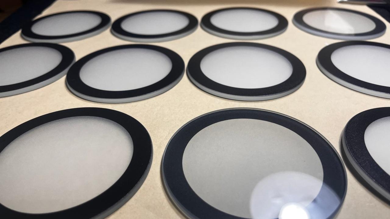
The contact angle test after glass cleaning is normal, yet craters still appear during printing—what else has been overlooked?
In glass screen printing, when the contact angle test is normal but craters still occur, it usually means the root cause lies not in macroscopic cleanliness but in more subtle, microscopic factors. It is like an iceberg: the contact angle test only sees the tip above the water, while the problems beneath the surface are the key. One of the most common and easily overlooked causes is the "invisible residue" from cleaning agents or additives. Even if there are no particulates on the glass surface, components such as surfactants or silicone oils in the cleaning agent can form an ultra-thin, invisible film that alters the surface energy and creates a "barrier layer" between the ink and the glass, preventing the ink from spreading evenly and leading to craters. It is recommended to check the cleaning agent formulation, use silicone-free, readily volatile, environmentally friendly cleaning agents, rinse thoroughly with pure water after cleaning, or wipe the glass surface again with a lint-free cloth moistened with isopropyl alcohol to remove potential residues. "Self-conflict" within the ink system is also a common cause. If the defoamer dosage is inappropriate (e.g., exceeding 0.1% to 1%), it may instead induce cratering. Expired ink or ink that has not been thoroughly mixed may have uneven composition, leading to localized surface tension anomalies. Solvent evaporating too quickly can cause a high-surface-tension "skin" to form rapidly on the ink surface, preventing the underlying ink from leveling and thereby forming craters. It is recommended to add an appropriate amount of slow-drying solvent to the ink and strictly check the ink's shelf life and mixing uniformity.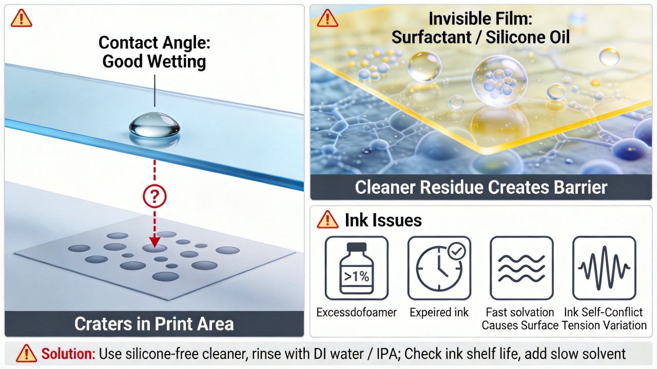 Minor interference from the environment and process can also cause craters. Tiny airborne oil mist, silicone oil particulates, and other low-surface-tension contaminants, once they land on the glass or screen, become "seeds" for craters, and because they are so minute, they will not affect the macroscopic contact angle reading. Furthermore, if airflow in the workshop (e.g., from air conditioning or personnel movement) blows directly onto the undried ink film, it accelerates surface solvent evaporation, raising the local surface tension and leading to craters. It is recommended to maintain positive pressure in the workshop and install high-efficiency filtration systems, ensuring stable airflow in the printing area with no strong drafts blowing directly.
Physical interference from the screen and squeegee should not be overlooked. Residual emulsion, ink particles, or dust on the screen can clog localized mesh openings, leading to uneven ink transfer and forming defects resembling craters. Improper squeegee pressure or angle can also cause uneven ink transfer, resulting in craters in areas where the ink film is thinner due to surface tension effects. It is recommended to wipe the screen with a lint-free cloth moistened with thinner before printing, and to check whether the squeegee blade is straight and the pressure is uniform.
The "inherent differences" of the glass itself sometimes play the role of the hidden culprit. In the production of float glass, the "tin side" that contacts the molten tin bath may retain trace tin ions; printing on the tin side allows these ions to interfere with the ink's adhesion, causing craters, whereas the "air side" of the glass is usually more suitable for printing and can be distinguished by inspection under a UV lamp. Additionally, extremely fine scratches or grinding residues on the glass surface can also alter the local flow behavior of the ink and induce craters.
Minor interference from the environment and process can also cause craters. Tiny airborne oil mist, silicone oil particulates, and other low-surface-tension contaminants, once they land on the glass or screen, become "seeds" for craters, and because they are so minute, they will not affect the macroscopic contact angle reading. Furthermore, if airflow in the workshop (e.g., from air conditioning or personnel movement) blows directly onto the undried ink film, it accelerates surface solvent evaporation, raising the local surface tension and leading to craters. It is recommended to maintain positive pressure in the workshop and install high-efficiency filtration systems, ensuring stable airflow in the printing area with no strong drafts blowing directly.
Physical interference from the screen and squeegee should not be overlooked. Residual emulsion, ink particles, or dust on the screen can clog localized mesh openings, leading to uneven ink transfer and forming defects resembling craters. Improper squeegee pressure or angle can also cause uneven ink transfer, resulting in craters in areas where the ink film is thinner due to surface tension effects. It is recommended to wipe the screen with a lint-free cloth moistened with thinner before printing, and to check whether the squeegee blade is straight and the pressure is uniform.
The "inherent differences" of the glass itself sometimes play the role of the hidden culprit. In the production of float glass, the "tin side" that contacts the molten tin bath may retain trace tin ions; printing on the tin side allows these ions to interfere with the ink's adhesion, causing craters, whereas the "air side" of the glass is usually more suitable for printing and can be distinguished by inspection under a UV lamp. Additionally, extremely fine scratches or grinding residues on the glass surface can also alter the local flow behavior of the ink and induce craters.
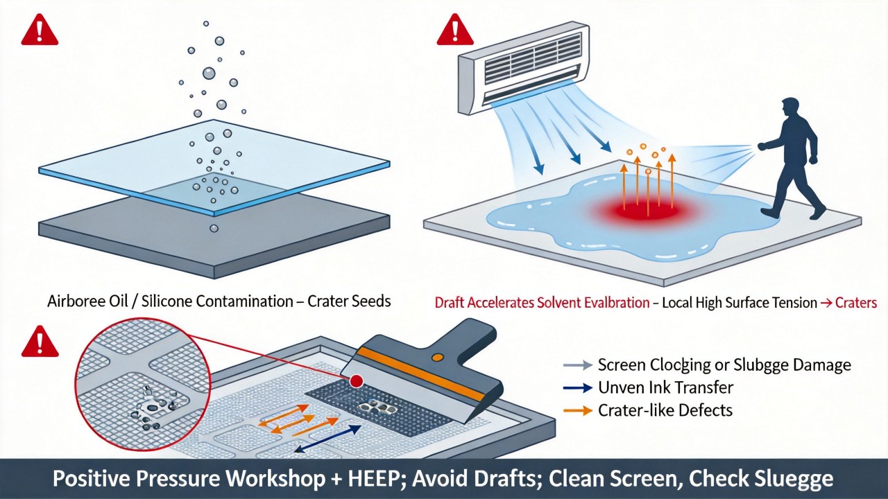 If routine investigation cannot locate the problem, more sophisticated inspection tools can be introduced. An optical microscope can observe the morphology of the craters to distinguish whether they are caused by contaminants (with a core) or bubbles (hollow); an atomic force microscope can detect nanoscale surface topography to find minute contaminants or unevenness; time-of-flight secondary ion mass spectrometry and infrared spectroscopy can identify the chemical composition of trace contaminants; dyne pens can quickly test surface tension on-site, but they need to be used in conjunction with water contact angle measurement and cannot detect trace contamination. These advanced diagnostic tools can help find the hidden root cause.
In summary, when the contact angle test is normal but craters persist, it is recommended to conduct a systematic investigation in the following order: first, check for cleaning agent and additive residues, and switch to pure water or isopropyl alcohol for the final rinse; next, check the condition of the ink, confirming the shelf life, mixing uniformity, and whether the defoamer and solvents are appropriate; then, investigate the environment and process, ensuring stable workshop airflow, temperature, and humidity; after that, clean the screen and check the squeegee condition; finally, confirm whether the printing surface of the glass is the air side and examine the surface for microscopic damage. It is recommended to use a controlled variable method to adjust parameters one at a time, and after each adjustment, conduct a test print to observe whether the craters improve. Through systematic investigation, this "invisible" quality issue can usually be identified and resolved. If convenient, observing the morphology of the craters (whether they are single round dots or have tails) or providing information on the type of ink and cleaning agent currently in use can help with a more precise analysis.
If routine investigation cannot locate the problem, more sophisticated inspection tools can be introduced. An optical microscope can observe the morphology of the craters to distinguish whether they are caused by contaminants (with a core) or bubbles (hollow); an atomic force microscope can detect nanoscale surface topography to find minute contaminants or unevenness; time-of-flight secondary ion mass spectrometry and infrared spectroscopy can identify the chemical composition of trace contaminants; dyne pens can quickly test surface tension on-site, but they need to be used in conjunction with water contact angle measurement and cannot detect trace contamination. These advanced diagnostic tools can help find the hidden root cause.
In summary, when the contact angle test is normal but craters persist, it is recommended to conduct a systematic investigation in the following order: first, check for cleaning agent and additive residues, and switch to pure water or isopropyl alcohol for the final rinse; next, check the condition of the ink, confirming the shelf life, mixing uniformity, and whether the defoamer and solvents are appropriate; then, investigate the environment and process, ensuring stable workshop airflow, temperature, and humidity; after that, clean the screen and check the squeegee condition; finally, confirm whether the printing surface of the glass is the air side and examine the surface for microscopic damage. It is recommended to use a controlled variable method to adjust parameters one at a time, and after each adjustment, conduct a test print to observe whether the craters improve. Through systematic investigation, this "invisible" quality issue can usually be identified and resolved. If convenient, observing the morphology of the craters (whether they are single round dots or have tails) or providing information on the type of ink and cleaning agent currently in use can help with a more precise analysis.
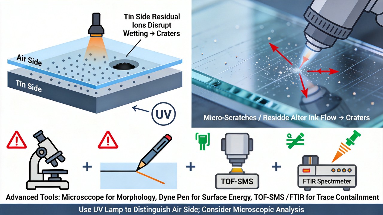
Contact Us
Your feedback fuels our growth, and your questions drive our solutions.
We value your feedback, inquiries, and suggestions. Please feel free to get in touch with us
General inquiries
Please contact us via sales@bo-glass.com, and we will reply to you as soon as possible.
Interested to work with us
Drop your resume at info@bo-glass.com
and we will get back to you shortly.
We uses the contact information you provide to us to contact you about our relevent content, products, and services.