
Glass Screen Printing Defects and Troubleshooting
Read the defect signature, preserve evidence, isolate variables and verify the correction.
Engineering note: Typical starting values are provided for reference. Final tolerances and process parameters should be confirmed through sample trials using the specified glass, ink system, artwork and firing conditions.
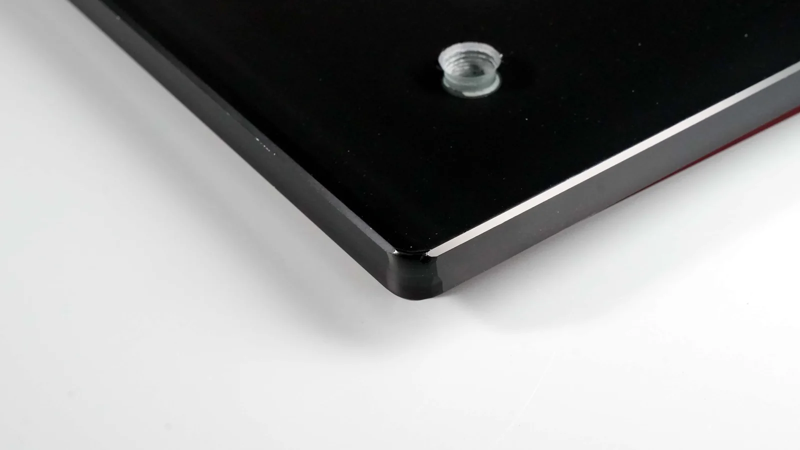
Contain first, then build a cause map
Stop mixing suspect and accepted material. Identify the last known-good check and segregate production since that point. Photograph the defect under a reproducible condition, mark its position and preserve representative parts. A washed or reprinted sample can destroy the evidence needed to find the cause.
Classify the defect by shape, location, frequency, orientation and process stage. Ask whether it follows the glass, screen, fixture, squeegee, press direction, furnace position, operator or time since ink preparation. A cause map is stronger than a list of generic remedies.
Change one variable at a time when safe. Use a known-good reference for screens, squeegees, ink or glass. Confirm the correction over enough parts and time to show that the failure mode is controlled, then update the control plan.
- What changed since the last accepted lot?
- Is the defect present wet, after cure, after firing or only after customer exposure?
- Does the defect repeat at the same artwork or part coordinate?
- Can it be measured by size, count, density, position or color?
- What evidence would disprove the leading cause?
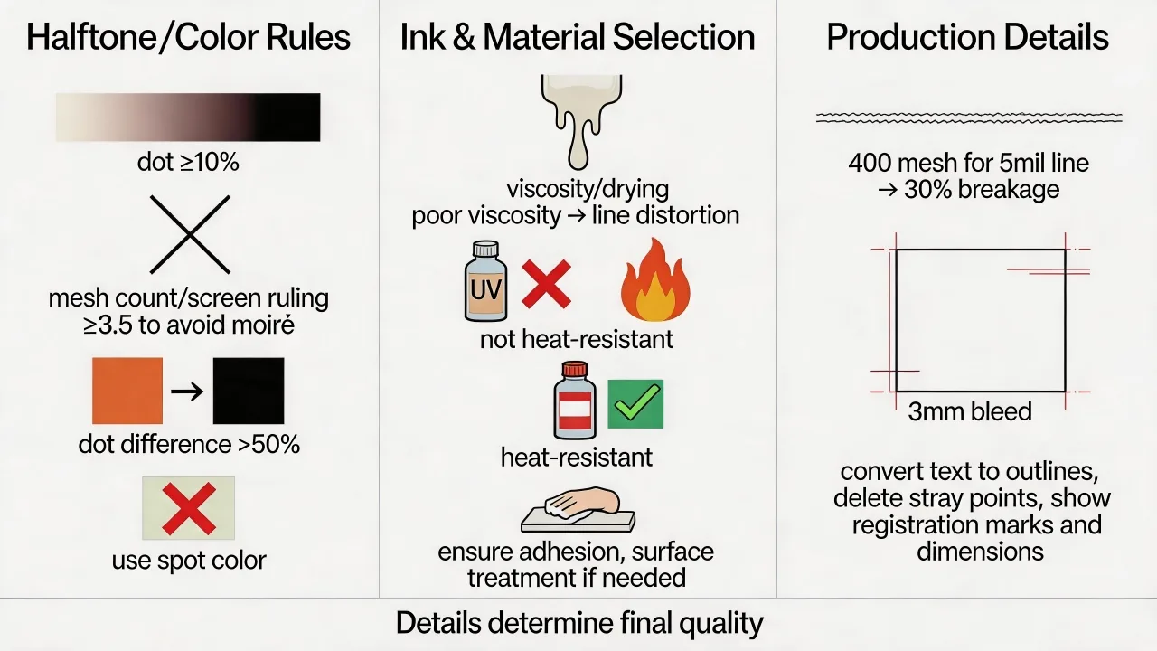
Use morphology as a clue, not a verdict
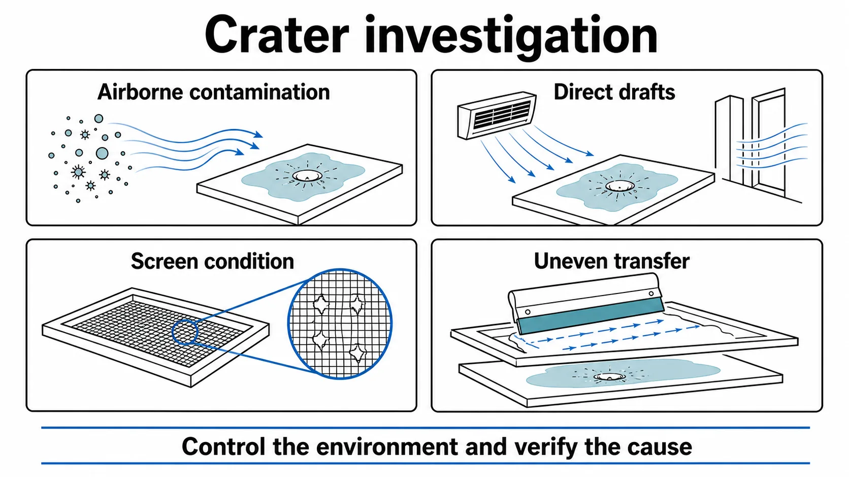
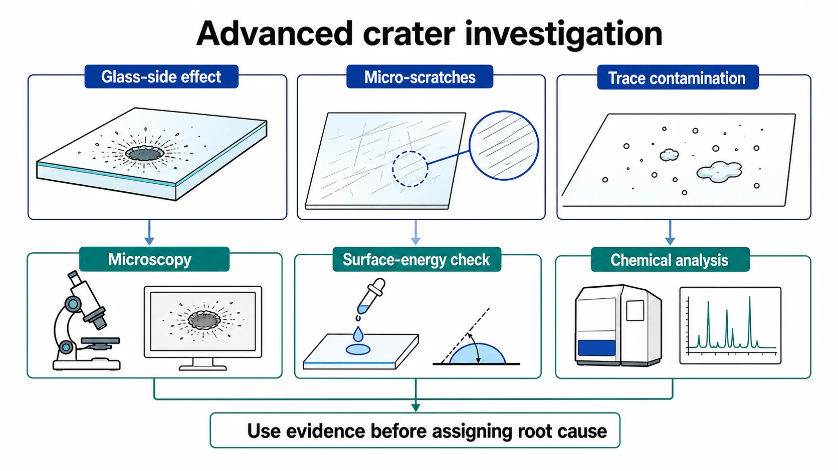
Round craters with raised rims may suggest dewetting or contamination; elongated voids may align with the print stroke, screen release or a fiber; dense fine points may relate to particles, foam, insufficient coverage, trapped gas or firing behavior. These associations are useful hypotheses, not diagnoses.
Inspect the glass before printing, the wet print and the cured or fired result. If a defect appears only after firing, consider vehicle release, film thickness, drying, enamel condition and thermal profile in addition to surface cleanliness. Bubbles invisible in the wet film can grow when gases cannot escape.
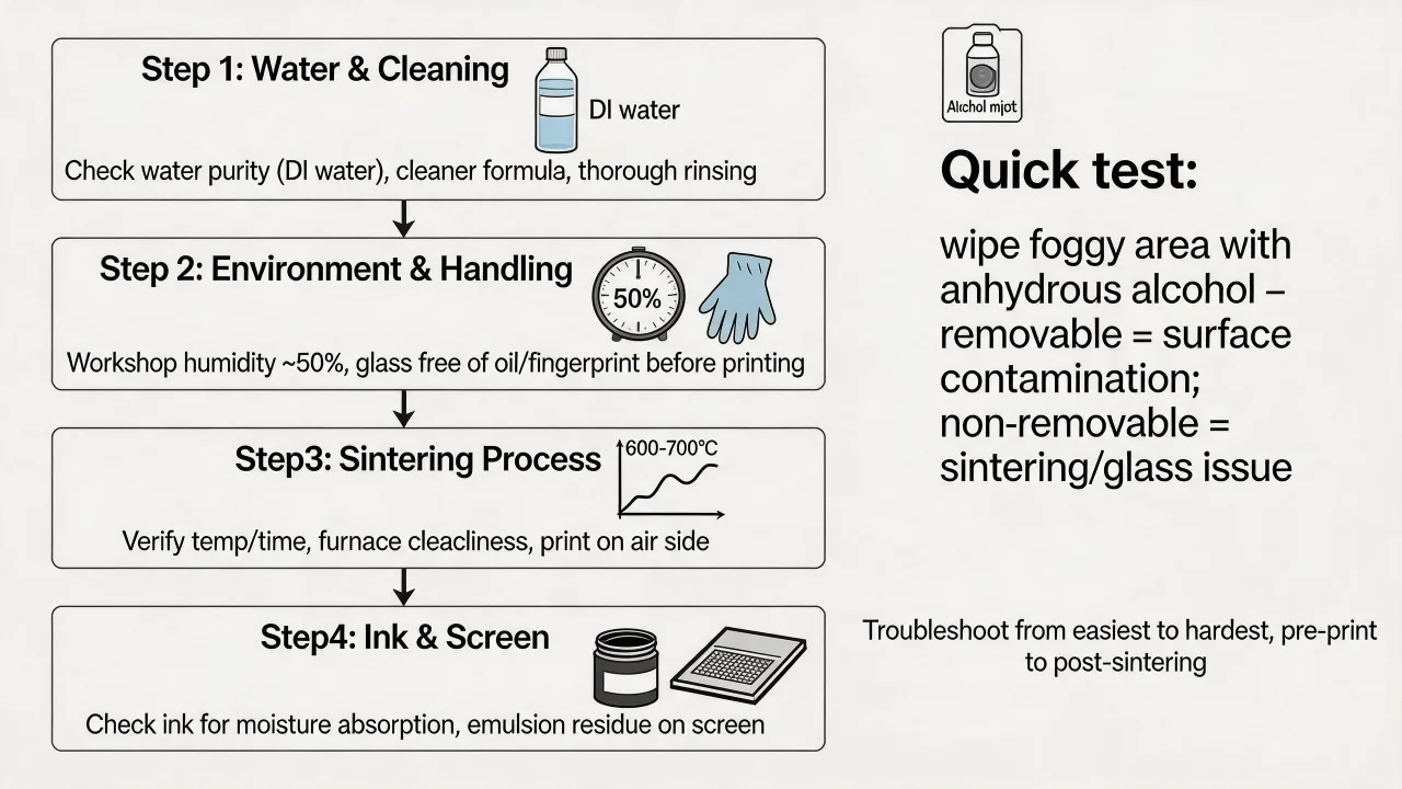
A normal contact-angle result does not clear every contamination mechanism. Sampling may miss a local silicone spot, cleaning residues can have similar average wetting, and particles may be deposited after the test. Audit handling, gloves, racks, air, screen and maintenance aerosols.
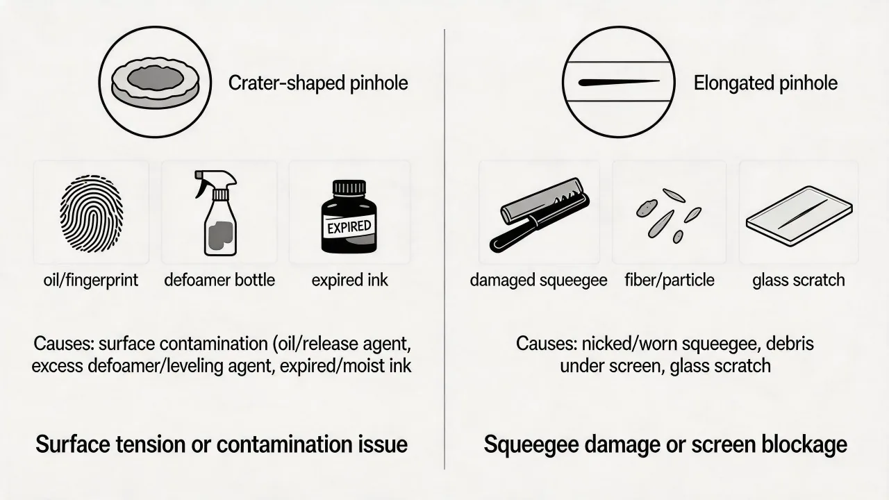
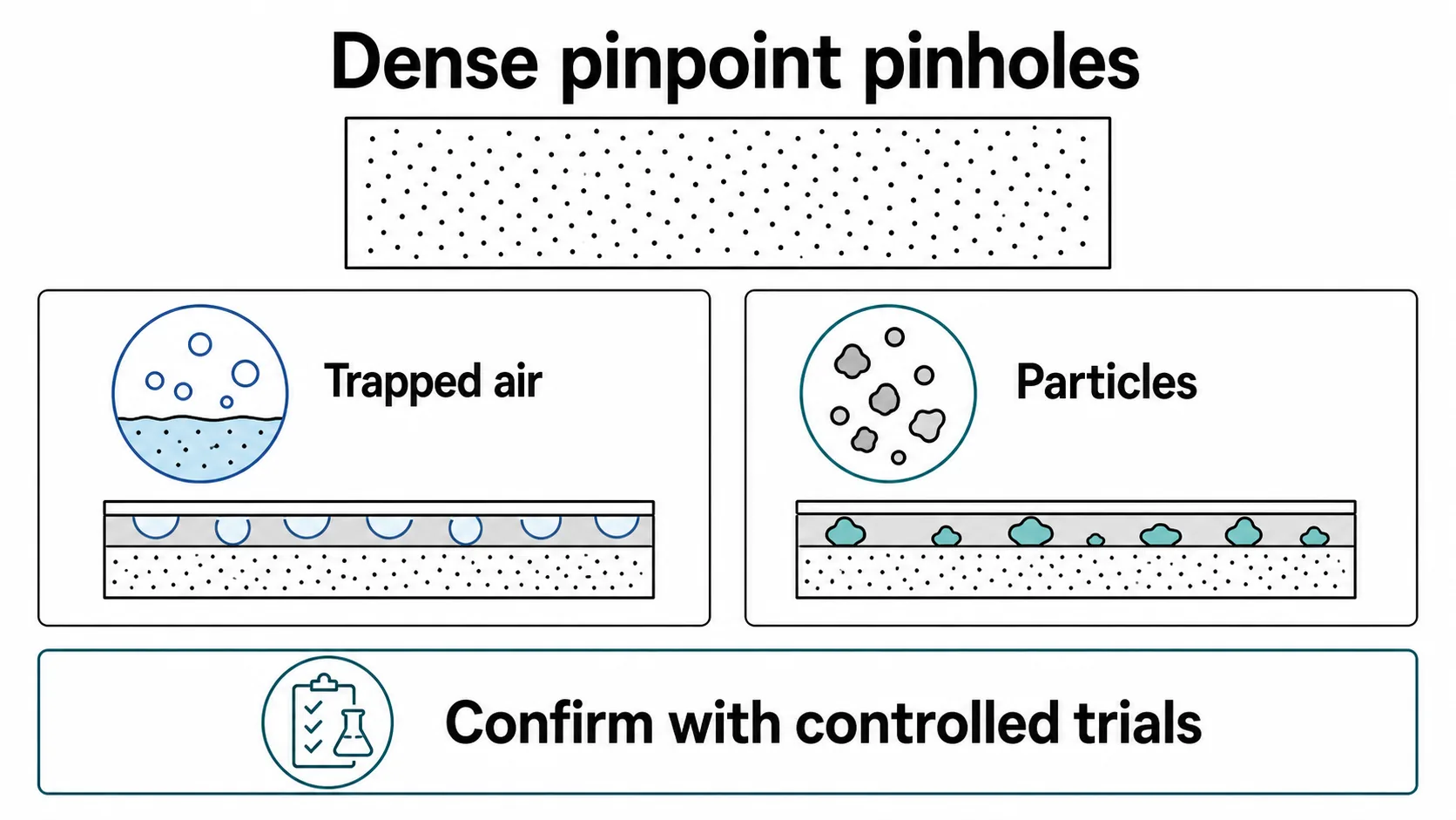
Additional pinhole and crater investigation diagrams
Use these images to broaden the cause map; do not treat any embedded setting as a universal acceptance value.
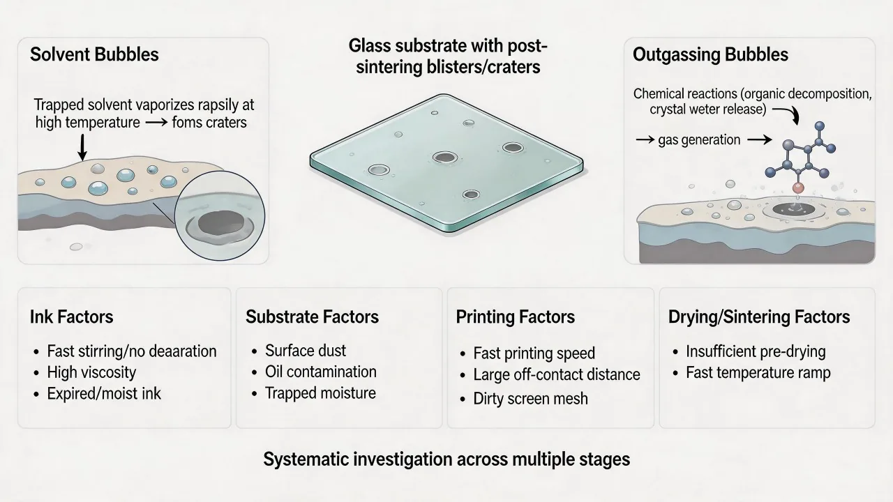
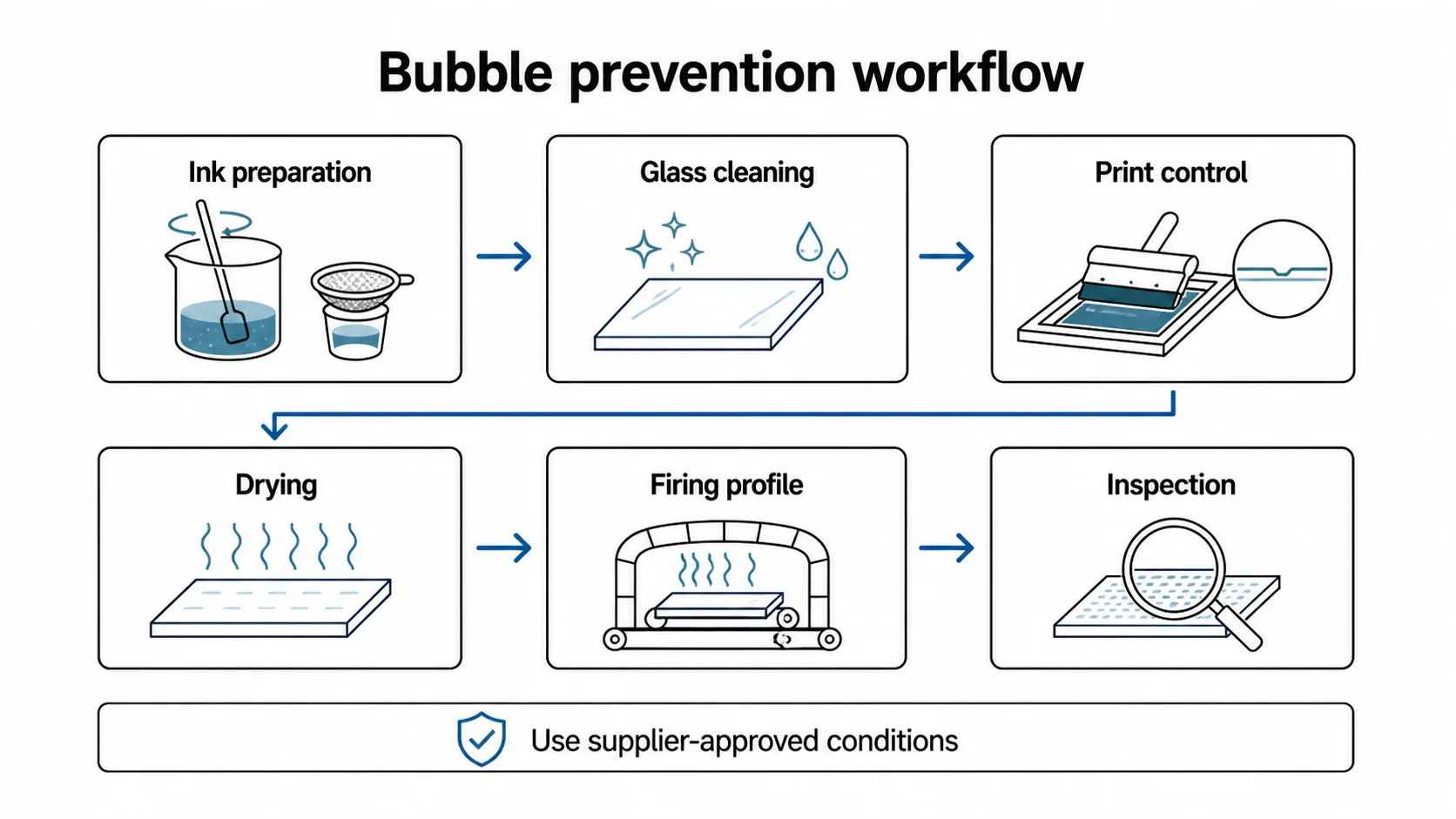
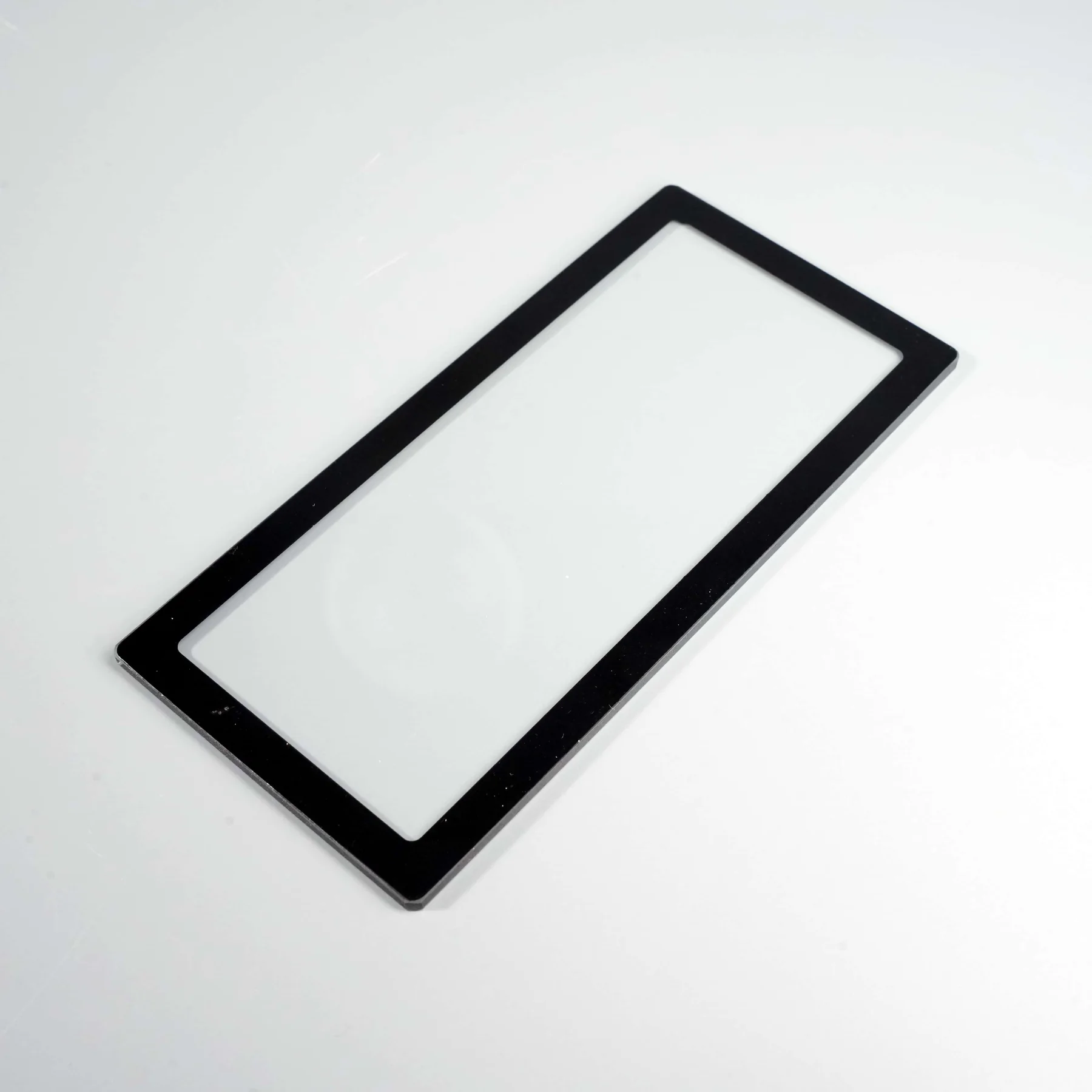
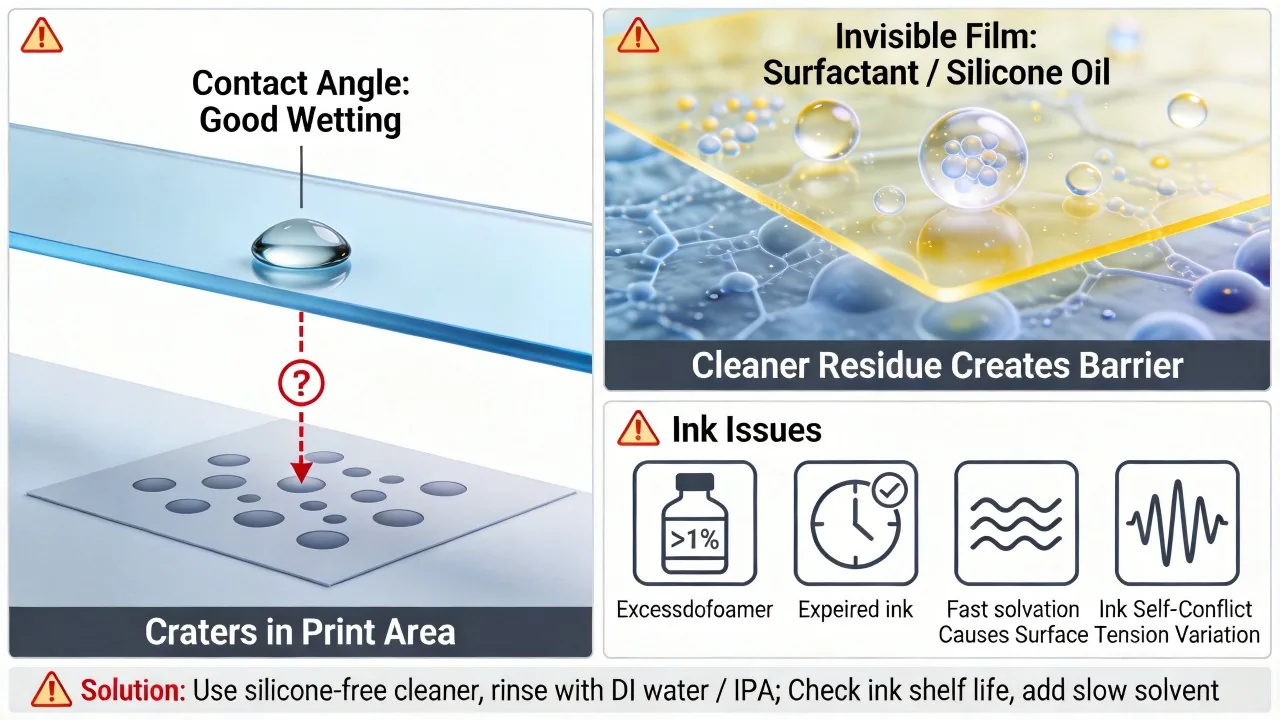
Separate stencil signatures from stroke signatures
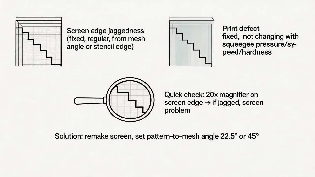
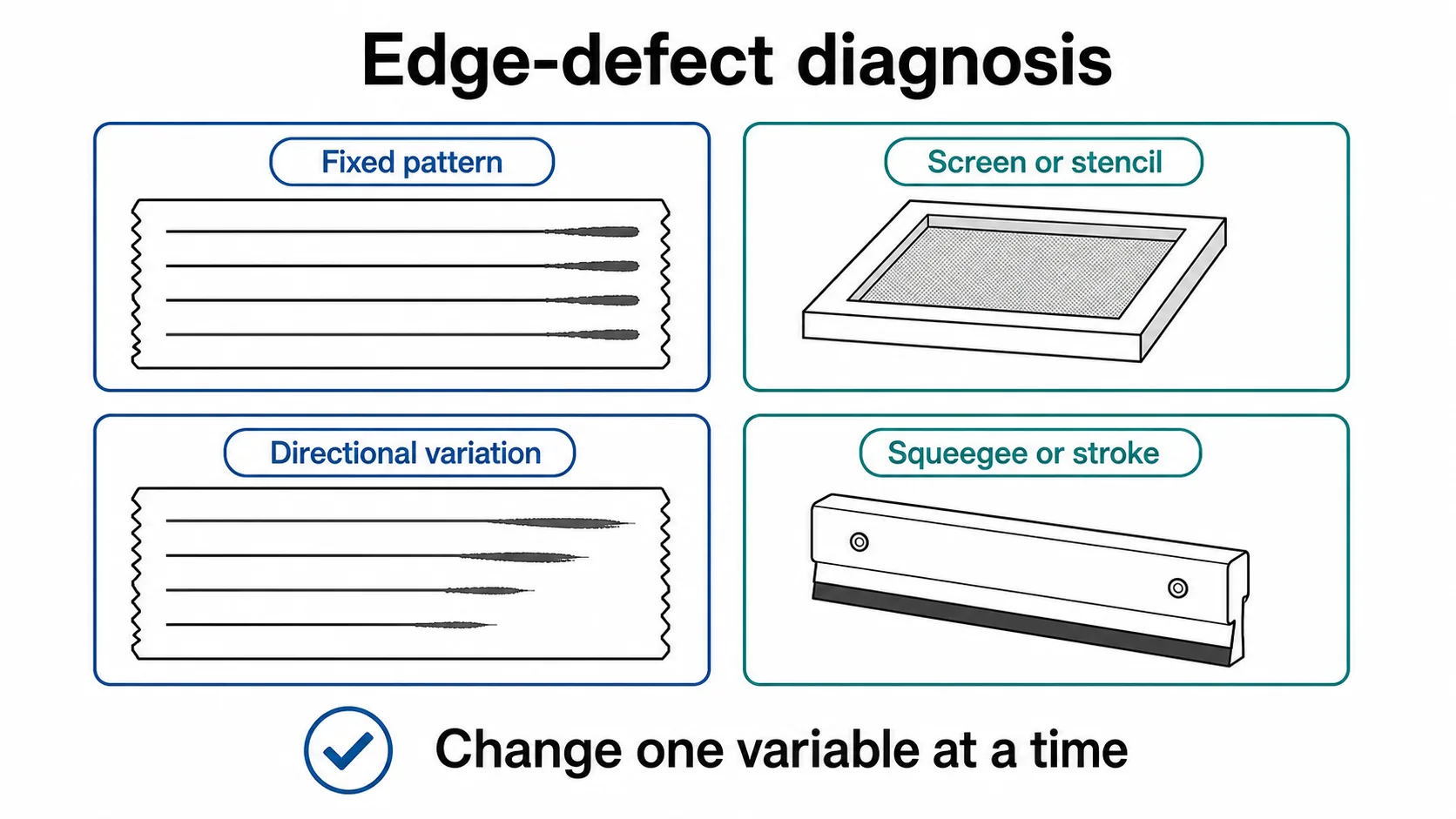
A jagged edge that repeats at the same image coordinate on every print points toward positive, stencil or mesh reproduction. An edge that changes with stroke direction, speed or blade substitution points more strongly toward print mechanics or rheology. Magnified comparison of the screen opening and wet print is often decisive.
Check stencil thickness, exposure contact, washout, mesh orientation and blocked openings. Then check squeegee edge, pressure, angle, speed, off-contact, snap-off and ink condition. Do not compensate for a damaged stencil by adding pressure; the change may hide one symptom and create smearing or deposit variation.
Ghost images after cleaning can partially block mesh, alter wetting or contaminate a new ink. Confirm whether the residue is physical blockage, stained mesh or chemical contamination. Reclaim using a qualified process and inspect before recoating. A cosmetic stain that does not affect openings is different from a deposit that changes flow.
A passed tape test does not close the investigation
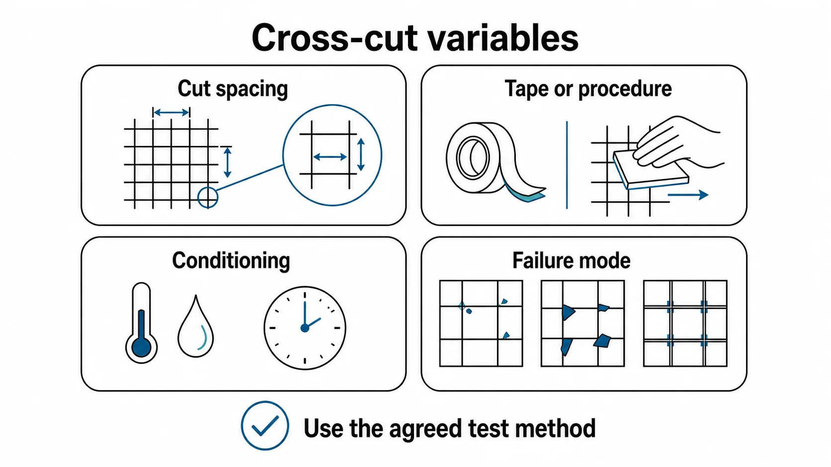
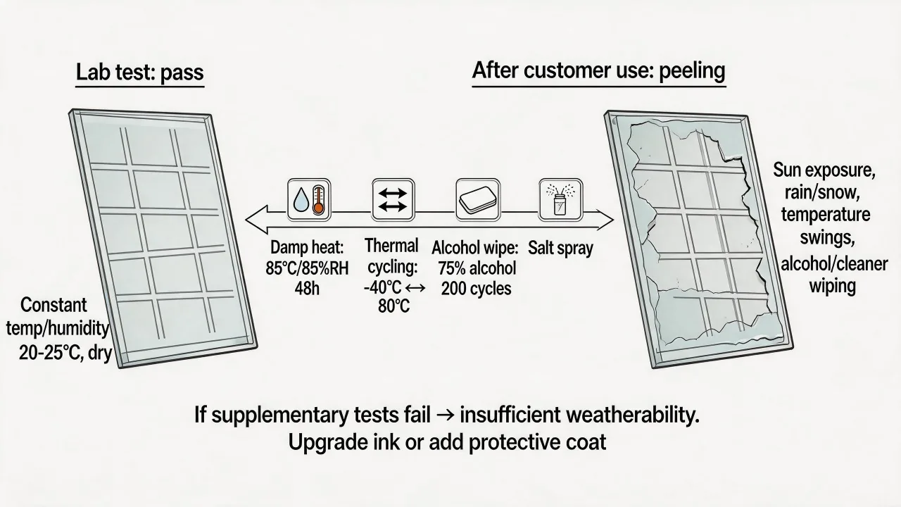
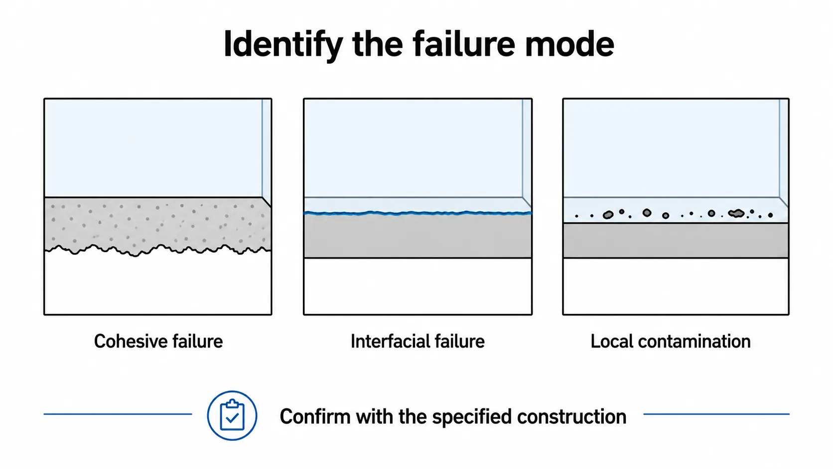
A cross-cut rating is one observation under one method. Field peeling after a pass can result from incomplete cure, contamination, underfiring, moisture, chemical exposure, thermal cycling, mechanical stress, aging or variation that the tested sample did not capture. Review the failure surface to identify whether separation occurred at glass–ink, within the film or between layers.
Adhesion should be evaluated using a mutually agreed test method, including the applicable standard, cut spacing, tape specification, conditioning period and acceptance rating. Record coating thickness where the method requires it, and recognize that tape tests do not provide an absolute bond-strength value.
ASTM D3359 is primarily scoped to relatively ductile coatings on metallic substrates and states limitations for non-metallic use. If parties adopt it for printed glass, document that agreement and its limitations. Add chemical, abrasion, thermal or environmental tests that represent service.
| Evidence | Question answered |
|---|---|
| Failure-surface microscopy | Where did separation occur? |
| Cure/firing record | Did the part receive the qualified process? |
| Cleaning and handling record | Was an adhesion-disrupting contaminant plausible? |
| Retain sample and aged sample | Is failure lot-specific or exposure-dependent? |
| Thickness/deposit map | Did excessive or insufficient film contribute? |
| Service simulation | Can the customer failure sequence be reproduced? |
For method selection and scope limitations, see Adhesion: Name the method and its limits →
Trace fogging, color bands and bubbles through the furnace
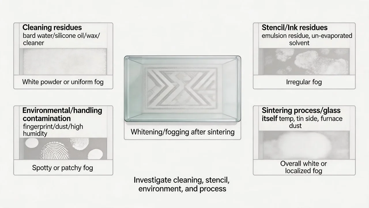
A white or fogged appearance after firing can be caused by residues, surface reaction, incomplete burnout, crystallization, moisture or optical scattering from a changed surface. Review glass cleaning, ink condition, drying and profile. Identify whether haze is on top of the print, within it or viewed through the glass.
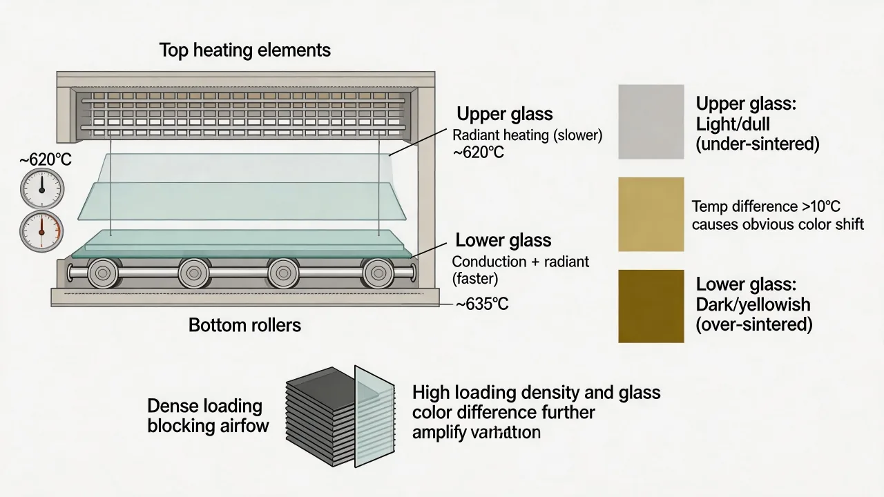
Color difference between upper and lower sheets or across furnace width may track loading, position, time–temperature history, deposit or glass construction. Map parts to furnace positions and compare measured profiles. Do not assign a universal ΔE to a temperature difference; establish the relationship for the selected enamel and product.
To reduce firing bubbles, control mixing and rest/deaeration per supplier guidance, avoid excessive shear, keep the screen clean, prevent overly heavy deposit and provide appropriate drying before firing. Confirm that the thermal profile allows vehicle removal and enamel maturation. A second pass may worsen gas entrapment.
Rework and scrap decisions are product-specific
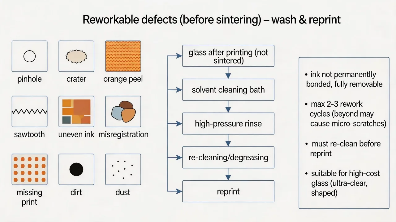
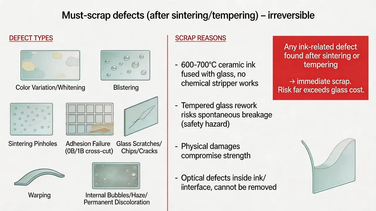
A defect does not automatically require immediate scrap, and apparent washability does not automatically authorize rework. Before cure, some organic inks may be removable with an approved method. After full cure or ceramic firing, removal may be difficult, unsafe for the glass surface or incompatible with product requirements. Even when stripping is possible, scratches, residues and altered surface condition must be considered.
Create a disposition matrix for each product and process stage. Define which defects may be cleaned, reprinted, refired, used-as-is by concession or scrapped; name who can approve each route. Medical, safety, architectural and food-contact products may have stricter traceability or rework restrictions.
Validate the reworked part through the same critical tests as normal production, plus checks for risks introduced by rework. Keep the original nonconformance and rework history linked to the lot. The goal is not maximum salvage; it is a controlled decision supported by evidence.
Standards referenced
Check the current edition and scope before writing a customer specification. Links below point to the issuing organizations.
Contact Us
Your feedback fuels our growth, and your questions drive our solutions.
We value your feedback, inquiries, and suggestions. Please feel free to get in touch with us
General inquiries
Please contact us via sales@bo-glass.com, and we will reply to you as soon as possible.
Interested to work with us
Drop your resume at info@bo-glass.com
and we will get back to you shortly.
We uses the contact information you provide to us to contact you about our relevent content, products, and services.