
Annealing, Cooling and Quality Inspection of Lampworked Borosilicate Glass
Annealing and inspection connect lampworking with the requirements of the finished component. Correct external shape alone does not establish acceptable residual stress, wall thickness, joint integrity or service performance. A reliable release decision combines evidence from the thermal cycle, drawing inspection and the functional tests relevant to the application.
Control sequence: define acceptance → qualify the kiln and load → control the complete cycle → inspect under specified conditions → review finishing and deviations → release traceable components.
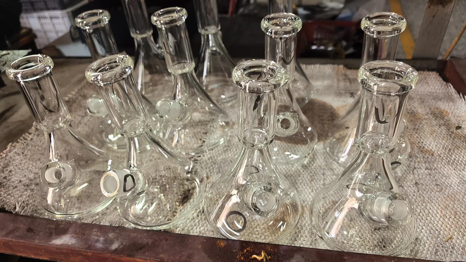
Define the Annealing and Release Requirements
Local heating and uneven cooling during fabrication can leave residual stress. Annealing provides conditions for stress relaxation, followed by controlled cooling to limit the stress remaining in the finished part. Heating used to manage work during fabrication should be distinguished from the final annealing treatment.[1]
Specify an agreed residual-stress or birefringence requirement and a suitable inspection method. An undefined claim of completely “stress-free” glass gives neither production nor inspection a usable acceptance limit.
Annealing is distinct from thermal tempering and chemical strengthening. It does not repair cracks, incomplete fusion, thin sections or incompatible glass combinations, and does not establish a pressure rating or service life.
Connect the forming history, kiln cycle and delivered condition. The lampworking process control guide covers the forming, joining and interruption records that should accompany each component into this stage. Record additional heating and subsequent finishing. A warm holding stage is not automatically the final annealing cycle. Plan release checks after the last operation capable of changing the characteristic being accepted.
Use Glass-Specific Thermal Reference Data
Start with supplier data for the identified glass grade and review every constituent in a joined assembly.
Swipe horizontally to view all columns.
| Reference value | Meaning for process development |
|---|---|
| Annealing point | A reference associated with relatively rapid stress relaxation under specified conditions |
| Strain point | A lower reference at which stress relaxation is much slower |
| Transformation temperature, Tg | A measured glass-transition characteristic with a different definition from the annealing point |
| Softening point | A deformation reference under a specified test method, rather than an annealing setpoint |
For example, Corning lists an annealing point of 560°C and a strain point of 510°C for Code 7740. These are reference values for that grade, not a complete programme for all borosilicate components.[2]
The production cycle must also establish entry conditions, heating, equalisation, holding, cooling and loading limits. Use consistent definitions and units. A maximum service temperature, softening temperature or another grade's data cannot simply replace the selected material's annealing information.
Verify the Kiln and Temperature Measurement
Select a kiln for the usable volume, load and control needed by the process. Chamber size and maximum temperature are only part of that assessment.
Keep three activities distinct. Calibration assesses the temperature measurement chain. Uniformity assessment determines temperature differences within the working space. Process verification demonstrates that the selected programme and loading arrangement produce acceptable components.
A manufacturer's uniformity specification may describe an empty working space at a stable hold. That condition does not establish uniformity throughout a loaded heating and cooling cycle. Check the stated working volume, measurement accuracy and test conditions.[3]
The controller setpoint, sensor reading and temperature within the glass are different quantities. Thick joints, shielded regions and fixture contacts can respond differently from the control sensor.
During development, use suitable additional sensors, representative instrumented parts or another justified method to understand the relationship between recorded conditions and the load. Establish the permitted programme, loading patterns and positions from that evidence.
Retain the actual temperature history and significant overshoot, power interruptions or departures from the programme. Define the checks needed after changes to the measurement chain, kiln configuration or loading arrangement that could affect the demonstrated result.
Plan Loading for Thick Sections and Complex Assemblies
Identify the most demanding finished sections before choosing the cycle. Nominal starting-tube wall thickness may overlook material gathered at closures, flange roots, tube joints, branch connections and solid attachments.
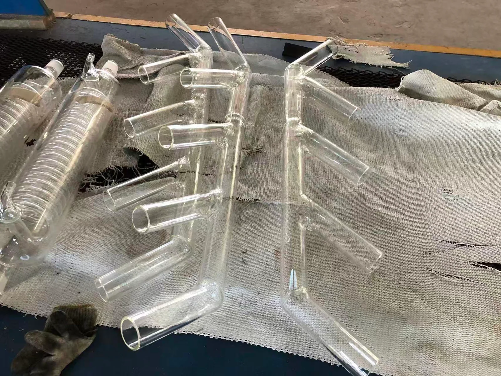
Consider maximum local section, abrupt thickness transitions, partly enclosed regions, heavy additions on thin walls and uneven exposure within the load. A cycle demonstrated on straight tubing does not automatically cover a complex assembly made from the same tube size.
Specify orientation, spacing, permitted positions, shelves and supports. Support long branches and heavy features without forcing the component into shape or unnecessarily restraining expansion and contraction. Contact materials must suit the thermal conditions and protect the agreed surface quality. Identify acceptable contact locations on visible or functional areas.
Include the range of loading conditions that production will use. Fixtures, closely spaced components and mixed geometries can change heat transfer; repeated batches need a reproducible arrangement.
For joined clear and coloured glasses, matching nominal expansion values do not resolve every compatibility question. Annealing response and colour development may differ. Persistent stress near a connection should trigger review of material compatibility, section geometry and restraint alongside the programme. Extending the cycle cannot be assumed to correct an unsuitable material combination.
Control the Cycle from Kiln Entry to Inspection Readiness
Treat entry, holding, cooling and unloading as one qualified sequence. Hot entry and reheating after cooling are different starting conditions and need appropriate routes.
Swipe horizontally to view all columns.
| Stage | Control objective | Condition to establish |
|---|---|---|
| Entry and heating or recovery | Bring the load towards treatment without damage | Permitted entry condition, loading sequence and heating behaviour |
| Equalisation and soak | Treat the relevant glass sections sufficiently | Relationship between load temperature, recorded conditions and holding time |
| Cooling through the annealing range | Limit residual stress developed during cooling | Verified cooling stages and acceptable final stress results |
| Lower-temperature cooling and unloading | Manage thermal differences and handling | Demonstrated cooling and unloading criteria for the component |
| Inspection readiness | Obtain results representing the specified condition | Required thermal stability and measurement environment |
Account for loading time and the complete section
If parts enter a heated kiln throughout production, account for door openings and individual entry times. The final treatment must cover the entire load, including the last component added.
Define when the soak begins: for example, after specified sensor conditions and an equalisation period established during development. Reaching the controller setpoint does not establish that a thick joint has received the required treatment. Time spent holding earlier parts cannot automatically be credited to a newly loaded assembly.
Verify actual cooling behaviour
Establish rates and transition conditions for the relevant stages, then compare the programme with the actual furnace response. A longer soak does not automatically compensate for unsuitable cooling.
Below the strain point, stress relaxation becomes very slow, but temperature differences can still generate temporary stresses sufficient to cause thermal breakage. Continue controlling cooldown according to the demonstrated section, geometry and loading conditions.
Separate unloading from measurement
Use an unloading criterion appropriate to the load, rather than a universal door-opening temperature. Check for sticking or restraint before removing supports. Handle through designated areas, prevent glass-to-glass impact and avoid abrupt contact with substantially colder surfaces.
Maintain identification and allow parts to reach the specified inspection condition. Being cool enough to handle does not necessarily mean being ready for final dimensional or stress measurement. Record temperature where it materially affects the result.
Choose Qualification Tests and Routine Inspections
Qualification establishes whether the design and manufacturing route meet requirements under the conditions evaluated. Routine inspection checks the selected characteristics needed to control ongoing supply. Destructive tests may belong in qualification or periodic verification rather than inspection of every delivered part.
Select applicable checks from the component's function and consequence of failure. A decorative cover and a vacuum assembly will not necessarily need the same tests. The following table organises the evidence; it is not a requirement to perform every item on every product.
Swipe horizontally to view all columns.
| Evidence | Conditions to define | Acceptance basis |
|---|---|---|
| Annealing record | Programme, actual history, loading and deviations | Demonstrated process conditions |
| Residual stress or birefringence | Method, orientation, location, optical path and units | Agreed screening or quantitative limits |
| Dimensions, wall and bore | Datums, support, temperature and local measurement capability | Drawing and passage requirements |
| Surfaces and joints | Viewing conditions, evaluated zones and defect definitions | Written limits and controlled references |
| Leak tightness | Medium, pressure difference, temperature, duration and detection capability | Specified leakage limit |
| Service performance | Relevant pressure, vacuum, thermal, mechanical or optical conditions | Application-specific test criteria |
| Final condition | Finishing stage, cleanliness and post-test checks | Agreed delivery requirements |
Specify method, sampling, frequency and acceptance decision for each selected characteristic. Include relevant load positions and difficult sections during qualification. Establish what happens to tested components: release, additional inspection, retention or disposal. A routine check should have a demonstrated relationship to the characteristic it controls.
Inspect Residual Stress and Birefringence
Polarised-light inspection assesses stress-related optical effects in transmitting glass. Select the instrument configuration and method to match the required result, material and geometry.
Distinguish screening from measurement
A polariscope can reveal stress patterns. Quantitative optical-retardation measurement requires an appropriate configuration, calibration and procedure; instrument suppliers distinguish qualitative from quantitative systems.[4]
For screening, define the viewing arrangement, orientations, regions and reference images. A dark appearance at one angle does not establish zero stress: stressed regions can appear dark because of their orientation relative to the polarising elements. Evaluate the views required by the method rather than selecting the least visible pattern.
For quantitative work, identify the instrument, settings, calibration status, measurement positions and reporting convention. Photographs document a specified observation, but image brightness or colour alone should not be treated as a calibrated stress value.
State the quantity and optical path
Distinguish retardation in nm, retardation normalised by glass path length in nm/cm, and calculated stress in MPa. They are different quantities. Report the actual quantity measured and the method used for any conversion.
Calculation of stress needs the relevant stress-optical coefficient and a justified treatment of the optical path and stress state. Do not convert a displayed retardation value using nominal wall thickness without establishing that this represents the evaluated path.
Where an observation combines several regions along the viewing path, document that limitation rather than reporting it as an isolated local stress value.
Address curved walls and limited transmission
A view through both tube walls differs from a simple flat specimen. Curvature, overlapping surfaces, thick joints and varying path length can complicate interpretation. Record viewing direction and support conditions, and identify regions that cannot be assessed reliably.
Specialised accessories, such as suitable immersion arrangements, can reduce the lensing effect of curved surfaces. Their use requires a procedure appropriate to the part; the availability of an instrument configured for a particular standard does not make that standard applicable to every product.[5]
Strong colour, opacity or absorption can prevent useful transmitted-light assessment. Agree an alternative verification approach during development, with its coverage and limitations recorded. Stress inspection supplies evidence about the evaluated optical characteristic; it does not replace crack, joint or functional inspection.
Check Dimensions, Surfaces and Joint Integrity
Verify functional geometry
Use the finished drawing and its datums to assess length, diameters, bends, branch positions, openings, flanges and sealing-face relationships. Measure wall thickness and internal passage where forming may create local thinning or restriction; an acceptable external profile cannot establish either.
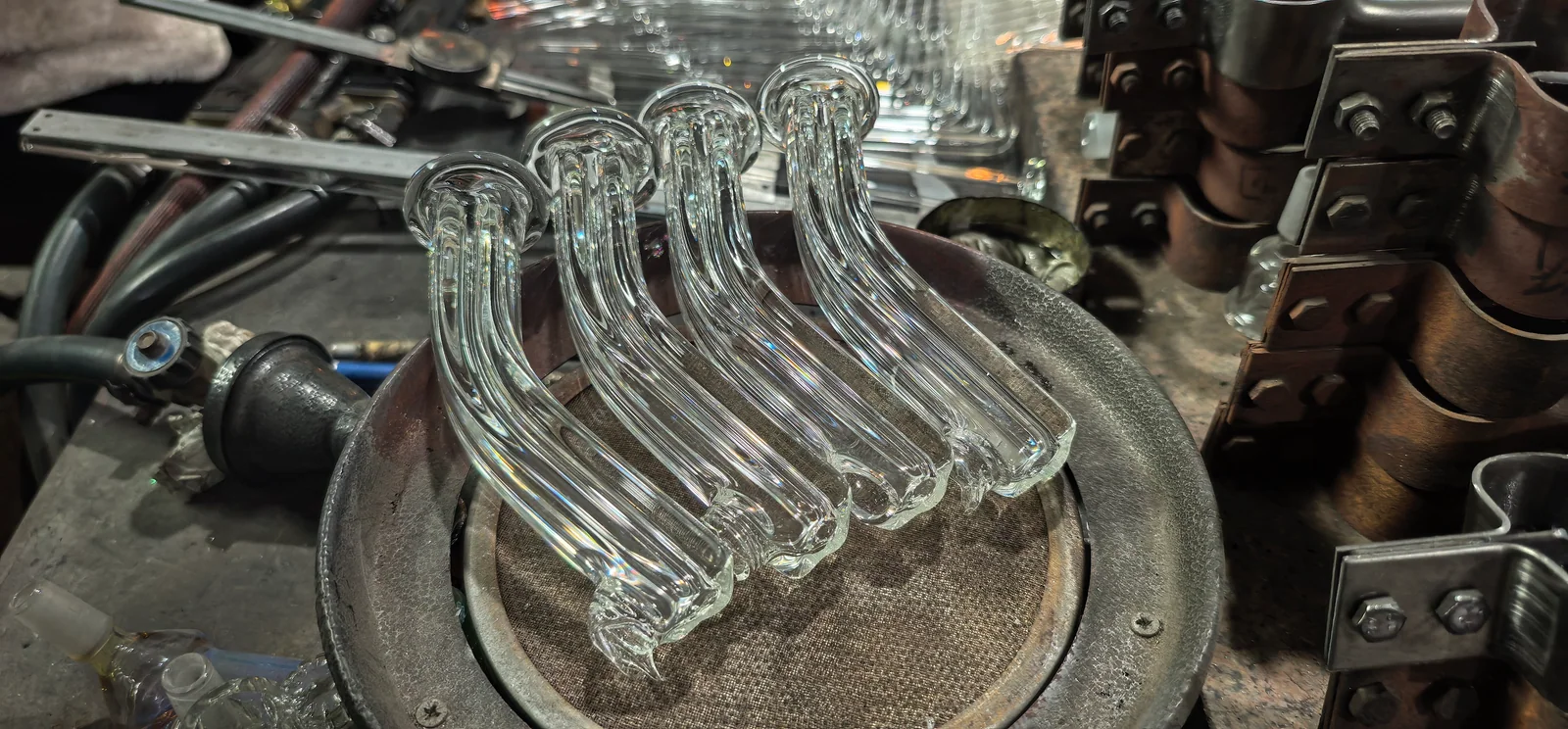
Define positions around and along the part, support arrangement and suitable measurement contact. Development samples may require sectioning or another appropriate method for inaccessible geometry. Establish how those findings support routine checks.
Use controlled mating parts or gauges for assembly fit where appropriate. Do not force a part into a fixture to obtain an acceptable result. If the design specifies a constrained installed condition, distinguish it from free-state geometry.
Apply location-specific defect limits
Specify lighting, background, distance, orientation and magnification where relevant. Examine cracks, checks, chips, scratches, tool marks, bubbles, inclusions, haze, deposits and internal contamination under the agreed conditions.
At joints, assess the accessible circumference, fusion condition, passage and transition into adjacent sections. A smooth exterior does not confirm internal continuity.
Define acceptance by defect type and location as well as size. A decorative surface, sealing face and loaded connection may need different criteria. Reference samples and photographs can clarify appearance boundaries, but a cosmetic allowance must not be used to approve cracks or structural defects.
Verify Leak Tightness and Service Performance
Define the test boundary and result
A leak test measures leakage under specified conditions. Structural pressure or vacuum testing evaluates behaviour under a defined pressure difference and support arrangement. Passing one does not establish the other.
For leakage, specify the medium or tracer, internal and external pressure conditions, absolute or gauge reference, temperature, stabilisation, duration, method, detection capability and reporting units. Identify the connections included in the test boundary and distinguish component leakage from temporary seals or fixtures.
Pressure-change methods need thermal stability: changing temperature can influence the reading. A result with one medium or condition should not be translated to service performance without a justified relationship.
Match loading to the application
Pressure and vacuum tests require components designed for the intended conditions and an appropriate protected test arrangement. Establish pressure difference, temperature, application rate, hold period, fixtures and acceptance criteria. Positive internal pressure and external pressure under vacuum impose different loading; evidence for one is not proof of suitability for the other. There is no universal proof-pressure multiplier for lampworked glass.
For thermal qualification, specify starting temperature, exposure medium, timing, transfer and cycles, including mounting and surface condition. A temperature difference alone does not define a thermal-shock test. Include relevant cleaning or sterilisation conditions where they are part of service.
For mechanical performance, define load location, direction, application and support. For optical performance, specify wavelengths, measurement geometry, glass path and the relevant illuminated or viewing condition. Raw-material transmission data do not represent a measurement of a finished curved part.
Define checks after exposure, such as cracks, leakage, dimensional change, joint condition or optical change. Record whether the tested parts remain suitable for delivery under the agreed plan.
Reinspect After Finishing and Rework
Cutting, grinding, lapping and drilling can change previously accepted dimensions, edges, surfaces and local sections. Repeat checks affected by the actual operation, including remaining wall or flange thickness, sealing-face geometry, cleanliness and relevant functional results.
Cold finishing does not automatically require another annealing cycle. Assess the operation, observed condition and product requirements. Additional annealing should not be used to conceal unresolved machining damage.
Flame polishing, hot repair or further joining adds thermal exposure. Review the revised route for annealing and subsequent stress, dimensional, surface and functional checks before release. A repaired feature can also affect neighbouring regions.
For coatings, decoration or other treatments, verify the delivered appearance and interfaces, and assess compatibility with any subsequent heating. Keep the rework instruction and results linked to the affected parts. Previously accepted records remain useful history, but release must reflect the final delivered condition.
Control Sampling, Deviations and Final Release
Define the lot and inspection extent
Preserve the relationship between material lots, forming conditions, annealing batches and finished components. Define the inspection lot and sampling rule so a failure can be traced to the affected population.
Acceptance sampling supports a lot decision under the selected plan; it does not demonstrate that every untested item individually passed. State required individual inspection explicitly. Choose the inspection extent with regard to failure consequences and the method's ability to detect the relevant condition.
Make reliable acceptance decisions
Display resolution alone does not establish measurement capability. Consider calibration, repeatability, positioning and method uncertainty. Agree how borderline results will be judged before production. Retesting should follow an established procedure, with all relevant results retained; repeated measurement and selective reporting must not be used to obtain a pass.
If a cycle deviation or inspection failure occurs, identify and segregate the affected parts. Review the cause and supporting evidence before choosing additional inspection, reannealing, repair or rejection. Define the checks needed to justify any proposed recovery. Persistent failures need investigation rather than repeated cycles without a demonstrated corrective purpose.
Release the documented final condition
Confirm completion of applicable inspections, closure of deviations and the disposition of tested or reworked items. Connect the drawing revision, glass identity, annealing record and final results in the release record. Preserve identification during packing so accepted parts remain traceable to that evidence.
For a manufacturing and inspection quotation, provide BO-Glass with the drawing, glass requirements, service conditions, critical interfaces, applicable stress or performance criteria and expected quantities.
References
- Joe Walas / ILPI, The Scientific Glassblowing Learning Center — Glass Strain and Annealing.
- Corning — Code 7740 Glass Technical Data, including annealing and strain points.
- Nabertherm — Temperature Uniformity.
- Strainoptics — Instruments.
- Strainoptics — PS-100-E671 Polarimeter Bulletin.
Contact Us
Your feedback fuels our growth, and your questions drive our solutions.
We value your feedback, inquiries, and suggestions. Please feel free to get in touch with us
General inquiries
Please contact us via sales@bo-glass.com, and we will reply to you as soon as possible.
Interested to work with us
Drop your resume at info@bo-glass.com
and we will get back to you shortly.
We uses the contact information you provide to us to contact you about our relevent content, products, and services.