
BO-GLASS / TECHNICAL MATERIALS
Optical Transmission, Thickness and Color of Soda-Lime Glass
A clear cover, a colored lens and a frosted shade can all transmit light while performing different jobs. Selecting soda-lime glass means deciding how much light should pass, which wavelengths matter, how the light should be distributed and what the finished component should look like.
This guide explains how composition, thickness, shape and finish affect those decisions. It also shows how to turn an optical requirement into a specification for a custom glass component. For composition, forming routes and general material selection, see our soda-lime glass overview.
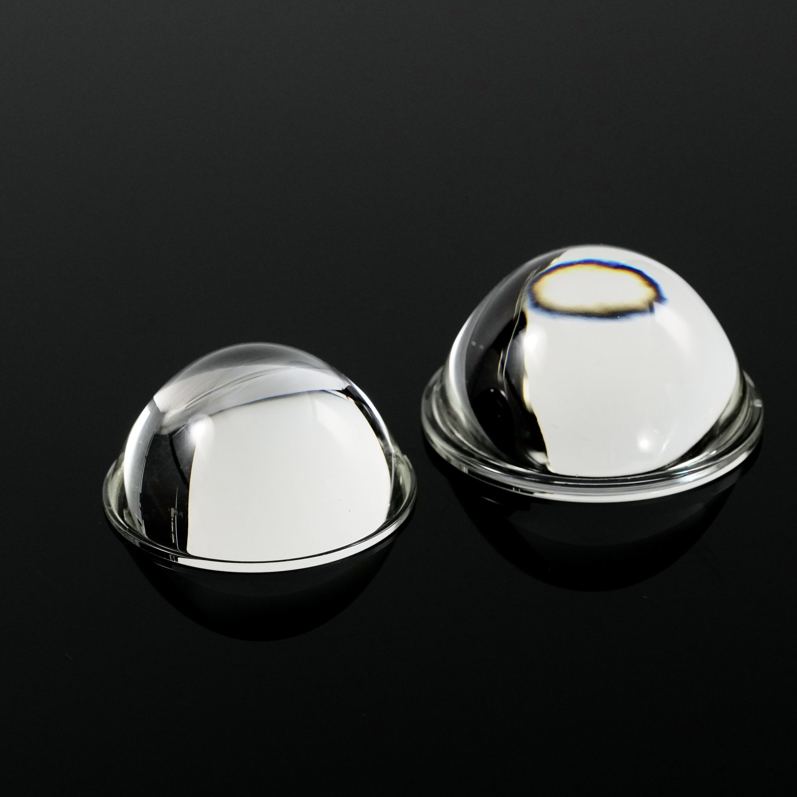
Start With the Optical Function
Define the result before requesting a transmission percentage.
| Intended function | What needs to be decided |
|---|---|
| Clear viewing through a cover | Light transmission, image distortion and the viewing area, distance and angle. |
| A visually neutral glass component | Acceptable color through the body and at exposed edges, under defined viewing conditions. |
| A diffuser that masks LEDs | Source visibility, surface brightness variation and useful light output in the actual assembly. |
| A colored lighting element | Transmitted color, unlit appearance and compatibility with the intended source spectrum. |
| A window for an optical sensor | Transmission across the sensor’s operating band, incidence angles and acceptable beam deviation. |
A high transmission value alone does not establish clear imaging, even illumination or accurate color. Identify the source, observer or detector and the functional region of the glass before choosing the measurement.
What Happens When Light Passes Through Glass?
Three effects deserve separate attention:
- Reflection: some light returns from an interface between materials, such as air and glass.
- Absorption: some light is absorbed within the glass or a coating; the amount depends on wavelength and material.
- Scattering and refraction: light changes direction because of surface texture, internal structure or component geometry. It may leave the receiving area without having been absorbed.
Play animationClose animationDirect and diffuse transmission
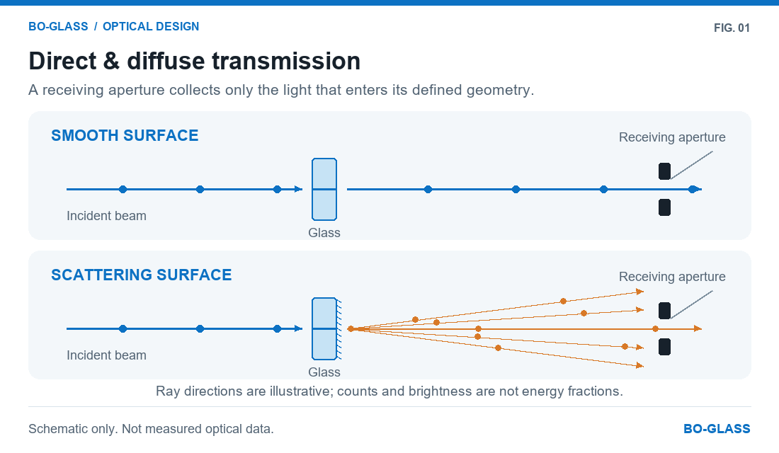
This distinction matters when troubleshooting a low reading. A frosted or curved part can redirect light away from a narrow detector. That reading alone does not reveal how much energy the glass absorbed.
Why clear glass still reflects light
Pilkington’s ATS-129, September 2026 lists a refractive index of 1.523 at 589.3 nm for soda-lime-silica float glass.
For a smooth, uncoated air/glass interface at normal incidence, a simple Fresnel calculation gives:
R = [(n − 1) / (n + 1)]²
R = [(1.523 − 1) / (1.523 + 1)]² ≈ 0.043, or approximately 4.3%.
Here, air is approximated as having a refractive index of 1 and the interface is treated using a non-absorbing optical model. This is a calculated single-interface reflectance, not a measured transmission value for a finished cover. The underlying interface equations are described in NIST’s regular spectral-transmittance publication, Appendix A.
Low-iron composition can reduce material coloration and absorption, but it does not remove air/glass reflection. Surface reflection, bulk absorption and diffusion are separate design questions.
How Thickness and Curvature Affect Transmission
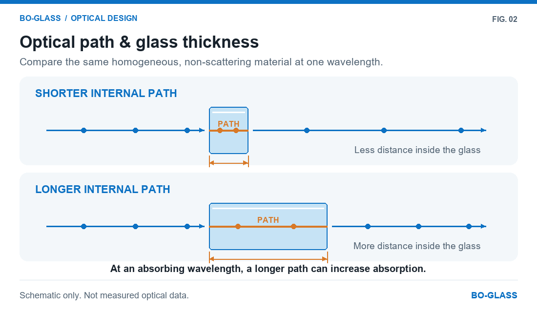
At a wavelength where the material absorbs light, a longer path through the same homogeneous glass generally increases absorption. A thick rim can therefore differ in transmitted color or brightness from a thinner body.
For a curved part, nominal wall thickness does not describe every light path. Ray direction and the local surface angles affect the distance traveled inside the glass and the direction in which light emerges. Changes in wall profile or surface form can also affect image distortion.
Play animationClose animationThickness and internal optical path
A published float-glass comparison
Pilkington’s July 2017 North American Architectural Glass Product Guide provides the following visible-light transmission values in its uncoated monolithic glass table:
| Nominal thickness | Pilkington Optifloat™ Clear | Pilkington Optiwhite™ low-iron glass |
|---|---|---|
| 6 mm | 88% | 91% |
| 10 mm | 86% | 91% |
The guide describes normal-incidence optical data, a visible band of 380–780 nm and calculations from laboratory spectral measurements using LBNL Window 6.3. The values above are rounded, typical production references from that edition. Pilkington product guide, printed pages 41 and 51.
This comparison illustrates the combined influence of material and thickness. The equal rounded low-iron values do not prove that thickness has no effect. These are published float-sheet examples, not BO-GLASS blown or pressed component specifications.
Estimating a change in optical path
For the same homogeneous, non-scattering material at a fixed wavelength, internal transmittance can be related to path length:
τᵢ(d₂) = [τᵢ(d₁)]^(d₂/d₁)
Internal transmittance excludes interface reflection. SCHOTT TIE-35 explains this distinction and the thickness relationship.
Illustrative calculation: suppose a hypothetical material has an internal transmittance of 0.98 over a 2 mm path at one wavelength. At 4 mm, the estimate is:
0.98² = 0.9604, or approximately 96% internal transmittance.
This is an arithmetic example, not product data. It does not include surface losses, coatings, scattering or the geometry of a complete cover. Do not apply the power rule directly to a finished diffuser’s transmission percentage or to a wavelength-weighted luminous-transmittance value.
Standard Clear, Low-Iron and Colored Glass
Standard clear glass
“Clear” describes a transparent appearance; it does not mean that every wavelength passes equally or that the material is completely colorless. Green coloration can become more apparent when viewing a longer path through the glass, including an exposed edge or thick section.
Judge the relevant body and edge appearance on a representative wall profile. A thin flat sample may understate the visible tint of a thick formed feature.
Low-iron glass
Low-iron grades reduce the coloration associated with iron-related absorption. Pilkington Optiwhite™ is a documented float-glass example developed for high transmission and a more neutral appearance.
For a custom blown or pressed part, establish the actual composition and available manufacturing route. A low-iron sheet-glass datasheet does not establish the properties of another melt formulation. Low iron also does not, by itself, specify optical homogeneity, surface accuracy or imaging quality.
Body-colored glass and surface coloration
Body coloration and a colored coating are different constructions. A body-colored glass can show changes with optical path length; a surface treatment introduces its own coverage, thickness and durability requirements.
Specify both unlit appearance and transmitted color where they matter. A color approved against a white background may behave differently when illuminated by the intended LED. Include cleaning, handling and operating conditions when selecting a surface treatment.
For components exposed to heating and cooling, review the thermal expansion and thermal-shock requirements alongside the optical specification.
Transmission, Haze and Clarity Are Different Quantities
| Quantity | What it describes | Conditions to retain with the result |
|---|---|---|
| Spectral transmittance | Transmission as a function of wavelength. | Wavelength range, resolution, incidence and collection geometry. |
| Regular or direct transmittance | Light within a defined receiving beam. | Alignment, receiving aperture and incidence angle. |
| Total transmittance | Collected direct and diffusely transmitted light. | Collection arrangement and measurement method. |
| Luminous transmittance | Transmission weighted for an illuminant and visual response. | Illuminant, weighting convention and method. |
| Haze | The method-defined share of total transmitted light scattered outside a specified angular range. | Method, specimen suitability and measurement conditions. |
| Clarity | The effect of narrow-angle scattering on detail visibility. | Method and viewing task. |
BYK’s transparency measurement guidance distinguishes transmission, haze and clarity; JASCO explains the effect of transmission collection geometry. These distinctions explain why a specimen can transmit substantial light yet obscure objects behind it.
Haze is not a complete diffuser-performance specification. It does not independently establish LED masking, surface uniformity, beam distribution or luminaire glare performance. Two diffusers with similar haze can still perform differently in the same enclosure.
For a curved or strongly scattering component, confirm that the proposed instrument and procedure suit the specimen before making a haze value an acceptance criterion.
Choosing a Smooth Surface, Frosting or a Diffusing Composition
Different optical effects require different material or surface choices:
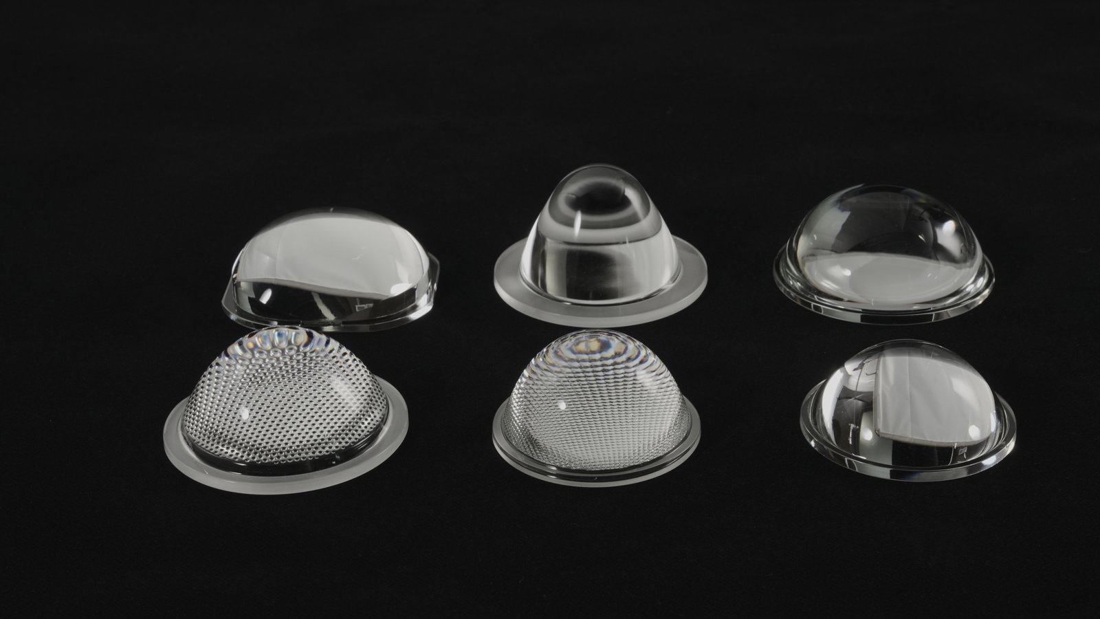
- Smooth transparent surfaces suit clear viewing and applications where uncontrolled scattering is undesirable. Review shape and distortion as well as transmission.
- Frosted or sandblasted surfaces redistribute light through surface scattering. Evaluate which side is treated, the coverage, source visibility and the resulting light output. A matte appearance alone does not establish an anti-reflection function.
- Pressed patterns and prismatic features redirect light through their geometry. Their effect depends on feature shape, orientation and the source position; they should not be treated as interchangeable with random frosting.
- Opal or milk-white compositions can provide scattering within the glass body. Their optical behavior must be reviewed for the actual formulation and wall profile, rather than assumed from a white appearance.
Greater source masking can involve a tradeoff with useful output or distribution. Select the material and finish together, then evaluate the intended assembly. Changing texture, coating or treated area can require a new optical approval even when the nominal glass dimensions remain unchanged.
Why the Light Source Changes Color and Apparent Brightness
The transmitted spectrum depends on both the incoming source spectrum and the glass’s wavelength-dependent transmission. A component that looks acceptable under one source can produce a different result under another.
Luminous transmittance is therefore not a simple unweighted average of several wavelength readings. The illuminant and visual weighting are part of the quantity, as illustrated in NIST’s transmittance guidance, Appendix A. A standardized broadband value should not automatically be treated as the transmitted-output fraction for every LED or sensor.
For appearance approval, distinguish:
- Transmitted color with the source operating.
- Reflected or unlit color under the agreed illumination and background.
- Variation across the component and between approved samples.
Keep the source, drive condition, source-to-glass position and relevant enclosure surfaces consistent during comparison. Identify the reference sample and viewing arrangement. Photographs can communicate intent, but exposure, white balance and display settings make them insufficient as the sole color acceptance standard.
Visible clarity does not establish UV or infrared performance. For a spectral function, identify the wavelength band and obtain appropriate data for the actual material and finish.
Measuring Flat Samples and Curved Components
A flat coupon can help compare materials or monitor a finishing process. Its result represents the complete component only when that relationship has been established.
A curved wall can move the transmitted beam away from a detector, while a diffuser sends light over a wider range of directions. JASCO’s integrating-sphere guidance discusses optical-path changes in non-planar, thick and scattering specimens. Shimadzu also explains that a typical scatter-transmission sphere collects transmitted and forward-scattered light, rather than automatically collecting backward-scattered light.
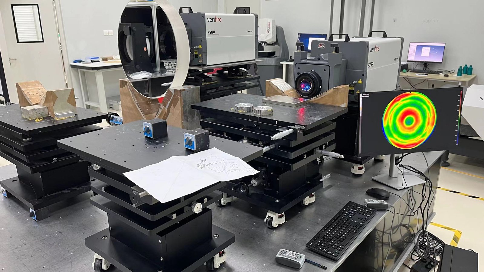
Agree these details before comparing readings:
- Specimen: complete component, cut section or separately produced coupon; identify the material and final finish.
- Optical zones: mark the viewing or emitting area, rim and hidden mounting surfaces on the drawing.
- Position and direction: define measurement locations, local orientation and relevant thickness.
- Collection: choose the beam, aperture and collection arrangement for the quantity required; avoid beam clipping and stray light.
- Preparation and fixture: define cleaning, handling and repeatable positioning without obstructing the optical path.
- Report: retain specimen identity, method, settings, results and departures from the agreed procedure.
Where production checks use a coupon, correlate it with representative finished parts during qualification. Where the function is determined by the assembled lamp, include an assembly-level comparison.
For full luminaire beam design and glare control, use our separate lighting-glass optical design guide.
Example: Specifying a Frosted Lighting Cover
Consider a proposed frosted cover intended to conceal individual LEDs while retaining useful output. This is an illustrative specification framework, not a customer case or an available product rating.
| Requirement | What the project specification should record |
|---|---|
| Controlled documents | Drawing revision, material identification and a separate finishing specification. |
| Functional zones | Areas where transmission, source masking or appearance criteria apply; distinguish hidden seating surfaces. |
| Transmission | Required spectral band or luminous quantity, limit, specimen and collection method. |
| Diffusion | Source-visibility or surface-uniformity criteria in the defined LED fixture; include output requirements where relevant. |
| Color | Transmitted and unlit criteria, reference, illuminant or source, viewing conditions and any numerical limits. |
| Finish coverage | Treated side, boundary of treatment and areas to remain untreated. |
| Sampling | Qualification specimens, routine checks and the agreed batch decision process. |
| Records | Identified samples, measurement configuration, approved reference and acceptance revision. |
Resolve missing limits before production. “High transmission,” “high haze” or “match the photo” leaves important parts of the requirement undefined.
When a trial cover hides the LEDs but produces insufficient useful output, review scattering, source spacing and enclosure losses together. When a thick rim looks greener, compare its material and optical path before changing a finish that serves another purpose.
Questions About Soda-Lime Glass Optical Performance
Is low-iron glass always the right choice?
Use it when reduced color cast or material absorption matters to the application. It does not replace a diffusion requirement, correct an unsuitable shape or eliminate surface reflection. Confirm the actual formed composition and representative thickness.
Does a higher haze value mean a more uniform lamp?
Not necessarily. Haze does not describe the complete angular output or the source-to-glass geometry. Evaluate source visibility and brightness variation in the defined assembly, alongside the required output.
Can a flat test coupon qualify a curved cover?
It can serve as a production surrogate only after its relationship to the finished component has been established. Otherwise, the curved part’s geometry and finish can produce a different measured or functional result.
Can clear soda-lime glass be specified as a UV or infrared window?
Only on the basis of suitable spectral data and application requirements. “Clear” is a visible appearance description, not a guaranteed passband, rejection band or sensor-window specification.
Discuss Your Optical Requirements
Send the drawing, optical zones, intended source or wavelength band, wall profile, finish and target quantity. Include a reference sample or existing inspection specification where available.
Tell us which result matters most: clear viewing, neutral color, LED masking, controlled distribution or transmission within a particular spectral band. This gives the material and manufacturing review a practical starting point.
References
Sources checked on 16 November 2026. Published values apply to the materials, editions and measurement conditions identified by their suppliers.
- Pilkington — ATS-129, September 2026: soda-lime-silica float-glass refractive index.
- Pilkington — Architectural Glass Product Guide, July 2017: historical North American float-sheet optical examples, printed pages 41 and 51.
- Pilkington — Optiwhite™: low-iron float-glass characteristics.
- SCHOTT — TIE-35: Transmittance of Optical Glass: internal transmittance and thickness relationships; general principles, not a soda-lime component datasheet.
- BYK — Transparency Measurement: transmission, haze and clarity distinctions.
- NIST — Regular Spectral Transmittance, SP 250-69: interface optics, spectral measurement and luminous weighting.
- JASCO — Diffuse Reflectance and Integrating Spheres: collection geometry and specimen-related optical-path changes.
- Shimadzu — How Do Integrating Spheres Work?: transmitted, forward-scattered and backward-scattered light in measurement arrangements.
Contact Us
Discuss Your Custom Glass Project
Share your drawing, photos or dimensions, together with the intended use and target quantity. We will review your requirements and discuss the next steps.
Sales Enquiries
Email sales@bo-glass.com with your part description, intended use and target quantity.
Send Your Design
Use the form to upload a drawing or describe an existing part. Mark critical dimensions and tell us which surfaces or features matter most.
Request a Custom Glass Quote
Upload a drawing or share dimensions, quantity, intended use and finish. Include any heat, pressure or chemical exposure.
Your drawings remain confidential.
We use the contact details you provide to respond to your enquiry. See our Privacy Policy for more information.