
Molten Glass Blowing Defects and Troubleshooting
Effective troubleshooting connects an observed defect with evidence from the material, tooling and production sequence. This guide helps designers, engineers and purchasing teams describe the problem, narrow the investigation and assess whether a corrective action has improved the finished component without creating another failure.
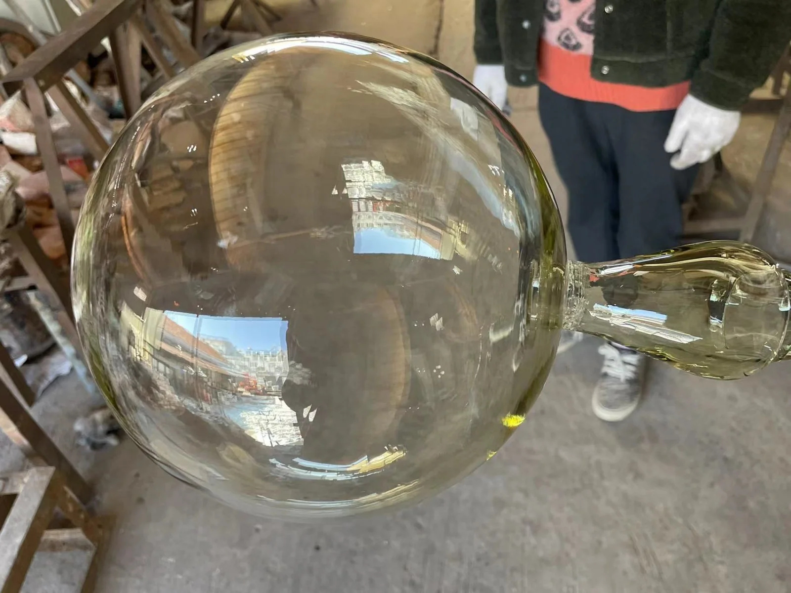
Quick-start: collect these five items
- The specification requirement and the observed departure, with location and scale.
- Failed samples and acceptable comparisons, identified by production stage.
- Material, melt, tooling and affected batch references.
- Forming, thermal, finishing and recent-change records.
- Containment status, investigation hypotheses and the proposed verification checks.
1. Define the Defect and Contain Affected Production
Describe the condition against a requirement. Replace “weak glass” or “bad surface” with its location, dimensions, frequency and effect on appearance, fit or function. State whether it is on a surface, within the glass or inside the hollow component.
Record when it was first detected, but keep that separate from its possible origin. Grinding can reveal an earlier flaw; assembly can load an already damaged edge. Detection provides a starting point, not a diagnosis.
Swipe horizontally to view all columns.
| Defect | Evidence | Review | Limit |
|---|---|---|---|
| Bubbles or inclusions | Location, population, melt comparisons | Inputs, melt, gathering | Appearance does not identify the source |
| Wall or shape variation | Thickness map, stage profiles | Preform, heat, movement, release | Weight does not prove distribution |
| Repeated surface marks | Position against tooling | Contact, closure, preparation | Repetition does not prove cavity damage |
| Openings or internal features | Multiple views, interface checks | Transfer, finishing, handling | One view can conceal a feature |
| Cracks or breakage | Fragments, origin evidence, history | Thermal and mechanical exposure | Failure time is not origin time |
| Cloudiness or colour | Matched lighting and samples | Glass, surfaces, treatments | Similar appearances can have different causes |
Identify potentially affected production and keep its status separate from released stock. Retain failed and acceptable samples with photographs, a scale and batch references. Preserve fracture surfaces and contamination evidence before cleaning, polishing or reheating.
The customer defines acceptance requirements; the manufacturer investigates the route and validates changes. “Handmade” is not a substitute for agreed limits on bubbles, texture or marks.
2. Investigate Bubbles, Inclusions and Material Inhomogeneity
Gas and Solid Inclusions
Define bubble terminology before comparing reports. “Seed” commonly describes a small bubble and “blister” a larger one, but project limits need stated sizes, populations and locations. Distinguish enclosed bubbles from those opening onto a surface.
Compare representative material and melt samples with components from successive stages. Bubbles may pre-exist forming, become trapped between gathers or be revealed and stretched during expansion. Their final shape alone does not determine which mechanism occurred.
Swipe horizontally to view all columns.
| Pattern to compare | Evidence to obtain | Next investigation |
|---|---|---|
| Several products share one melt | Melt samples and production references | Inputs, preparation and shared downstream work |
| Defects concentrate near an addition | Layer or attachment sequence and samples | Added glass, contact and joining practice |
| Frequency changes after charging | Before/after samples and charge history | Input changes, recovery and forming conditions |
| Embedded solid particles recur | Microscopy and source-material comparisons | Cullet, refractory, tools or other contamination |
Describe solid inclusions by position, size, colour and relationship to cracks without naming their composition prematurely. Review input segregation, refractory work, glass-contact surfaces, pipe scale and deposits. Include air cleanliness where an assisted arrangement makes it relevant.
Microscopy, compositional examination or specialist bubble-gas analysis can help distinguish hypotheses. Gas identification can inform possible origins without guaranteeing a unique cause. Select the investigation for the decision required; a dark speck cannot be assigned a material identity from appearance alone.
Cords, Striae and Optical Distortion
Streaks can reflect material inhomogeneity, but a distorted view through hollow glass can also arise from curvature, thickness variation or surface waviness. Compare reflected and transmitted views under consistent conditions, then use specialist examination where the distinction remains unresolved.
For confirmed material-related features, examine composition consistency, mixing and glass-contact interactions. For a geometric effect, follow wall distribution and forming history. Verify the actual requirement, including illuminated appearance where applicable. After a bubble correction, check size, population, surface openings and local thickness, rather than count alone.
3. Diagnose Wall Distribution, Incomplete Inflation and Shape Drift
First establish the measurement pattern. Check location, support, orientation and stage so hot estimates are not compared directly with finished measurements. Map critical body sections, shoulders, necks, corners, heel, base and attachment regions as appropriate.
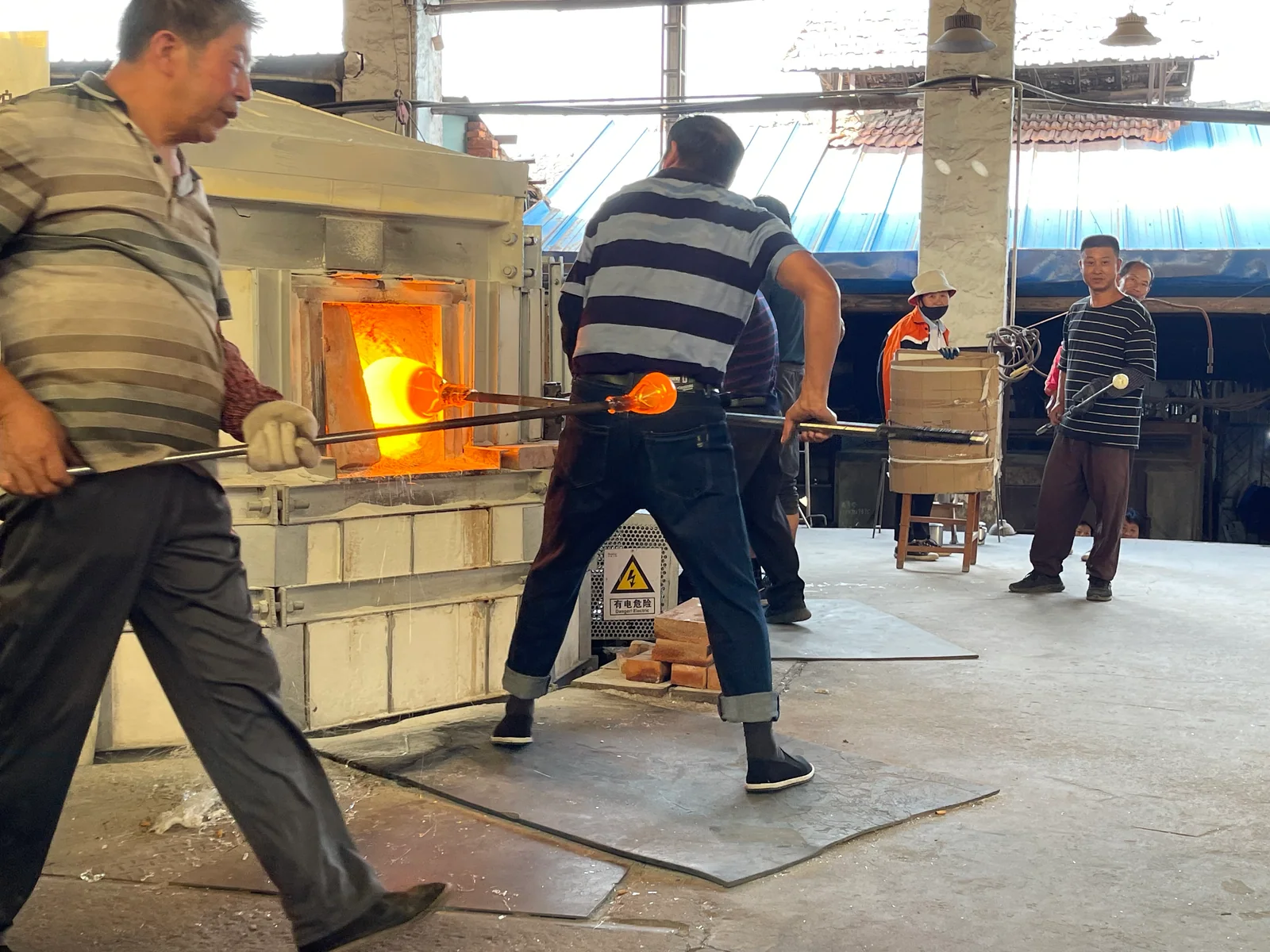
Equal weights do not establish equal wall distribution. An acceptable external profile also does not prove the internal contour or clearance. Use weight, local thickness and geometry as separate evidence.
Trace an uneven thickness pattern through gather quantity and shape, bubble position, preform, orientation, local heating and inflation timing. Compare intermediate forms with finished samples to determine where the allocation of glass begins to depart from the intended result. A pressure increase can change size without resolving that allocation.
An incomplete profile and deformation after release can look similar. Observe the earliest practical condition after mould opening, then after removal, transfer, reheating and cooling. If the form never reaches the intended profile, review preform readiness, elapsed time, air delivery, entry and cavity conditions. If it reaches shape and then moves, examine retention, support, release timing and subsequent contact or heating.
Keep inflation air, displaced-air venting and mould cooling distinct. They have different functions and cannot be treated as interchangeable remedies.
For dimensional drift, compare persistent offsets, gradual changes and intermittent events. Check measurement references before investigating alignment, closure, thermal condition, deposits, support or material removal. Recheck the complete thickness map and affected interfaces after a trial: improving one region can alter another.
4. Trace Mould and Surface Contact Marks
Map each mark against cavity joints, tool faces, supports and transfer contacts. Record its orientation and the first stage at which it can be observed. Compare the same location on acceptable samples.
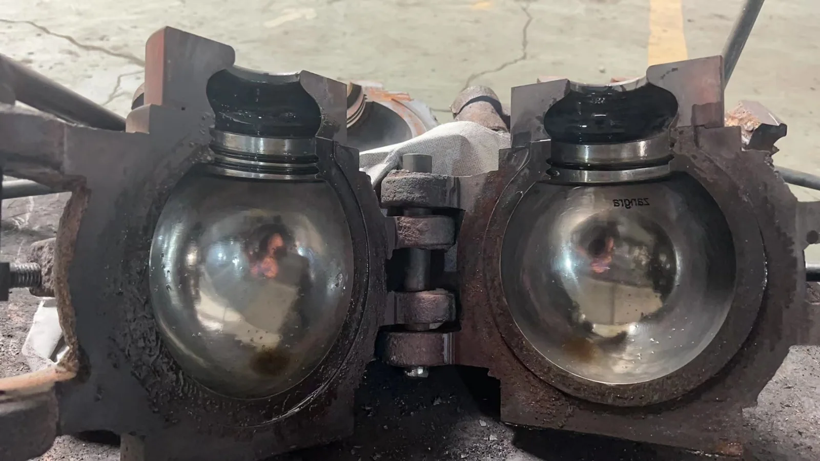
A raised seam can justify checking registration, closure, mating surfaces and deposits. Drag marks direct attention towards relative movement during release or handling. Neither observation alone establishes the root cause.
Compare start-up with sustained production, new with used tooling, and preparation before and after renewal. Inspect both the mould and the part; an apparently clean cavity does not exclude a problem elsewhere in the contact sequence.
Wrinkles and folds also warrant review of gathering, preform preparation and thermal history. Check whether a later support or annealing contact adds a mark that was absent at release.
For sticking, examine the actual material and preparation method. Moisture is intentional in established wet wooden-mould processes, as described in Blenko's account of its mould work; that practice does not prescribe treatment for metal, graphite or other systems. Check deposits, lining condition and obstructed air paths where relevant.
Record polishing, vent changes, preparation products and repairs as controlled changes. Verify geometry, release behaviour and appearance afterwards: removing a visible mark can also change a forming surface. A cosmetic improvement alone is insufficient if the modification alters fit or local thickness.
5. Check Openings, Bases and Applied Features
Local features often acquire their final condition after the main body is formed. Compare an opening before and after transfer, rim working, trimming, grinding and fire polishing. Follow material availability, alignment, tool contact and heating at each stage.
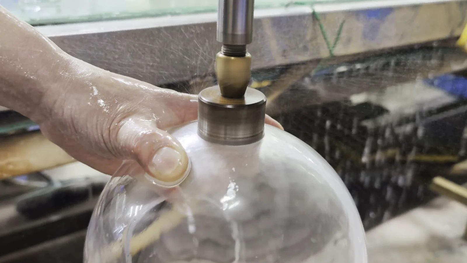
For mounting problems, inspect the complete interface. Diameter alone may pass while ovality, rim angle or a local high point prevents seating. Use the specified holder, gauge or mating component with the intended support and contact conditions.
For a rocking base, distinguish a formed-profile error from a protruding attachment mark, support deformation or uneven finishing. Check the intended contact ring or standing area rather than assuming the entire underside must be flat. Compare before and after removal of material.
For handles, feet or stems, review location, junction geometry, added quantity, joining sequence and support. Identify the actual material combination where glasses remain fused together, using compatibility evidence appropriate to the glasses. Matching appearance does not establish compatibility, and further heating should not be assumed to correct an incompatible combination.
Verify the characteristic affected by the original problem and those affected by the proposed repair. Reheating can change alignment and thermal history; grinding can change remaining thickness and the seating plane. Repeat the relevant dimensional, stress and functional checks on the completed condition.
6. Inspect Internal Bridges, Projections and Loose Glass
Inspect hollow interiors from enough directions to examine the required regions. A single external view can miss a bridge, attached projection or particle behind an opening or shoulder.
In Bucher Emhart's container-defect terminology, “bird swing” describes a thin internal glass bridge. The descriptive term does not establish an identical forming cause in every manual process. Distinguish a continuous bridge from a projection attached to one wall, an adhering particle and a loose fragment.
Record attachment points, size, location and whether the feature changes position. Establish whether it is present before trimming or later handling. Preserve an uncleaned comparison where contamination evidence may be useful.
Review the corresponding forming stage, contact surfaces, trimming operations and handling environment. Consider air paths only in relation to the actual equipment and evidence, rather than importing an automated-machine remedy.
Unintended sharp projections, bridges and loose glass require containment and a defined disposition. They should not pass under a general allowance for decorative variation. Cleaning can remove loose material without addressing an attached feature or the source introducing fragments.
Any rework needs inspection access sufficient to establish the internal condition and verification that the remaining wall, openings and other requirements remain acceptable. Record the affected batch and reinspection results.
7. Investigate Cracks, Breakage and Residual Stress
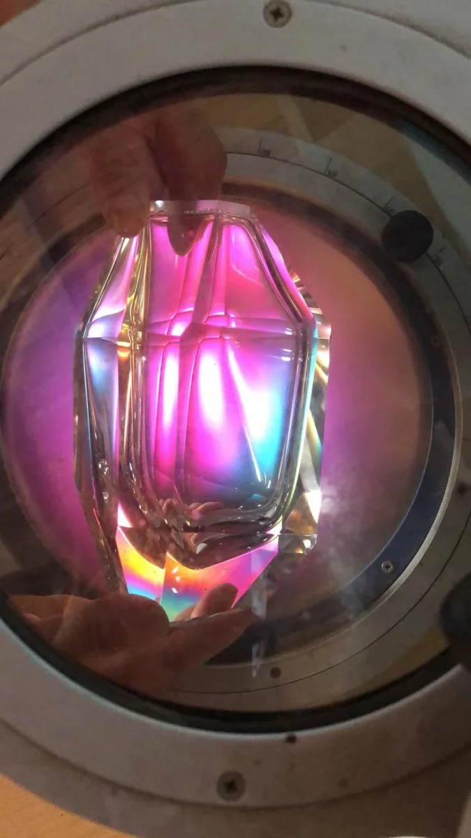
A check is a crack, including a short or difficult-to-see one. Record its orientation and relationship to edges, seams, contact points, inclusions or junctions. Thermal gradients, residual stress, mechanical damage, fit and material incompatibility may contribute together.
Swipe horizontally to view all columns.
| Failure context | Evidence to preserve | Checks to consider |
|---|---|---|
| Forming or transfer | Early observations and contact sequence | Local cooling, support and deformation |
| Annealing or unloading | Load identity, positions and profile records | Incoming condition, thermal history and handling |
| Finishing | Incoming and intermediate samples | Locating, support, tool contact and earlier damage |
| Assembly or use | Mating parts, fragments and exposure history | Seating, loads, damage and temperature changes |
These are investigation routes, not diagnoses. Preserve available fragments and their original relationship. ASTM C1256 addresses identification and interpretation of fracture-surface features, not a complete fractographic procedure. Specialist fracture examination may help locate an origin and assess loading; a late failure does not automatically prove inadequate annealing.
A completed programme or intact cooled piece does not demonstrate acceptable residual stress. Check the inspection method, orientation, optical path and instrument condition before interpreting an unexpected result. Optical retardation is not directly interchangeable with a stress value; material properties and glass thickness affect that relationship, and the interpretation must suit the geometry.
Then review glass identity, heavy sections, entry condition, loading, supports, effective thermal treatment and interruptions. Include subsequent fire polishing or decoration firing: an earlier annealing record does not establish the condition after additional heating.
For a defined stress problem, further treatment may be evaluated, but it does not establish repair of existing cracks. Verify stress, shape, surfaces and heat-sensitive appearance after a thermal change. Keep cracks and other damage subject to their own acceptance criteria.
8. Separate Cloudiness, Colour and Finishing Defects
Determine whether cloudiness is removable residue, a surface condition, a treatment effect or a feature within the glass. Use consistent lighting and comparisons of similar thickness and geometry. Preserve evidence before selecting a cleaning or removal trial.
Confirm suspected crystallisation through suitable examination before calling it devitrification. A hazy appearance alone cannot establish a crystalline phase or identify its origin.
For colour differences, distinguish body glass from layers, coatings and decoration. Wall variation changes the optical path, while some colours respond to thermal history. Compare material references, reheats, firing records and finished treatments before attributing the difference to the supplied grade.
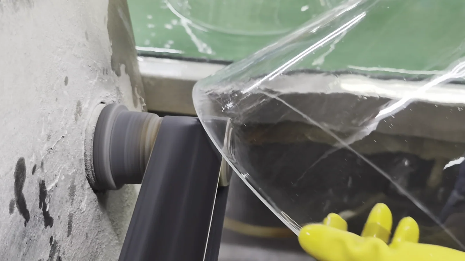
Follow chips, uneven rims or polishing marks through incoming and intermediate finishing samples. Check support, alignment, abrasive condition, removal and contamination between operations. Finding a flaw after grinding does not establish that grinding created it.
For coatings and decoration, classify the failed characteristic: adhesion, coverage, colour, gloss, pinholes, registration, masking or handling damage. Examine preparation and the actual recesses, edges and interfaces; a flat trial panel may not represent the product.
After stripping, recoating or polishing, inspect the underlying glass and requirements the rework can alter. Verify the intended treatment function as well as appearance. For lighting products, assess the specified illuminated condition where unlit inspection can conceal variation.
9. Verify Corrective Actions and Prevent Recurrence
Keep an unverified explanation labelled as a hypothesis. Record the observations supporting it, competing explanations, the change tested and the results. The aim is to test the proposed mechanism, rather than select a remedy solely because the defect looks familiar.
Swipe horizontally to view all columns.
| Change tested | Related requirements to recheck |
|---|---|
| Gather or preform | Weight, thickness distribution and geometry |
| Reheating or inflation | Profile, local thickness and surfaces |
| Mould repair or preparation | Dimensions, seams, release and appearance |
| Thermal cycle | Residual stress, shape and heat-sensitive effects |
| Finishing or coating | Edges, fit, appearance and intended function |
Use controlled trials and record interacting conditions. Where repeated individual adjustments obscure the relationship, a planned experiment may be more informative. Include representative start-up, sustained production and restart conditions when they contributed to the original event.
Confirm improvement on finished components using the original acceptance method or a justified replacement. A successful trial does not automatically release earlier affected stock. Define separate decisions for the corrected process, held production and reworked components.
Retain the link between samples, material, tooling, process revision and batch disposition. Update instructions, maintenance and inspection criteria when the action is approved. Monitor later production for recurrence and check that the action remains effective after the relevant routine changes.
Close the investigation when the evidence supports the correction, affected production has a recorded disposition and the revised controls can be followed in production. Record any remaining limitation rather than presenting a plausible explanation as a proven root cause.
References
- Blenko — Mould Stuff: Moulds, Moulds, Moulds: its wet wooden-mould method and preparation context.
- Bullseye Glass — TechNotes 3: Compatibility of Glasses: evidence for compatibility between joined glasses.
- Hinds Instruments — Stress Measurement: optical measurements and differential stress.
- SSV — Gas Bubbles Analysis: specialist identification of gases within glass bubbles and blisters.
- Bucher Emhart Glass — Defect Guide: container-defect terminology and descriptions.
- ASTM International — C1256-25a: identification and interpretation of fracture-surface features.
Contact Us
Discuss Your Custom Glass Project
Share your drawing, photos or dimensions, together with the intended use and target quantity. We will review your requirements and discuss the next steps.
Sales Enquiries
Email sales@bo-glass.com with your part description, intended use and target quantity.
Send Your Design
Use the form to upload a drawing or describe an existing part. Mark critical dimensions and tell us which surfaces or features matter most.
Request a Custom Glass Quote
Upload a drawing or share dimensions, quantity, intended use and finish. Include any heat, pressure or chemical exposure.
Your drawings remain confidential.
We use the contact details you provide to respond to your enquiry. See our Privacy Policy for more information.