
Blowpipes, Moulds and Tooling for Molten Glass Blowing
Tooling links a product design to the way glass is gathered, supported, shaped and finished. This guide helps designers, engineers and purchasing teams define the requirements that matter, compare tooling arrangements and assess evidence from production trials.
Quick-start: prepare these five items
- Product drawing or concept, including critical dimensions and assembly interfaces.
- Glass specification, appearance requirements and intended surface details.
- Acceptable seams, contact marks and attachment marks, identified by location.
- Sample quantities, expected orders and the proposed finishing condition.
- Approval criteria, inspection references and tooling ownership requirements.
1. Define the Tooling Scope and Responsibilities
Start by allocating each product feature to an operation. A mould may establish the body while hand tools form the opening; cutting or grinding may then establish a mounting face. Identify what is formed directly, adjusted during working, created during transfer or completed after annealing.
The customer defines the required product, fit, appearance and acceptance conditions. The manufacturer selects and validates tools, supports and operating methods for the chosen glass and production arrangement. Review these responsibilities together before treating a tooling drawing as a complete manufacturing plan.
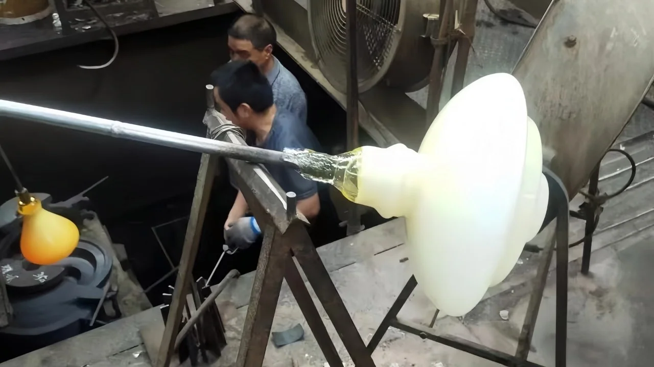
Free blowing relies on inflation, rotation, gravity and hand tools. Mould blowing adds requirements for cavity entry, closure, displaced-air escape and release. Products can combine both routes, so the tooling scope should follow the complete sequence rather than stop at the body mould.
Identify dedicated blowpipes, inserts, forming tools, transfer supports, fixtures and gauges where needed. Confirm which items are existing equipment and which require development. Mechanised systems also need review of their delivery, holding and air-control arrangements; their features should not be assumed necessary for a manual furnace workstation.
For example, a pendant shade may need a body mould, a fixture locating a later cut and a gauge representing its holder. These items address different requirements; approving the body shape alone would not demonstrate the mounting fit.
2. Select Blowpipes and Blowing-Air Connections
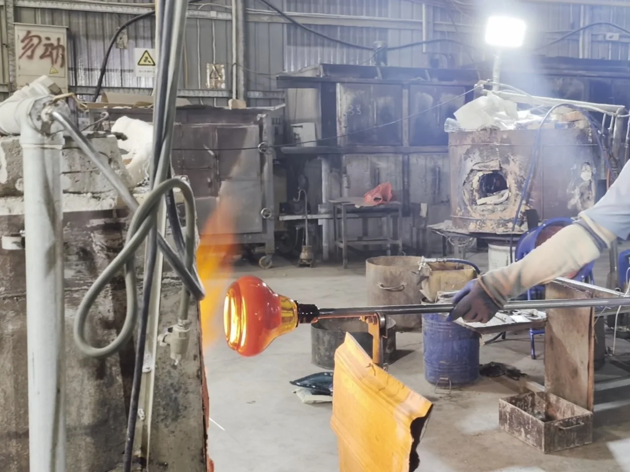
A blowpipe supports the developing piece and provides the air passage for inflation. Selection must accommodate gathering, rotation, reheating, mould entry and transfer.
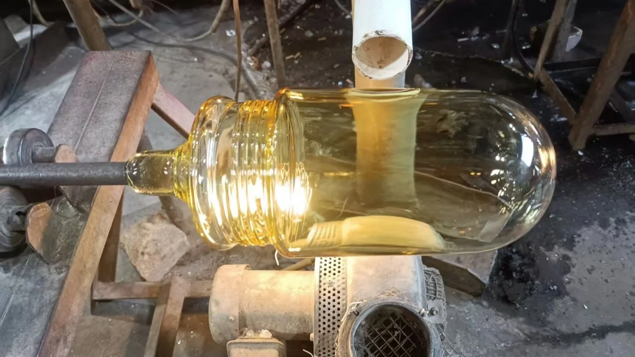
Review carried glass weight, pipe length, shaft dimensions, balance, resistance to deformation and head geometry. Check access to furnace openings and compatibility with benches, rollers and supports. Evaluate the complete construction, including the head and joints; a broad shaft-material description does not establish suitability.
Before use, inspect straightness, joints, loose components, head surfaces and the air passage. Loose scale near the glass-contact area, damaged attachment surfaces or restrictions in airflow need attention under the tool's preparation procedure. Replacement tools with different dimensions or balance require a check against the established sequence.
Air may enter through a mouthpiece, a purpose-made extension hose or an assisted system. Match connectors and seals to the pipe. Where rotation is required, check the connection's freedom of movement and route hoses to avoid kinking or interference with hot work.
For assisted systems, review valve response, shutoff, regulation, limiting functions and air cleanliness appropriate to the product. Pressure, flow and application time describe different conditions; a regulator setting alone does not characterise delivery to the glass. Identify the measurement point and whether readings represent static supply or operation during blowing. Establish settings through the actual equipment and product response.
3. Plan Hand Tools, Transfers and Workstations
Select tools around the feature they must reach and the condition they must leave. Their contact can change local temperature as well as shape.
The Corning Museum of Glass tools overview describes blowpipes, punties and the roles of common furnace-working tools.
Swipe horizontally to view all columns.
| Feature or operation | Tooling to consider | What to verify |
|---|---|---|
| Rolling and shaping a gather | Marver | Cleanliness, flatness and surface damage |
| Supporting and rounding | Wooden block | Profile, wear and preparation condition |
| Neck or opening formation | Jacks | Blade profile, alignment and contact marks |
| Local flattening or shaping | Paddle | Contact-face condition and working access |
| Hot cutting and trimming | Shears | Edge condition, alignment and resulting edge |
| Pulling or positioning details | Tweezers or pincers | Tip condition, reach and permitted marks |
For a critical feature, identify the working profile used during development. A replacement with a different contact face may need a new feature check even if it performs the same general task.
A punty, or pontil, temporarily supports the piece after separation from the blowpipe, often while its mouth is opened or shaped. Establish whether transfer is needed, the attachment location, centring method, support and removal sequence. Agree whether the attachment area retains a mark or receives grinding or polishing.
Supports must accommodate the intermediate shape and changing balance, including wide, heavy or asymmetric work. A fixture matching the final drawing may not fit the piece during transfer.
Arrange gathering, bench work, mould opening, reheating and transfer with adequate clearance. A reheating furnace, often called a glory hole, must accommodate the largest intermediate form and its supporting tools. Reheating during shaping and final annealing have different purposes; the workstation needs access to both stages. Check rollers and supports for wobble, slipping and interference during rotation.
4. Choose the Mould Type and Material
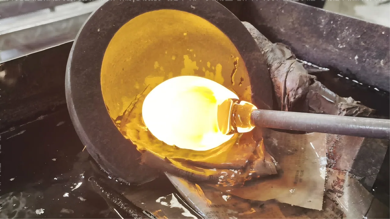
Choose how the cavity functions before selecting its material. An open or dip mould may shape part of a body. A pattern mould can create details that change during later expansion. A split mould permits release where a single open cavity would not.
Turning and stationary arrangements serve different designs. Rotating the glass inside a suitable mould can support smooth, rotationally symmetric forms; stationary arrangements may preserve asymmetry or defined details. The Corning Museum of Glass FAQ provides background on these mould-blowing distinctions. How a mould opens and whether the glass rotates inside it are separate choices: a split construction does not itself establish stationary forming.
Swipe horizontally to view all columns.
| Mould material | Selection question | Evidence to review |
|---|---|---|
| Wood | Does an established wooden-mould method suit the shape and surface? | Preparation, profile wear, storage and sample consistency |
| Metal | Does the construction suit the profile, details and production conditions? | Thermal behaviour, surface condition, corrosion and maintenance |
| Graphite | Is the grade suitable for the proposed contact and forming method? | Surface integrity, handling, wear and trial results |
Material choice belongs with the surface interaction, opening arrangement and production rhythm. Consider maintenance, replacement and subsequent finishing alongside initial tooling cost. A material name alone does not establish service life or finished-product quality.
Compare proposals against the required profile, texture, mark limits and planned output. Ask what trial evidence will establish suitability and what condition will trigger maintenance, rather than choosing from a material label alone.
5. Design the Cavity, Release and Mould Assembly
A blowing mould primarily influences contacted exterior surfaces. Internal contour and wall distribution also depend on glass quantity, initial shape, temperature and inflation. A cavity inspection therefore cannot establish every finished-part requirement.
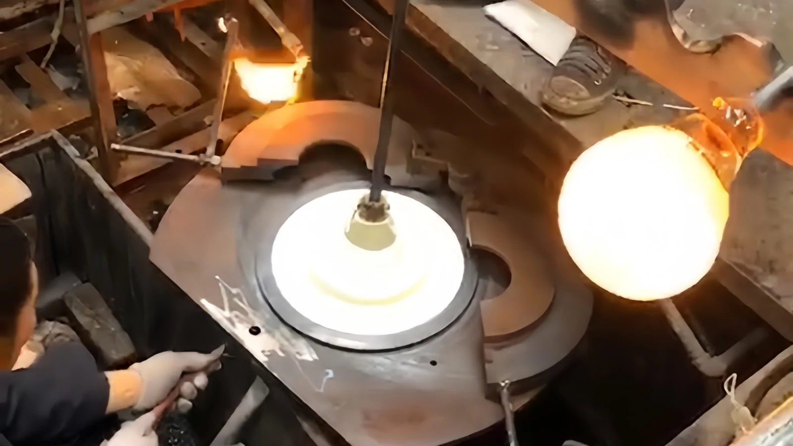
Review entry clearance, shoulders, corners, recesses, parting lines and extraction directions. Identify undercuts or projections needing separate sections, and leave access and allowance for later finishing. Record which critical surfaces are formed together and which are established afterwards.
Establish dimensional compensation using the selected glass, forming route and sample results. Avoid applying a universal shrinkage percentage. Final dimensions must correspond to the specified condition after annealing and finishing.
For assembled moulds, check hinges, locating surfaces, stops, holders, removable bases and inserts. Sections should register consistently, close to the intended position and open without interfering with the glass. Clean mating surfaces and correctly seated inserts are part of that assessment.
Identify matched components and permitted combinations. Hinge or locator wear can change the cavity even when its working surfaces look sound. After repair or replacement, inspect the assembled tool and resulting glass, not just the individual component.
Specify acceptable seam locations and appearance. Construction, forming method and subsequent operations affect visibility; a mould-blown product does not inevitably retain a prominent seam.
6. Control Venting, Temperature and Surface Preparation
Keep different air functions identifiable when reviewing the forming system.
Swipe horizontally to view all columns.
| Air function | Purpose | Applicability |
|---|---|---|
| Inflation | Expands the glass from inside | Through the blowpipe or selected assisted arrangement |
| Cavity venting | Releases displaced air outside the expanding glass | Defined by the mould and release arrangement |
| Mould cooling | Removes heat through designated surfaces or passages | Where provided by the tooling system |
| Blow-head exhaust | Supports intended circulation through the blowing arrangement | Applicable mechanised systems |
Review where displaced cavity air travels and whether deposits, inserts or treatments can obstruct that path. Vent geometry can affect visible marks. Record changes to holes, slots or joint relief and evaluate them through trials; there is no universal vent size.
Mould temperature influences heat transfer, release and shape retention. Establish conditions for start-up, normal production and restart after pauses or changes. Record measurement location, method and cycle stage; an external reading need not represent the glass-contact interface. Identify available cooling controls and validate their effect rather than increasing cooling without understanding the problem.
Bucher Emhart's container-forming cooling options illustrate equipment-specific arrangements in mechanised production. They provide context, rather than cooling specifications for a manual furnace workstation.
Surface preparation must match the material and method. In a validated wet wooden-mould process, moisture and the resulting steam are intentional parts of the forming arrangement, as described in Blenko's account of its mould work. That practice does not establish a preparation method for metal, graphite or other moulds.
For linings, pastes, lubricants or release treatments, define the product, preparation, application areas, condition before use and renewal criteria. Keep required air paths clear and inspect for deposits or loose material. A treatment change can affect release, surface appearance and local heat transfer even when the cavity geometry remains unchanged.
7. Maintain Tooling and Control Revisions
Use condition and product results to guide maintenance. Increasing marks, altered seams, closure variation, release problems or dimensional drift can indicate a need for investigation.
Checks should cover pipe straightness and head condition, air passages, hand-tool surfaces, cavity wear, deposits, locating features, vents, cooling passages and supports. Establish intervals from experience with the actual tool and working conditions.
Separate routine cleaning from work that changes a forming surface or assembled geometry. Cavity polishing, vent enlargement, insert replacement and support modification may change the product. Record the work, update tool identification where necessary and determine which results need rechecking.
Assess repairs against the actual tool manufacturer's information and the tool's condition. Do not assume that every pipe or mould can undergo the same repair. Verify replacement or repaired assemblies before returning them to the established process.
For example, Spiral Arts lists straightening and head-replacement services for tools it accepts for repair. Such services illustrate possible interventions, not a general assurance that another construction can be repaired in the same way.
Keep tool revisions linked to sample and production records. Where several moulds or interchangeable sections are used, distinguish them so a quality change can be traced to the relevant arrangement.
8. Approve Tooling with Gauges and Production Trials
Fixtures, templates and gauges should address defined features at a defined stage. They may check profile, height, opening, handle position, base seating, alignment or mating-part fit.
A hot-forming template is an in-process reference. Final acceptance checks must represent the condition supplied, after the operations affecting the requirement. Define measurement references, support and method, and ensure fixtures do not force the glass into a misleading position or damage visible surfaces. For fit gauges, identify the mating geometry represented.
Tool inspection verifies drawings and assembly. Production trials establish whether the system produces the required glass.
Swipe horizontally to view all columns.
| Trial record | Decision it supports |
|---|---|
| Tool identity and revision | Which moulds, inserts, tools and fixtures were evaluated? |
| Glass and starting condition | Were material and forming inputs representative? |
| Preparation and operating sequence | Which surface, thermal and cooling conditions produced the samples? |
| Sample identification | Can each result be traced to its trial conditions? |
| Annealing and finishing route | Does inspection represent the specified final condition? |
| Product inspection | Were dimensions, wall distribution, appearance and functional fit demonstrated? |
One successful piece may not establish repeatability. Choose representative samples and include restart or tool-change conditions where they affect production. Check standing stability and assembly where required, alongside dimensional and appearance criteria.
Record limitations, deviations and the evidence needed to resolve them. A satisfactory hot shape does not establish final dimensions, residual stress or the appearance after finishing. Confirm production expectations against the completed sample assessment.
9. Define Tooling Scope, Ownership and Quotation
A useful tooling enquiry includes the drawing or model, glass specification, critical sections, openings, rims, bases and assembly interfaces. Identify visible areas, permitted seams and marks, finishing requirements, sample quantities and expected orders. Provide references and mating components where they constrain the design.
The quotation should state which moulds, inserts, dedicated hand tools, supports, fixtures and inspection gauges are included. Identify development and trial work separately enough to establish what approval demonstrates, without assuming the mould alone constitutes the complete tooling scope.
Clarify ownership, identification, storage, maintenance, repair and replacement responsibilities. Where service life is discussed, record the production assumptions and the condition requiring repair or replacement. Establish how changes affecting the product will be reviewed.
These details support comparison of tooling proposals against the same finished-product requirements, sample evidence and ongoing supply responsibilities.
References
- Corning Museum of Glass — Glassblowing Tools: blowpipes, punties and forming-tool roles.
- Corning Museum of Glass — Frequently Asked Questions: background on mould-blowing methods.
- Blenko — Mould Stuff: Moulds, Moulds, Moulds: mould materials and its wet wooden-mould process.
- Spiral Arts — Repairs: examples of manufacturer-specific tool repair services.
- Bucher Emhart Glass — Cooling Options: cooling arrangements for mechanised container-forming equipment.
Contact Us
Discuss Your Custom Glass Project
Share your drawing, photos or dimensions, together with the intended use and target quantity. We will review your requirements and discuss the next steps.
Sales Enquiries
Email sales@bo-glass.com with your part description, intended use and target quantity.
Send Your Design
Use the form to upload a drawing or describe an existing part. Mark critical dimensions and tell us which surfaces or features matter most.
Request a Custom Glass Quote
Upload a drawing or share dimensions, quantity, intended use and finish. Include any heat, pressure or chemical exposure.
Your drawings remain confidential.
We use the contact details you provide to respond to your enquiry. See our Privacy Policy for more information.