
Annealing, Cooling and Pressed Glass Quality Inspection
A practical guide to validating annealing conditions, controlling cooling and defining inspection requirements for molten-pressed glass components.
A component can leave the mould with the intended shape and still develop residual stress, distortion or cracking during cooling. A useful annealing specification connects the glass and geometry with the actual thermal history, then verifies the characteristics required at the agreed product stage.
Define the Thermal Route and Acceptance Stage
Start with the condition of the article, not just the furnace programme. A newly pressed component transferred while hot and a previously cooled component being reheated need separately validated entry conditions. Neither route has a universal temperature schedule.
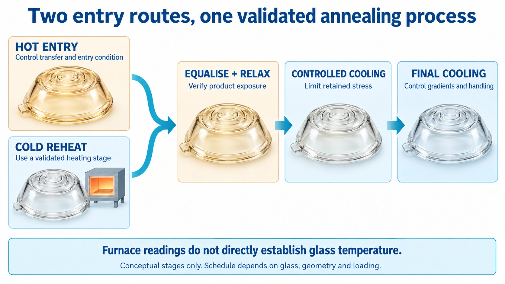
Record mould or station identity, demoulding condition, transfer interval and any hot finishing. These operations affect the temperature distribution entering annealing. Link each sample to its production interval or batch so that later results can be traced back to both forming and thermal processing.
Annealing allows unwanted residual stress to relax and controls its development during subsequent cooling. It does not remove existing cracks, bubbles or inclusions. Specify a measurable acceptance condition instead of describing the product as completely stress-free. MO SCI explains the purpose of glass annealing.
Identify the condition being accepted
State whether requirements apply to the pressed-and-annealed blank, the finished component, or the coated, strengthened or assembled product. Allowances and acceptance limits may differ between these stages.
Annealing and strengthening have different objectives. Thermal or chemical strengthening deliberately establishes a stress distribution; its acceptance method must suit that treatment. An annealed-blank report cannot establish the final strengthened condition.
Use Thermal Data for the Actual Glass
Obtain applicable thermal data for the production grade and retain the supplier, material designation and relevant reference conditions. A broad family name such as soda-lime or borosilicate does not identify one annealing programme.
| Material reference | Meaning for process development |
|---|---|
| Annealing point | A viscosity-related reference that helps identify a useful stress-relaxation region. |
| Strain point | A lower-temperature reference where relaxation becomes much slower; it is not a guarantee against thermal cracking below that temperature. |
| Transformation temperature, Tg | A reference within the glass transition region, dependent on the measurement convention; not automatically interchangeable with the annealing point. |
| Softening point | A deformation-related reference under defined test conditions, not a universal boundary below which shape cannot change. |
These values guide development; they do not independently determine hold time, cooling rate or loading limits. SCHOTT's mechanical and thermal property guidance explains the reference temperatures for optical glasses. Apply data appropriate to the actual glass rather than transferring an optical-glass example into a production recipe.
Review the existing validation when grade, composition or supplier changes.
Match the Furnace, Entry Conditions and Loading
Choose equipment around the production flow, article geometry and required thermal response. A continuous lehr moves articles through zones; a batch furnace processes a defined load through a programme over time.
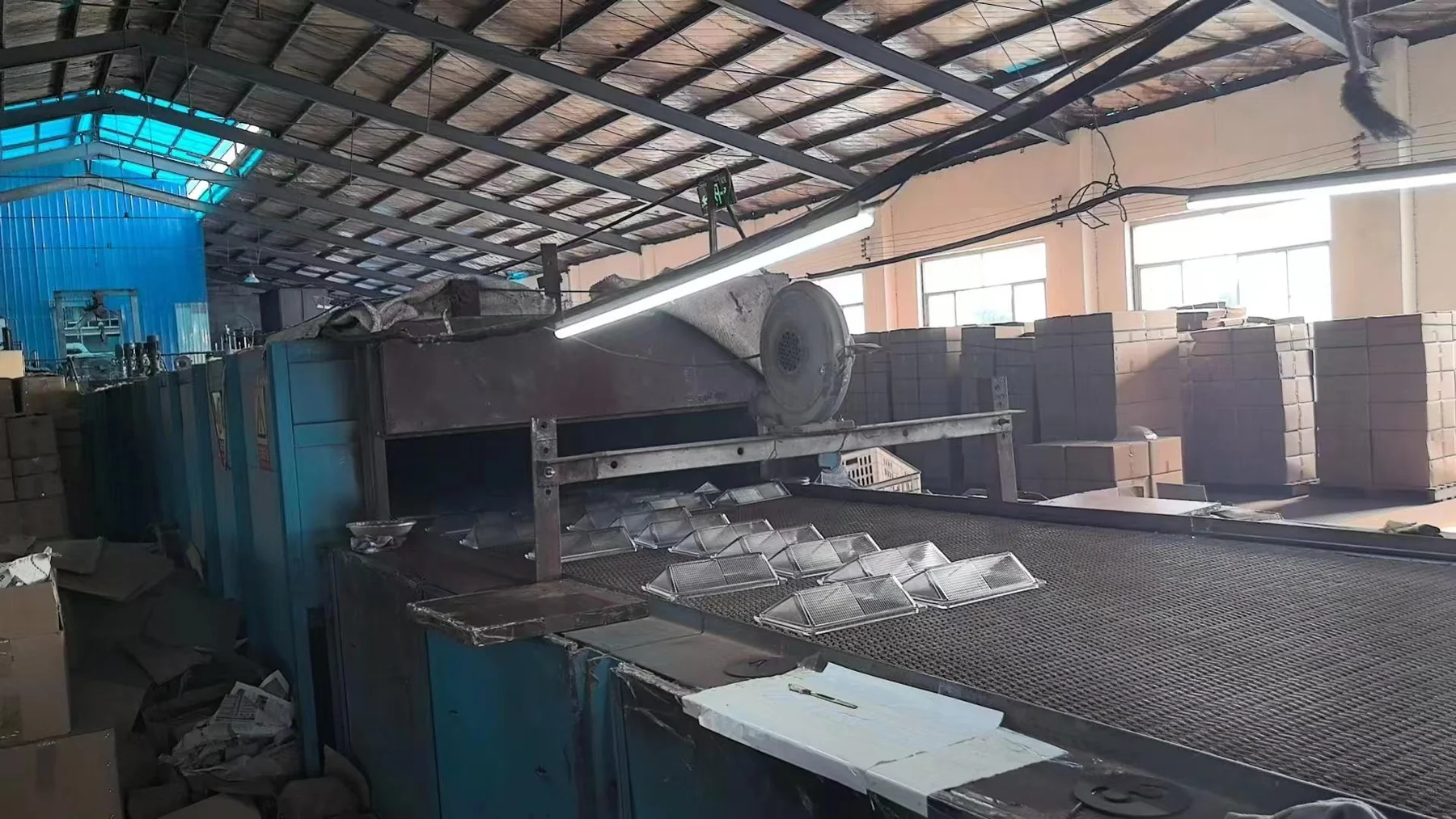
| Control item | Continuous lehr | Batch furnace |
|---|---|---|
| Thermal exposure | Entry condition, zone profile and actual belt movement | Entry condition, heating stages, holding and cooling |
| Load definition | Spacing, orientation, lane and production rate | Quantity, orientation, shelves, supports and load positions |
| Verification coverage | Relevant lanes and operating conditions | Relevant positions and load arrangements |
| Traceability | Entry time, lane and operating records | Batch identity and position within the load |
Equipment examples include Vidromecânica's conveyor annealing lehrs and Nabertherm's glass annealing furnaces. Their configuration must be evaluated for the intended product and load.
At constant belt speed, zone length divided by speed gives residence time. It does not establish the temperature inside the glass. Record speed changes and stoppages when reconstructing actual exposure.
Define support and contact conditions
Specify transfer limits, orientation, spacing, loading density and permitted product combinations. Identify contact areas and inspect trays or fixtures for contamination, wear and changes in support geometry.
Supports influence both heat transfer and deformation. Nesting, stacking or mixed loads require validation because they change exposure and contact conditions. Similar external dimensions do not establish equivalent thermal behaviour.
For cold reheat, validate the heating stage as well as subsequent annealing and cooling. Delayed hot transfers also require assessment against the established entry conditions.
Validate Equalisation and Holding for the Geometry
Temperature equalisation reduces relevant differences within the article; stress relaxation needs adequate exposure at suitable temperatures. These processes can overlap, but a furnace sensor reaching setpoint does not establish that the glass surface, core and shielded regions have reached the required condition.
Establish when holding time starts
For batch processing, define the condition that starts the hold. Routine control sensors may support that decision only where development work has demonstrated their relationship to the product and loading arrangement.
For continuous processing, validate the combination of entry condition, thermal zones and residence time. Representative instrumented articles, suitable test pieces or a thermal model checked against measurements can support development. Document their relationship to the production part and the limits of any indirect routine method.
Retain actual temperatures, holding or residence times and interruptions, together with the programme revision.
Check the features that respond differently
A heavy base, thin wall, thick flange, mounting boss or deep recess can create local differences that maximum thickness alone does not describe. Review thick-to-thin transitions, asymmetric geometry, unsupported spans and concentrated support contacts.
Evaluate stress and geometry at related locations: for example, flange flatness together with stress around the flange-to-wall transition. Changes to holding temperature, duration, orientation or support may improve one result while worsening another.
Do not extend a validated schedule to another article solely because its maximum thickness matches. Define the material, geometries and loading arrangements covered by the evidence.
Control Annealing-Range and Final Cooling
Cooling has two related objectives: limiting retained residual stress and avoiding damage from temperature gradients throughout the cycle. A longer initial hold cannot automatically compensate for an unsuitable cooling profile.
During cooling through the region where stress can still relax, verify the profile using representative articles and loading conditions. Assess the resulting residual stress after the components reach the specified inspection condition.
At lower temperatures, relaxation may become too slow to contribute meaningfully during production. Faster cooling may then be possible, but transient thermal stress can still cause cracking. Glass type, section transitions, surface condition, support and local heat transfer remain relevant. SCHOTT's guidance on thermal loads explains these dependencies.
Define unloading and transfer conditions, including contact with cooler surfaces and exposure to local airflow. Establish when parts are sufficiently temperature-stable for dimensional and optical measurement; being convenient to handle is not itself a measurement criterion.
Retain records of power interruptions, belt stoppages, cooling changes and delayed transfers. A normal controller display after restart does not establish that affected articles experienced an acceptable cycle. Use the containment and disposition process described below.
Specify Residual Stress Inspection and Its Limits
Polarised-light inspection can reveal stress-related optical effects in suitable transparent glass. A polariscope commonly supports qualitative observation; quantitative results require an appropriate instrument and method. Strainoptics describes the distinction between strain viewers and polarimeters.
Define the acceptance method before testing. “Stress checked” is insufficient unless the record identifies what was evaluated and how the decision was made.
| Specification item | What to define |
|---|---|
| Product stage and coverage | Annealed or final condition; named regions, edges and transitions; areas the method cannot evaluate |
| Reported quantity and units | Optical retardation in nm, path-normalised retardation such as nm/cm, or an appropriately interpreted stress value in MPa |
| Geometry and optical path | Viewing direction, orientation sequence and actual path through the glass, including curved or overlapping walls |
| Instrument and method | Configuration, wavelength or filter, calibration or reference checks and measurement procedure |
| Interpretation | Applicable material coefficient and assumptions if converting optical data to stress |
| Acceptance rule | Limit for the stated quantity and region, sampling requirements, and the decision rule for results near a limit |
Keep optical measurements and stress values distinct
Retardation is an optical path difference. Path-normalised retardation divides that result by a defined light-path length. Neither is automatically a mechanical stress value.
Stress interpretation depends on the glass's stress-optical coefficient and measurement geometry. A transmission measurement does not recover the complete local stress state. For curved or overlapping walls, do not substitute nominal wall thickness for the actual optical path without justification.
A dark appearance at one orientation is not proof of zero stress; orientation can suppress the observed signal. SCHOTT's stress measurement guidance explains these relationships. Limits for raw optical glass should not be adopted as finished-product acceptance limits without an applicable specification.
Address opal and strongly coloured glass explicitly
If transmission, scattering or geometry prevents the selected method from evaluating a critical region, record the limitation. An unreadable region is not a passing result.
Agree and validate an alternative assessment suited to the product. Define its coverage, sensitivity and relationship to the acceptance requirement. Transparent witnesses or other representative specimens need evidence that they represent the relevant material and thermal response; visual similarity alone is insufficient.
Application tests may contribute to an agreed acceptance plan, but do not report them as a direct residual-stress measurement. Where the agreed requirement cannot be evaluated, resolve the method or specification before release.
Verify Dimensions, Surfaces and Assembly Fit
Inspect at the specified product stage and temperature condition, using the correct drawing revision, datums and supports. Link results to identifiable articles so that variation can be compared with forming, loading and thermal records.
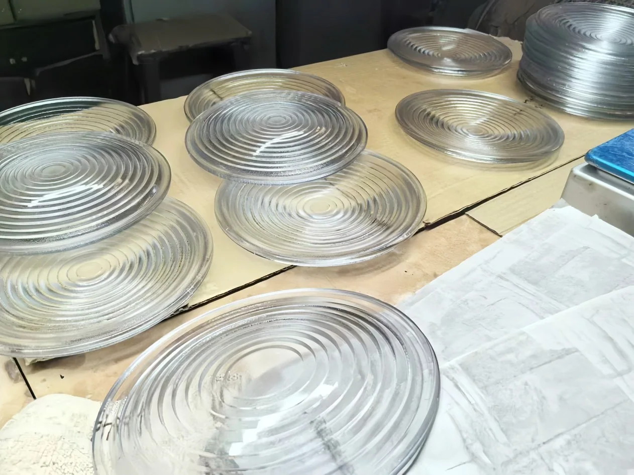
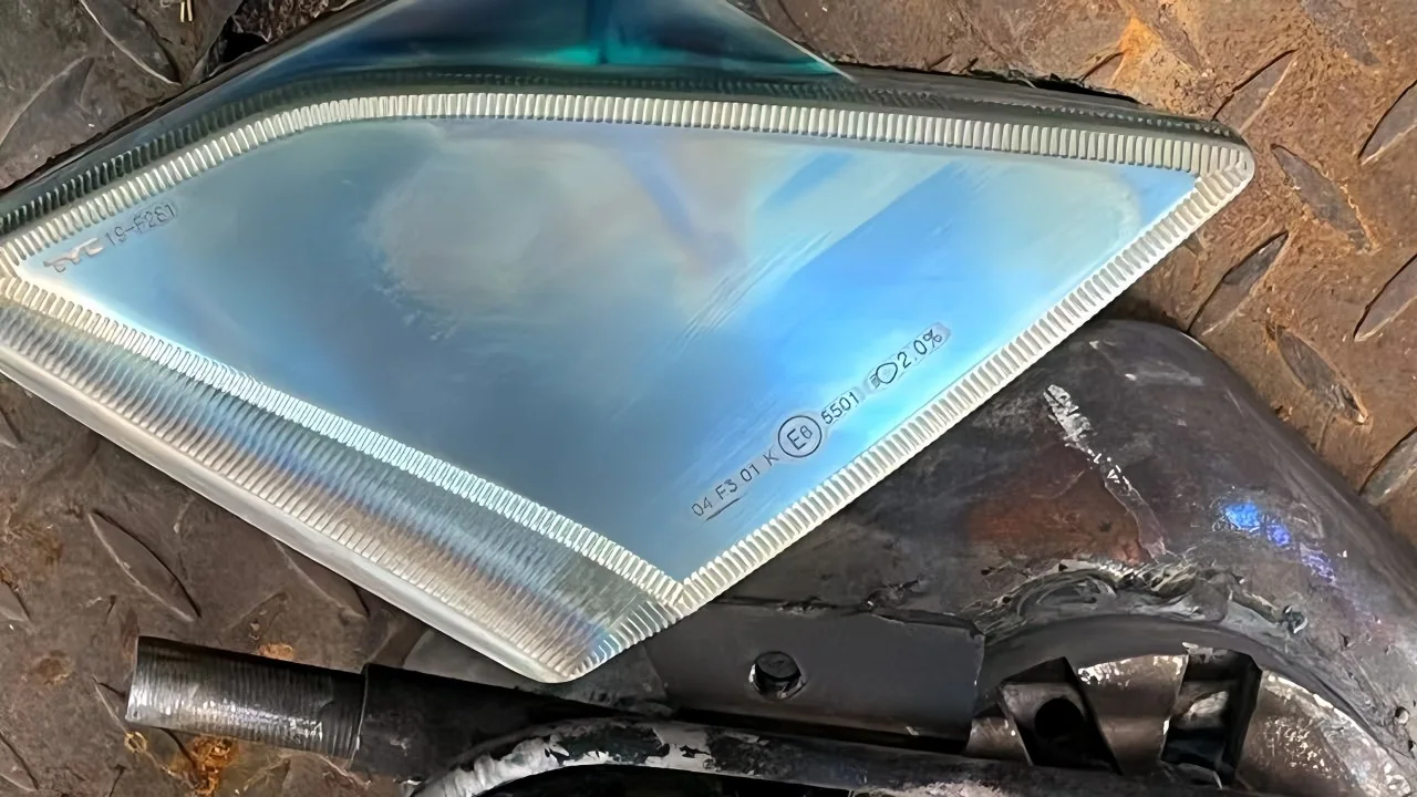
Select measurements from the functional features: overall dimensions, wall and base thickness, rim or flange flatness, roundness, profile, holes, threads, and mounting or sealing interfaces. Define the measurement locations and any permitted forming or support marks.
Make the inspection repeatable
Optical measurement can be affected by transparency, reflection, texture and curved interfaces. Contact measurement needs suitable access and controlled contact conditions. Establish that the method can resolve the actual feature; instrument resolution alone does not establish accuracy.
For visual inspection, specify cleaning, lighting, background, viewing distance, orientation and magnification where needed. Separate surface defects, edge damage and internal features, and set acceptance by type, size, count and location. Identified reference samples can support appearance criteria.
Distinguish primary viewing areas, secondary surfaces, edges and mounting or sealing zones. Crack-like indications need appropriate evaluation; cosmetic criteria should not release damage in a critical region.
Check the relevant assembly conditions
Use a defined mating part or controlled gauge for functional fit. Record seating, alignment and fastening conditions, including gaskets or retaining rings where they affect the result. A fit check alone does not establish sealing or performance under service loading.
Verify Application Performance
Select optical, thermal and mechanical tests from the component's intended function. Material data, acceptable residual stress and a successful fit check each provide useful evidence, but none establishes every aspect of finished-product performance.
| Test area | Conditions that make the result meaningful |
|---|---|
| Transmission and colour | Spectral range, optical path, incidence, surface state, collection geometry, illuminant and reference |
| Lighting or optical function | Intended source and assembly, with the required beam distribution, diffusion, spectral or imaging result |
| Thermal performance | Initial condition, exposure medium, temperature change, transfer interval, dwell, cycles and support or assembly |
| Mechanical performance | Load direction, contact and support geometry, edge condition, assembly preload and failure criterion |
For textured or light-redirecting components, define how redirected light is collected. Light missing a narrow detector aperture should not automatically be treated as absorption. Keep internal material transmittance distinct from the finished-component result. SCHOTT's transmittance guidance explains the underlying distinction.
Separate qualification testing, which establishes evidence for the design and manufacturing route, from routine inspection, which monitors production under the agreed control plan. Define sampling and acceptance for each purpose.
A result supports the conditions represented by the tested specimens. Changes in geometry, finishing, supports or service conditions require review of whether that evidence still applies.
Example: Acceptable Stress, Unacceptable Flatness
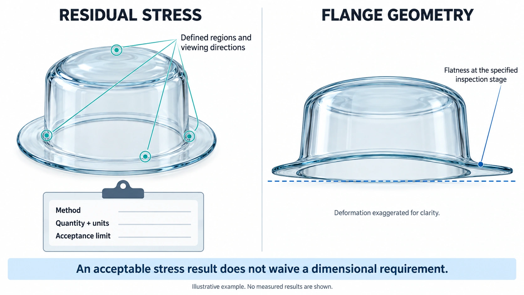
Consider an illustrative flanged lighting cover whose residual-stress result meets the specified criterion but whose flange flatness is outside the drawing tolerance. This is a troubleshooting example, not a production case report or a measured result.
| Observation | Relevant records | Verification before deciding the cause |
|---|---|---|
| Stress passes; flange flatness fails | Inspection stage, datums, temperature condition and measurement method | Confirm the flatness result and stress coverage refer to the same required product state. |
| Distortion appears associated with an annealing position | Load map, supports and actual thermal history | Compare traceable articles across positions; check support condition and repeatability. |
| A thermal or support change is proposed | Forming history and baseline stress, shape and surface results | Trial the change and reassess all affected requirements together. |
An acceptable stress result does not waive the dimensional requirement. Contain the affected production as defined by the control plan while the cause and disposition are assessed.
Where practical, compare identifiable articles before and after the suspected operation under suitable measurement conditions. Do not assume annealing caused the deviation solely because it was first detected after cooling.
Recheck After Finishing or Thermal Rework
Define the checks to repeat after operations that can change an accepted blank. Material removal may alter stress balance, expose damage or allow dimensional movement; later heating can affect shape, coatings and an intentional strengthening profile.
| Operation | Characteristics to review |
|---|---|
| Grinding, polishing, drilling or thread finishing | Final dimensions, profile, local damage, surface condition and stress-related effects where relevant |
| Etching, sandblasting, coating or decoration | Surface or coating quality, optical function and performance affected by treatment or heating |
| Thermal or chemical strengthening | Treatment-specific stress characteristics, geometry and application performance |
| Bonding or assembly | Alignment, mounting stress, fit and final function |
| Reannealing or other thermal rework | Suitability of the route and all affected dimensional, visual, stress and functional requirements |
Reannealing is an assessed rework option, not a default repair. Confirm its compatibility with the material, geometry, coatings and strengthening state. Existing cracks and inclusions are not removed by annealing.
Identify reworked articles, retain the actual route and repeat the affected checks before an authorised release decision. Confirm the permitted order of finishing and strengthening rather than relying on an earlier annealing report.
Contain Excursions and Document Release
Define the lot and sampling plan around the variation that matters: material lot, mould or station, lehr lane, furnace position, loading arrangement, start-up and restart conditions. Samples selected only for easy access may miss an affected part of production.
Connect an abnormal event to a product decision
- Identify and contain: mark the potentially affected batch or production interval, including relevant lanes or positions. Account for articles already unloaded or moved to later operations.
- Review the evidence: compare actual thermal history, transfer conditions and loading with the validated process. Determine what can be established and what remains unknown.
- Decide the assessment or rework: define additional inspection, testing or an assessed rework route. Do not repeatedly resample until a favourable result is obtained; use the agreed failure-response plan.
- Verify and authorise: review all required results, record deviations or rework, and document the disposition before release.
Restoring a controller setting does not release the affected glass. Likewise, passing samples support a lot decision under the agreed plan; they do not prove that every unmeasured article is identical.
Retain a usable acceptance record
Connect product identity and drawing revision with material, forming traceability, equipment and programme revision, loading configuration, actual thermal history and inspection stage. Retain sample selection, instrument and method, locations, orientations, supports, results, units, limits and the release decision.
Use suitable calibration, reference checks and repeatability assessments. Define how measurement uncertainty affects decisions near an acceptance limit.
Keep process settings, alarm limits and product acceptance criteria distinct. A completed programme is process evidence; release depends on the required product results and documented disposition.
For a custom pressed-glass project, provide BO-Glass with the drawing or 3D model, application, material, critical surfaces and expected quantity. Include the required inspection stage and residual-stress, dimensional, optical and thermal criteria so that annealing, inspection and quotation scope can be reviewed with the forming route.
Contact Us
Your feedback fuels our growth, and your questions drive our solutions.
We value your feedback, inquiries, and suggestions. Please feel free to get in touch with us
General inquiries
Please contact us via sales@bo-glass.com, and we will reply to you as soon as possible.
Interested to work with us
Drop your resume at info@bo-glass.com
and we will get back to you shortly.
We uses the contact information you provide to us to contact you about our relevent content, products, and services.