
Molten Glass Pressing Process Control
A practical guide to coordinating gob delivery, plunger motion, contact time and production checks for directly pressed glass components.
A correctly weighed gob can still produce uneven walls or incomplete features if loading, motion and heat transfer are poorly coordinated. Process control links those events to filling, release and the required dimensions, appearance and residual stress after annealing and finishing.
Define the Cycle and Start-Up Conditions
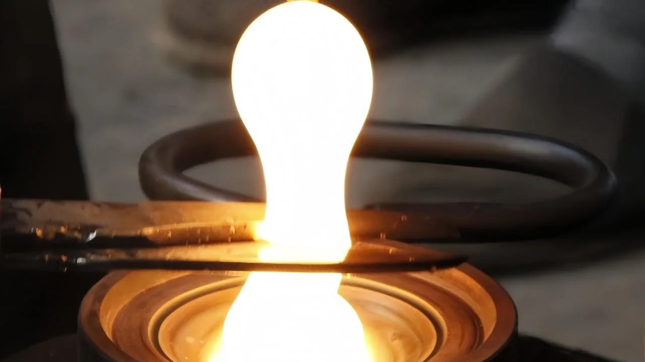
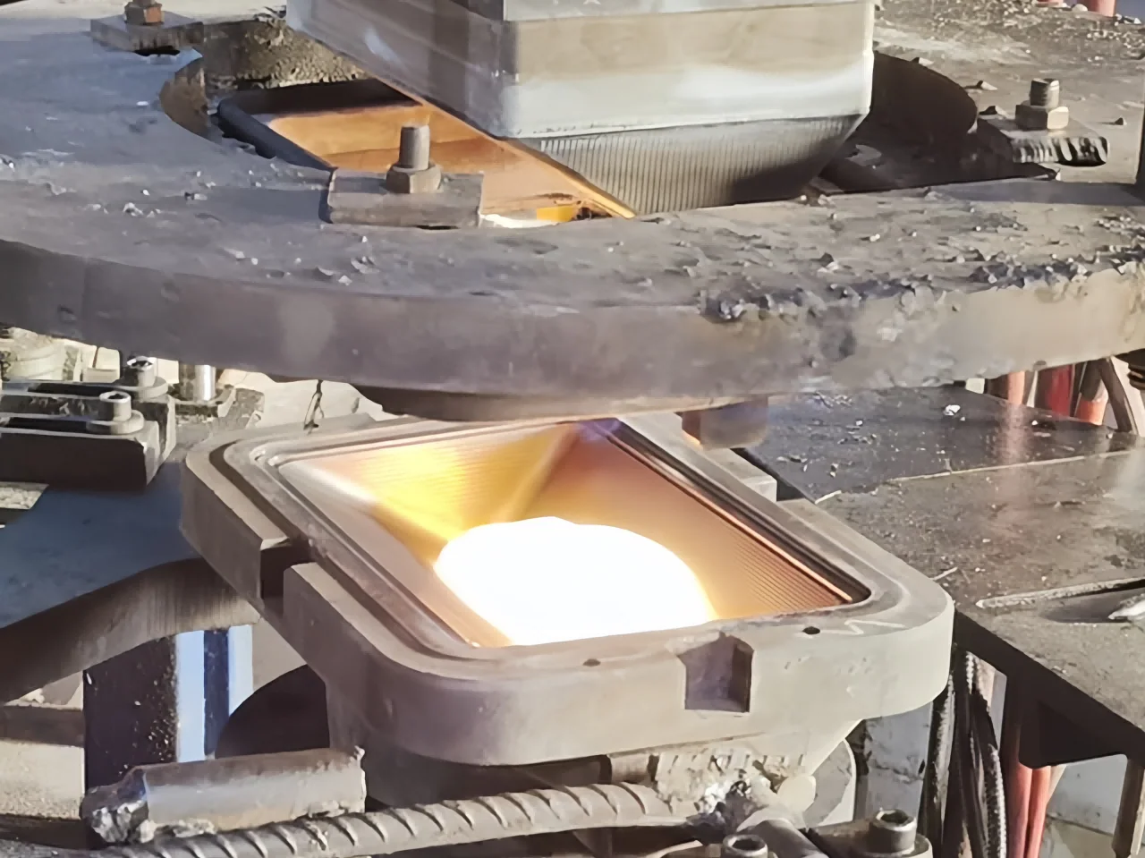
Describe the cycle through observable events, then identify which transitions the machine controls and which depend on an operator. A recipe is usable only with the specified glass, tooling and operating conditions.
| Cycle stage | Transition or confirmation to define |
|---|---|
| Prepare and load | Tool readiness, clear loading path and gob arrival |
| Approach and form | First contact, actual motion and the condition that starts dwell |
| Dwell and withdraw | Maintained forming condition, dwell completion and separation |
| Remove and transfer | Tool clearance, component support and downstream placement |
| Prepare for the next charge | Empty mould, required tool condition and station availability |
The sequence depends on the tooling and machine. Automated equipment may coordinate feeding, pressing and handling through to the annealing lehr; WALTEC's pressing equipment illustrates such arrangements. Describe only the functions present on the actual line.
Confirm readiness before loading
- Glass and tooling: Verify glass identity, the approved mould, plunger, ring and insert configuration, alignment and working clearances.
- Thermal systems and surfaces: Check heating and cooling functions, forming-surface condition and clear vent paths.
- Delivery and motion: Confirm the loading path and position, press motion references and equipment interlocks.
- Removal and downstream equipment: Check take-out support and clearances, transfer equipment and annealing readiness.
Tool preheating and start-up checks need defined measurement locations. During repeated cycles, thermal readiness means a sufficiently repeatable temperature pattern at the specified events, rather than equal temperature everywhere.
For established production, compare readings at the same locations and cycle events with the approved production baseline. The control plan should specify the observation period, permitted variation and conditions for beginning sample collection. Stable gob mass alone does not establish stable temperature or delivery.
Keep start-up material identifiable
Link samples to time, station, tooling and operating condition. Check filling, release and appearance, then complete the required cold inspection after annealing or finishing. Define the evidence needed to authorise routine production and retain a pending status for material awaiting those results.
Synchronise Gob Delivery and Initial Contact
Coordinate loading with mould availability and plunger clearance. Record arrival relative to first contact: the gob can spread and lose heat during the intervening period, changing the initial flow path.
On automated equipment, distinguish shear actuation, glass separation, delivery-path entry, mould arrival and first plunger contact. Use a common timing reference. For timing expressed as machine angles or cycle percentages, retain the associated cycle duration; changing speed can change elapsed time at the same timing setting.
On rotary equipment, distinguish the indexing interval from the interval between successive charges entering the same mould. Define responses to missing, late, misdirected or double charges, including the affected station and production interval.
Check loading and the first contact
Observe lateral offset, orientation, shape, folding and contact with the mould wall or ring. The approved loading location may be central or deliberately offset, depending on geometry and verified results.
The approach profile should avoid uncontrolled impact or unintended displacement. Where signals are available, compare force and position around contact. A changed contact point may reflect gob shape, mass, placement, tooling position or a shifted measurement reference; a force rise alone cannot distinguish these causes.
Map filling and thickness at defined locations and orientations: rim extremities, thin walls, rib tips, recesses and transitions. Confirm a continuous air escape route in the assembled tool. A forming-related air pocket and a bubble already in the incoming glass require different investigations. Relate observations to the defect location before adjusting the press.
Control Plunger Motion and Forming Load
Identify approach, initial forming, further penetration, final forming and withdrawal in the recipe. Record commanded settings alongside the actual response where the equipment supports that measurement.
| Control arrangement | Primary control | Behaviour to review |
|---|---|---|
| Position or speed control | Movement along a specified profile | Actual motion, required load and available travel |
| Force control | Measured or estimated forming force | Position, movement rate and travel limits |
| Staged control | Different variables at different stages | Switching conditions, overshoot, force peaks and delays |
These capabilities are machine-specific. A pressure regulator and mechanical stop do not establish independent closed-loop control of force and position.
Define the displacement reference
State where movement is measured and how zero is established. An actuator encoder measures drive movement, which may differ from the working gap because of tool expansion, machine deflection, mounting condition and clearances.
Correlate final position with measured wall thickness and geometry at the agreed inspection stage. Meeting a position setpoint alone does not demonstrate an acceptable component.
Distinguish pressure, force and interface loading
Machine pressure is a hydraulic or pneumatic reading at a specified location. Forming force is the load transmitted through the mechanism. Contact pressure is the local loading at the glass–tool interface as contact and glass distribution evolve.
An actuator-force estimate needs the relevant chamber pressures and effective piston areas, with allowance for the mechanical arrangement, friction and acceleration. Electric presses may use a load sensor or a drive-based estimate; identify the signal source. Force divided by a stated area is a nominal average, not a map of cavity pressure.
Compare load histories at common cycle events or plunger positions: onset, rate of rise, dwell behaviour and unloading. Retain a representative accepted trace where available, together with its glass, tool and thermal conditions. Investigate poor filling against gob condition, available mass, venting and tool temperature before deciding whether more force is appropriate.
Define Dwell and Glass–Tool Contact Times
Define dwell by the condition maintained and the events that start and end it. Holding force, holding position and waiting after an approach command describe different machine states.
Use event-based time definitions
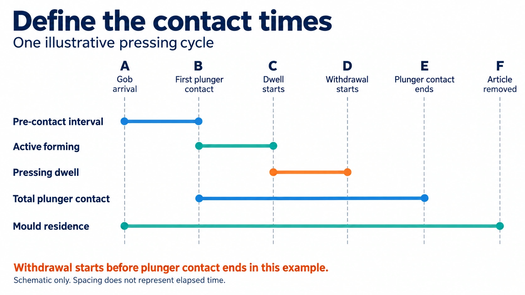
The gob contacts the mould before it contacts the plunger. The article can remain in the mould after plunger separation. Record the pre-contact interval, active forming interval, pressing dwell, total plunger contact and mould residence separately.
In the illustrated sequence, dwell ends as withdrawal begins, while plunger contact ends later. Actual separation, a withdrawal command and reaching the clearance position are distinct events. Define which event is detected directly and which is inferred from a qualified signal or motion condition.
Select dwell with filling, feature replication, heat extraction, shape retention and release in view. Assess changes over repeated cycles because a longer contact interval also changes tool heating and the article's temperature distribution.
Stress relaxation during forming does not establish acceptable residual stress in the finished component. Subsequent cooling, annealing and the specified inspection remain part of acceptance.
Coordinate Thermal Conditions and Production Rate
Gob condition, tool temperature and timing interact. Changing one can alter forming resistance, surface development and release even when the remaining setpoints stay unchanged.
Use material data and defined measurement events
Glass viscosity depends strongly on temperature and composition. Use applicable data for the selected glass; a catalogue transformation temperature does not define the pressing recipe. SCHOTT TIE-31 explains viscosity and thermal reference points for optical glasses and provides background principles, not production settings for every glass family.
For each temperature record, state location, method and cycle event. An embedded sensor does not directly measure the instantaneous working-surface temperature. Infrared readings also depend on wavelength, viewing arrangement, surface condition and the glass's transmission and emission behaviour. Label estimates and retain the measurement basis when comparing runs.
Recheck the thermal pattern after a rate change
Review contact duration, cooling operation and the interval between charges to each mould. Observe the response until the defined stabilisation condition is reached, then inspect representative articles. A few acceptable pieces immediately after adjustment do not demonstrate sustained performance.
Keep station results identifiable: averaging temperatures or product measurements across moulds can conceal a persistent local difference. Review changes in output with transfer capacity and lehr loading as well as the press itself.
Control Release and Transfer to Annealing
Release and handling must preserve the article while its shape remains sensitive to support and thermal conditions. Coordinate plunger withdrawal, ring movement, mould opening and removal around the actual retention features.
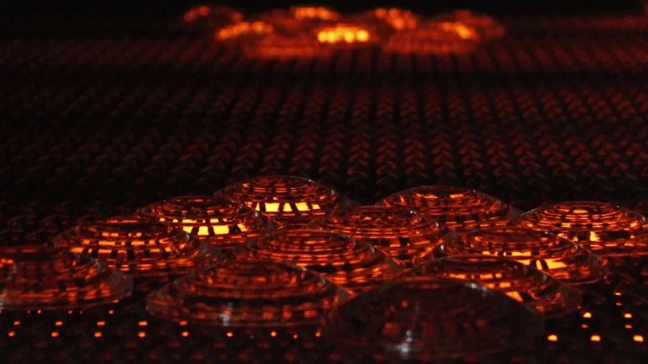
Define the dwell-ending condition, unloading sequence, withdrawal motion, required clearances and component support. Confirm that the mould is empty before the next charge. Where available, relate withdrawal-load changes to observations of sticking, dragging, catching or distortion.
Investigate release against tool temperature, surface condition, lubricant application where used, wear, draft and alignment. Recheck appearance, feature replication and subsequent dimensions after a correction.
For transfer, document gripping or supporting locations, contact materials, handling force or adjustment method, orientation, elapsed time and the response to downstream delays. Include fire polishing or other hot operations in the recorded route where applicable.
Uneven cooling and restraint influence thermal stress; SCHOTT TIE-32 explains the general relationships for optical glass. Establish the actual transfer conditions and annealing acceptance for the selected product. Detailed annealing and final-quality checks belong in the accompanying thermal and inspection guide.
Monitor the Process and Respond to Deviations
Choose signals and inspection frequency according to the product risks and available equipment. Link measurements to a common time reference, material identity, recipe revision and mould or station. Manual checks should retain the same traceability as automatic records.
| Control item | When and what to record | Initial checks after a deviation |
|---|---|---|
| Gob mass and loading | Defined sampling stage; mass, arrival and loading position | Confirm the measurement, supply condition and affected outlet or station |
| Temperature and cooling | Defined locations at matched cycle events; circuit interruptions | Confirm the reading, circuit state and recent timing or rate changes |
| Motion and forming load | Actual response through approach, forming and dwell, where available | Check references, switching events, loading and possible interference |
| Dwell and residence | Named start and end events and actual durations | Locate delayed or missing events and compare glass–tool contact intervals |
| Release and transfer | Separation, removal and downstream placement; interruptions | Check support, clearances, release behaviour and downstream readiness |
| Product characteristics | Agreed locations, orientation and inspection stage | Identify the pattern by station and time; retain samples and their process records |
These checks guide investigation; they are not automatic diagnoses or permission to operate outside an approved range. Put numerical criteria, sampling frequency, intervention authority and restart checks in the product-specific control plan.
Keep settings, ranges and limits distinct
| Term | Purpose |
|---|---|
| Target setting | Intended normal operating condition |
| Validated process range | Parameter combinations supported by acceptable product evidence |
| Alarm or stop condition | Defined trigger for intervention or interruption |
| Product acceptance limit | Requirement for the component at the stated inspection stage |
| Statistical control limit, where used | Boundary calculated from process behaviour for detecting change; distinct from a product specification |
Separate process recovery from product disposition
- Identify the affected time interval, stations and quantity. Account for detection delays and downstream work in progress; the interval may start before the alarm.
- Mark or segregate material awaiting a decision and preserve the associated records and samples.
- Investigate and correct the deviation, recording changes and their supporting evidence.
- Verify process readiness and the required results from restart samples before authorising resumed routine production.
- Separately evaluate the affected material against the applicable acceptance criteria. Record its disposition and the responsible decision-maker; conforming restart samples alone do not release earlier production.
Uneven Wall Thickness with Acceptable Part Mass
In this example, part mass is measured after annealing and before grinding, polishing or other material-removing operations. Assume the sampled parts meet the mass limits for that stage, while thickness measurements repeatedly show a thin region on one side. These results alone establish neither statistical stability nor incoming gob mass. This is an illustrative investigation plan, not a reported production result or a universal adjustment sequence.
First confirm the measurement method, part orientation and specified inspection stage. Link samples to the same tooling reference so that "the thin side" has a consistent meaning.
| Observation to compare | Records or conditions to examine | Verification approach |
|---|---|---|
| Thin region stays at the same tooling location | Alignment, working gap, vent condition and local thermal observations | Inspect the implicated area and compare station-specific thickness maps |
| Thin region changes with the loading position | Gob placement, shape and arrival-to-contact interval | Compare identified loading observations with the corresponding parts |
| Thickness drifts during start-up or after a rate change | Tool-temperature pattern, contact intervals and cooling state | Sample after the defined stabilisation condition and compare with the baseline |
| Similar forming observations give different final geometry | Release support, transfer delays, annealing and finishing history | Compare traceable samples at the agreed intermediate and final inspection stages |
Treat each relationship as a hypothesis. For diagnostic adjustments, change a documented factor while holding the others as consistent as practicable; planned experiments may intentionally vary combinations. Record actual conditions and allow the defined stabilisation before sampling.
An accepted correction must satisfy the full relevant specification, including other wall locations, appearance, seating geometry and residual stress where required. Improving one thickness reading alone is insufficient.
Validate Parameter Combinations and Repeatability
Establish combinations that produce acceptable components under the intended operating conditions. A dwell time demonstrated with one gob condition and cooling arrangement may behave differently after either changes.
Several parameters individually lying within their stated ranges does not establish that every combination has been validated.
Define the factors and combinations to evaluate, stabilisation before sampling, represented material lots and stations, inspection methods, criteria and sample-to-process traceability. Structured trials can distinguish individual effects from interactions; NIST's factorial-design guidance explains the method.
Include relevant start-ups, sustained operation, tooling positions, maintenance states and representative restarts. Evaluate dimensions, wall distribution, appearance, residual stress and application-specific performance at the required delivery state, including finishing or coating when specified.
Statistical stability and specification compliance require separate assessment. Capability analysis needs suitable data, a reliable measurement system and appropriate statistical assumptions. A result for one dimension cannot represent all functional requirements. See NIST's process-capability guidance.
Control Recipes, Changes and Restart Approval
Keep the evidence supporting the approved recipe alongside its machine settings. Record actual revisions and the authority to change or release them.
| Recipe record | Information to retain |
|---|---|
| Product and material | Drawing revision, glass identity, delivery state and acceptance requirements |
| Tooling | Mould, plunger, ring and insert identities; approved station allocation |
| Delivery and pressing | Gob requirements, loading, timing, motion stages, control modes and transition events |
| Thermal and handling conditions | Measurement references, cooling, contact intervals, withdrawal, support and transfer |
| Control and acceptance plan | Targets, validated combinations, alarms, sampling, inspection and disposition authority |
| Change and release history | Revision, reason, trial evidence, restrictions and approval |
A glass change may affect flow and thermal requirements; tool repair can alter geometry, surface condition or venting; cooling maintenance can change heat extraction. Define verification according to the change's effects. Reloading previous settings does not confirm that previous operating conditions have been restored.
For a short interruption, extended shutdown or tool replacement, review the cause and duration, tool condition, glass delivery stability and downstream readiness. Record the checks, restart samples, outstanding results and decision to resume routine production. Keep the disposition of any earlier affected material separate.
For a custom molten glass pressing review or quotation, provide BO-Glass with your drawing or 3D model, application, glass requirements, critical dimensions, surface expectations, delivery condition and production quantity. For an existing quality issue, include marked defect locations, sample identification and relevant process records. These inputs help define the tooling, development trials and inspection scope for the proposed supply.
Contact Us
Your feedback fuels our growth, and your questions drive our solutions.
We value your feedback, inquiries, and suggestions. Please feel free to get in touch with us
General inquiries
Please contact us via sales@bo-glass.com, and we will reply to you as soon as possible.
Interested to work with us
Drop your resume at info@bo-glass.com
and we will get back to you shortly.
We uses the contact information you provide to us to contact you about our relevent content, products, and services.