
Mould Design and Thermal Management for Molten Glass Pressing
A practical guide to mould construction, venting, cooling and tool approval for molten glass pressing.
The cavity, plunger and supporting parts must distribute molten glass, remove heat and release the article while preserving its functional surfaces. This guide links those tasks to the tool drawings, trial evidence and maintenance criteria that engineers and purchasing teams need to agree before production.
Define the Mould Set and Machine Interfaces
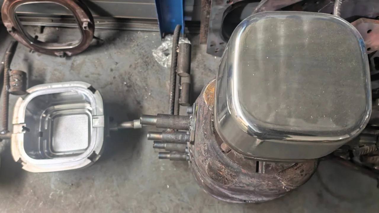
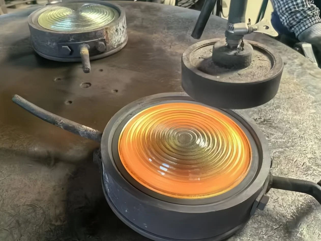
Start by identifying which tool forms each product surface and how the complete set fits the intended press. A shallow dish, a ribbed lighting cover and a threaded article can require different opening and support arrangements.
| Element | Function to define | Required design information |
|---|---|---|
| Cavity body or insert | Receives the charge and forms selected external surfaces | Profile, mounting references, material, vent and cooling features |
| Plunger | Distributes glass and forms the opposing surface | Profile, operating position, guidance, thermal control and withdrawal path |
| Ring or opening sections | Form boundaries and allow release where required | Seating, closure, parting locations and movement sequence |
| Holders and guides | Maintain the relationship between forming parts | Machine interfaces, support, adjustment and component identification |
WALTEC lists block, hinged and tulip mould systems for its pressing tables. These are equipment examples; the chosen arrangement still needs to suit the particular article and machine. WALTEC: Glass Production Lines
Document the assembled configuration
The assembly drawing should show a common axis or locating references, seating planes, orientation features and the approved combinations of inserts, rings and plungers. Identify the equipment mounting dimensions, available stroke, access for loading and take-out, and connections needed for cooling.
Give replaceable parts traceable identifiers and specify how their location will be checked after installation. Matched components should not be mixed simply because each passes its individual inspection. Keep identification away from glass-contact surfaces and retain the drawing revision with the assembled set.
Design the Forming Space and Release Sequence
Develop cavity and plunger surfaces from the finished-component requirements. Keep the nominal product geometry separate from the tool compensation, finishing stock and machine setup used to achieve it.
Check filling throughout the stroke
Review the changing forming gap as the plunger enters, including narrow sections, deep patterns, thin terminal edges and the transition from a thick rim to a thinner wall. A feature that exists in the final tool space may still receive glass late in the stroke.
Define how the final pressing position is established and checked. Relate that position to the intended wall distribution while allowing for the actual gob condition, tool movement and thermal response. A machine displacement reading can include compliance outside the forming surfaces; it is not, by itself, a wall-thickness measurement.
Cold dimensions also need to be assessed against tool expansion and the glass dimensions after annealing and any finishing. Retain compensation changes as controlled revisions, supported by measurements from identified trials.
Resolve withdrawal, parting and alignment together
Mark the forming and withdrawal directions on the drawing. Review draft, internal shoulders, threads and other undercuts against the proposed opening sequence. Specify the required relief or opening sections for the geometry; draft values need to be agreed for the actual glass, surface and release conditions.
Place parting interfaces with regard to optical areas, sealing faces, locating diameters and thread engagement. Define acceptable interface marks, steps or excess glass on the product drawing. Check closure support, plunger-to-cavity alignment and rotational orientation under representative operating conditions.
Distinguish guide clearance, forming gap and vent opening: they serve different functions. Confirm that the hot article remains supported while the plunger, rings and mould sections move, and that take-out does not load a vulnerable rim or patterned surface.
Select Tool Materials by Component
Select the material and treatment condition for each tool component, considering heat transfer, thermal expansion, strength at temperature, thermal fatigue, wear, oxidation and repairability. The cavity and plunger need not use the same alloy.
Gillinder describes ductile iron for most of its moulds, with A-2 tool steel or stainless steel for some requirements. This is a manufacturer-specific example, not a universal material specification. Gillinder: Mould Making for Pressed Glass
| Component | Selection considerations | Evidence to review |
|---|---|---|
| Cavity body | Heat removal, section stability and manufacture of the required profile | Material grade, condition and dimensions linked to trial results |
| Plunger | Glass contact, guidance, withdrawal and cooling arrangement | Surface condition, operating fit and release behaviour |
| Ring or replaceable insert | Local wear, seating and thermal movement | Installed position, interface condition and replacement checks |
| Repaired or coated region | Compatibility with the base tool and permitted material removal | Repair specification and verification of affected features |
Treat substitutions as changes to the process
An alloy substitution can change the tool's temperature distribution and dimensional response even when the cold geometry is unchanged. Review fit, cooling, release and component quality before approving it. Record the actual grade and treatment condition rather than descriptions such as “heat-resistant metal”.
Provide a Complete Air Escape Path
Venting should follow the expected sequence of glass contact and filling. Identify where air could become enclosed as the gob spreads, especially around deep patterns, perimeter regions and surfaces contacted early in the stroke.
Trace the path to its outlet
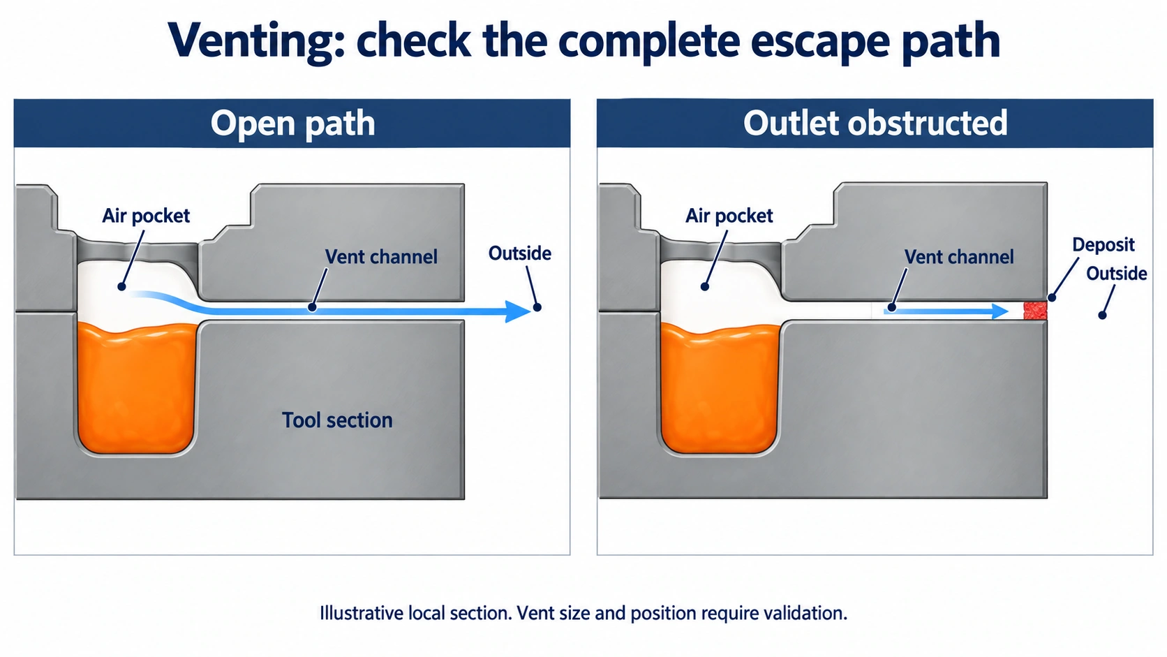
For each intended vent, follow the route from the potential air pocket through the groove, hole or controlled interface to a usable outlet. Review the assembled tool: a passage visible in an individual insert may be covered by its holder, mating component or deposits.
The drawing should identify the inlet, passage, outlet and the features that control their assembled relationship. Provide access for inspection and cleaning, including after the tool has been refitted.
Balance air escape with mark control
Define vent locations relative to optical, sealing and appearance zones. Vent geometry must allow the intended air escape while limiting glass intrusion and unacceptable marks. Its dimensions require development for the particular geometry, glass condition and cycle.
Include vents in the inspection after polishing, repair or component replacement. When investigating local filling defects, compare the vent condition with gob placement and filling sequence. Distinguish a cavity air issue from bubbles already present in the incoming glass.
Control Forming Surfaces and Release Treatments
Specify surface condition by function. A forming surface may need controls for overall profile, waviness, roughness, intentional texture and isolated defects; a polished appearance does not establish all of these characteristics.
Protect geometry during finishing
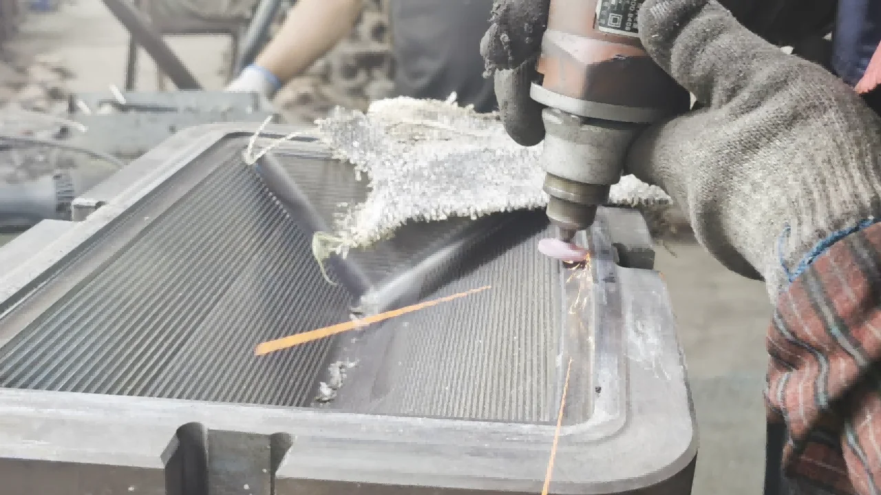
For a ribbed or prismatic cover, identify pitch, depth, flank geometry and edge radii that finishing must preserve. Record permitted material removal and inspect the affected features after resurfacing. Apply the same discipline to narrow seating faces and parting edges.
Where roughness is specified, identify the parameter, measurement area or profile length, and relevant filtering. Separately identify surfaces that form the delivered component and surfaces that generate stock for later grinding or polishing.
Specify the treatment and its application
Machine lubrication, gob-delivery treatments and glass-contact release products have different duties. FUCHS lists these as distinct product categories; suitability must be established for the actual application. FUCHS: VITROLIS Glass Industry Products
For an applied mould treatment, record product identity, treated surfaces, preparation, coverage, conditioning and reapplication criteria. Evaluate release together with deposits, transferred marks and subsequent cleaning or coating requirements.
For a durable coating, define coverage, relevant thickness and adhesion requirements, and acceptable service condition. Repair or recoating needs checks for changes to form and fit. Neither a release product nor a coating should be expected to resolve an incompatible withdrawal path or misaligned assembly.
Establish the Thermal Cycle and Start-Up Conditions
Preheating establishes a starting condition. Production then creates repeated heat input from glass contact and heat removal through the tool, cooling system and surroundings. A repeatable thermal cycle can be the appropriate target; a constant temperature is not required at every location.
Connect thermal checks to cycle events
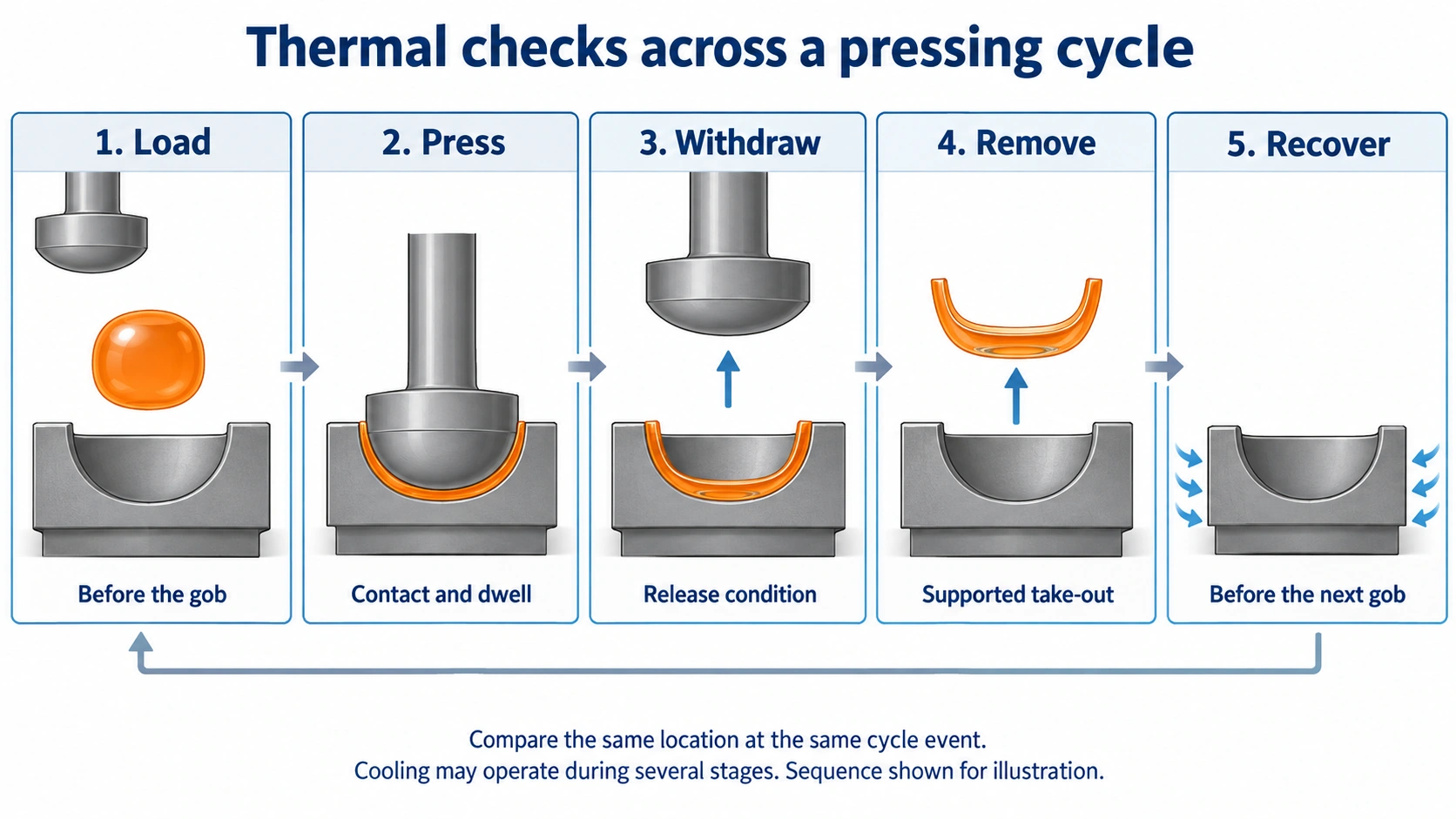
Define the events used to compare conditions: before loading, during pressing contact, at plunger withdrawal, during article removal and before the next gob. Record contact time, relevant machine timing and interruptions alongside temperatures. Cooling may operate during several of these stages.
Assess changes to contact time, withdrawal timing and cooling together with filling, shape retention and release. The mould, plunger and ring have different contact histories; one temperature reading cannot describe the complete set.
Release production using defined evidence
Before start-up, confirm the installed tool identities, cleanliness, surface treatment, movement and cooling connections. Use the approved equipment and tool-heating procedure, with temperature checks at defined locations. Heating time is useful only when its relationship to the required tool condition has been established.
Keep start-up components identifiable while the tool approaches its production condition. Define the temperature observations and component results needed to release production. Restart criteria should address interruptions, extended idle periods, tool changes and treatment renewal rather than assuming every restart resembles an uninterrupted cycle.
Design Cooling and Temperature Measurement Together
Plan cooling around the heat entering each region, the conduction path through the tool and the support needed behind the forming surface. A thick rim, a thin optical section and a massive insert can have different requirements.
Verify delivery to the intended region
Identify cooling locations or passages, the distance from the forming surface, flow distribution, outlets and access for cleaning. Consider mould, plunger and ring circuits separately where the equipment permits independent control. The cooling medium must suit the designed equipment; liquid-cooled systems require their specified containment and integrity checks.
A supply setting does not demonstrate the flow reaching every passage. Use appropriate flow, pressure, temperature or system checks to identify restrictions and imbalances. Recheck the response after cleaning, repair or replacement.
Removing heat can assist shape retention while making late-filling regions harder to form. Evaluate cooling changes against the complete component, including pattern replication, release and dimensions at the specified delivery state.
Make readings comparable
| Record with each thermal comparison | Detail to define |
|---|---|
| Location and event | Component, sensor position and stage of the cycle |
| Measurement method | Contact, embedded or infrared method; instrument settings and response |
| Target condition | Treatment, oxidation, deposits and infrared viewing arrangement where relevant |
| Production state | Start-up, established operation, interruption or restart; associated timing and cooling settings |
An embedded sensor reports its local temperature with a response influenced by its installation. An infrared reading depends on the target surface, viewing conditions and reflected radiation. Keep inferred surface temperatures and model outputs identifiable as such.
Compare the same location at the same cycle event before interpreting a trend. Different regions need not share a temperature; their qualified behaviour must support acceptable parts.
Maintain Tool Condition and Control Repairs
Use the function of each feature to set inspection priorities. Worn prism edges, a damaged seating face or a restricted cooling passage can matter before a general cavity dimension moves outside its limit.
Connect observations with checks
The following observations guide an investigation; none identifies a unique cause.
| Observation | Checks to bring together |
|---|---|
| Uneven wall distribution | Alignment, seating, gob location, forming position and thermal conditions |
| Repeated local filling loss | Vent continuity, feature condition, contact sequence and gob condition |
| Drag or sticking marks | Withdrawal path, surface deposits, treatment and release timing |
| Growing parting step | Closure, matched components, seating wear and thermal movement |
| Change after maintenance | Modified geometry, vent paths, cooling delivery and restored setup |
Record cavity or tool identity with defect locations and measurement trends. This helps distinguish a local tool condition from a change affecting all cavities.
Define the return-to-service decision
Separate cleaning from operations that remove or rebuild material. Protect patterned surfaces, parting edges, vents, coatings and locating references. After polishing, insert replacement, rebuilding or recoating, inspect the affected geometry and interfaces; use a production trial where their function or thermal response may have changed.
Track wear, pitting, adhesion, thermal-fatigue cracks, oxidation and circuit condition. Use cycle counts and service dates to organise inspection, with acceptance based on function and condition. Replace or refer the tool for engineering disposition when damage exceeds the repair allowance, recurring defects remain after repair, or structural or cooling integrity cannot be restored. Preserve identification and protected surfaces during storage.
Worked Example: A Lighting Cover with a Heavy Rim
Consider a directly pressed lighting cover with a thin ribbed transmitting region and a thicker mounting rim. The following is an illustrative review plan. Dimensions, acceptance limits and production settings must come from the project specification and trials.
Link product requirements to tooling and checks
| Product requirement | Tooling decision to document | Trial verification |
|---|---|---|
| Defined ribbed transmitting region | Identify the forming surfaces and preserve rib pitch, depth and flank geometry | Check filling and pattern geometry using the agreed inspection method |
| Usable mounting rim and seating face | Mark seating references, finishing stock and permitted parting marks | Measure seating dimensions and confirm the specified assembly fit at the agreed delivery state |
| Controlled wall transition | Review the forming gap throughout the stroke and trace air escape to an open outlet | Map wall distribution and local filling against gob condition and thermal observations |
| Shape retained during removal | Define withdrawal directions, support, timing and relevant cooling regions | Inspect distortion and release marks; relate observations to the recorded cycle events |
Use trials to resolve the uncertainty
Establish a baseline with identified glass, gob condition and tool configuration. Record temperatures at defined locations in the rim and transmitting regions at consistent cycle events. Different local thermal conditions may be appropriate; evaluate their effect on the whole component.
If the transmitting region fills poorly, investigate its filling sequence, air escape and local thermal condition alongside the incoming gob. If removal distorts the rim, examine release timing and support as well as cooling. Record deliberate changes and compare their effect on the entire part.
Approve the seating dimensions and optical features at the specified state after annealing and any required finishing. Retain representative accepted samples and the tool, treatment and cycle records that produced them.
Qualify the Tool and Agree the Delivery Scope
Tool inspection establishes the mould set's measured condition. Production trials establish how that set performs with the selected glass, feeding arrangement and thermal cycle. Approval should connect these two kinds of evidence.
Define the acceptance package
Before trials, agree the acceptance basis and name the reviewer for each function below. The project documents should establish the allocation of responsibilities and approval authority.
| Record | Evidence and acceptance basis | Reviewer to identify |
|---|---|---|
| Tool definition | Approved drawing revisions, specified materials and treatments, matched-component list | Design approver |
| Assembly inspection | Measured geometry and clearances against drawing limits; alignment, vent and cooling checks using agreed methods | Tooling or inspection lead |
| Trial record | Identified glass, gob and tool configuration; setup, timing and thermal records required by the trial plan | Process lead |
| Component results | Measurements, appearance and assembly checks against the agreed specification, methods and delivery state; cavity and sample identification | Quality reviewer |
| Production release | Accepted configuration, resolved deviations, restrictions and the production inspection plan | Designated production approver |
| Maintenance plan | Condition limits, permitted repairs and checks required before return to service | Tooling or maintenance lead |
Record the reviewer, date, decision and any open conditions. Where customer approval is required, retain it alongside the supplier's internal release record.
Specify whether acceptance applies after pressing and annealing, after finishing or after coating. Include start-up and representative continued-production results where needed to establish repeatability. Link each sample to its tool and trial conditions.
Agree ownership, storage, maintenance responsibility, replacement arrangements and approval of design changes. For a supplied existing mould, review its documentation, condition and machine compatibility before committing to reuse. Tooling cost and lead time should reflect the required components, development trials, inspection and maintenance scope.
Request a mould and tooling review
Send BO-Glass the component drawing, glass specification, critical optical and assembly requirements, expected quantities and required delivery state. For an existing tool, include available drawings, photographs, maintenance records and examples of the product issue.
These inputs support a review of the mould arrangement, thermal management, validation work and quotation scope for the pressed glass component.
Contact Us
Your feedback fuels our growth, and your questions drive our solutions.
We value your feedback, inquiries, and suggestions. Please feel free to get in touch with us
General inquiries
Please contact us via sales@bo-glass.com, and we will reply to you as soon as possible.
Interested to work with us
Drop your resume at info@bo-glass.com
and we will get back to you shortly.
We uses the contact information you provide to us to contact you about our relevent content, products, and services.