
Glass Selection, Melt Conditioning and Gob Control for Molten Glass Pressing
A practical guide to specifying glass, controlling melt quality and delivering consistent gobs to the mould.
A pressed glass component depends on both the selected material and the condition in which it reaches the press. Composition establishes the available properties; melting, conditioning and delivery influence how consistently those properties and the required geometry can be achieved.
A gob is the portion of molten glass supplied for a forming cycle. Correct mass alone does not ensure consistent filling: shape, thermal condition, transfer time and loading position also matter.
Selecting Glass for the Application and Production Route
Start with the finished component's function. A lighting cover, decorative bowl and industrial window may have different requirements for transmission, colour, thermal expansion, chemical durability and mounting conditions.
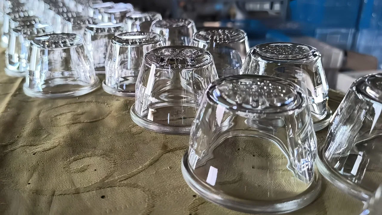
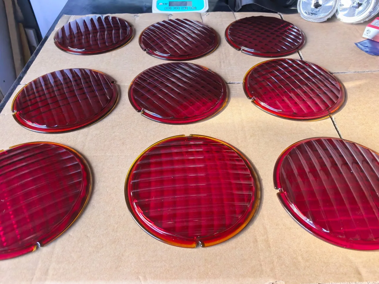
Identify the operating temperatures and temperature changes, chemical exposure, optical function and planned grinding, polishing, coating or strengthening. These requirements narrow the material candidates before production trials begin.
Compare candidates against the actual requirement
The table identifies evaluation routes, rather than interchangeable materials. Soda-lime and borosilicate describe composition families; optical and filter glass describe performance or application categories that can overlap those families. Availability and suitability for direct pressing require confirmation for the actual grade.
| Candidate | When to include it in the review | Main questions to resolve | Useful information to provide |
|---|---|---|---|
| Soda-lime glass | General pressed articles where appearance, durability and production economics drive selection | Does the grade meet the thermal, optical and finishing requirements? | Service conditions, appearance criteria and quantities |
| Borosilicate glass | Applications requiring the expansion or chemical properties of a suitable borosilicate composition | Can the available grade be melted, conditioned and pressed with the intended tooling? | Grade or expansion requirement, temperature interval and chemical exposure |
| Optical or filter glass | Defined refractive properties, dispersion or spectral transmission | Can the required properties and internal quality be retained through the proposed thermal history? | Optical specification, path length and acceptance method |
| Other speciality glass | A required property is unavailable from the initial candidates | Is there a suitable supply form and a feasible development route? | The essential property, acceptable alternatives and supply expectations |
Specify the grade, supply form and finish
Terms such as “high-transmission glass” do not establish a material specification. Identify the manufacturer and grade where fixed, or the properties that permitted alternatives must preserve.
Record whether the manufacturing chain receives batch ingredients, previously melted glass or controlled cullet for remelting. An incoming certificate applies to the supplied material; subsequent remelting and forming need appropriate controls and verification.
Specify bulk colour, opacity and surface finish separately. Coloured coatings and frosting do not identify the underlying composition. Assign responsibility for material supply, melting, conditioning and pressing, particularly when different suppliers perform those stages.
Defining Optical Properties and Acceptance Criteria
An optical requirement needs a measured quantity, test conditions and an acceptance limit. A material description or visual sample alone is insufficient for a critical characteristic.
Distinguish transmission measurements and data types
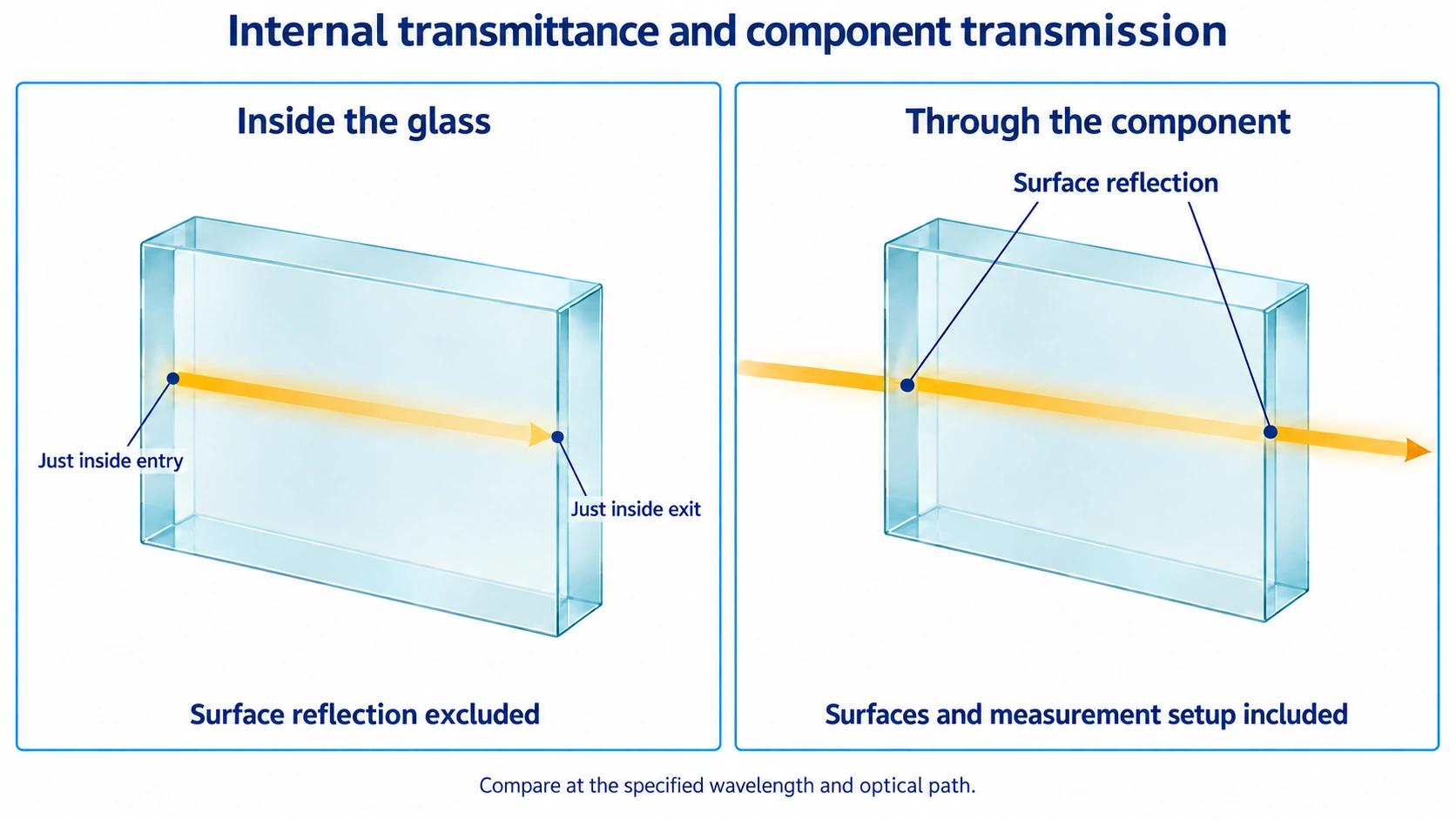
Internal transmittance excludes surface reflection losses. Finished-component transmission also depends on surfaces, coatings and the measurement arrangement. Specify the wavelength range, glass thickness or optical path, surface condition and, where relevant, incidence angle and collection geometry.
Also distinguish typical catalogue values, agreed guaranteed limits and results for a supplied lot. SCHOTT notes that its ordinary catalogue transmittance data generally represent values from multiple melts; minimum values can be agreed separately. A typical value should therefore not automatically become an order acceptance limit. SCHOTT: Transmittance of Optical Glass
For a lens or another refractive component, include the required refractive properties and reference conditions. Transmission alone does not define its optical behaviour.
Define colour, scattering and the evaluated area
Distinguish the appearance of the glass under inspection lighting from the colour of transmitted light. For coloured lighting components, identify the intended source spectrum and measurement method. For opal or translucent parts, include scattering or light-distribution requirements where these determine function.
Define the evaluated area and sampling locations when spatial variation matters. Bubbles, inclusions, striae and colour variation should be assessed against the relevant optical or appearance zones. Reference samples can illustrate acceptable appearance, alongside written criteria for critical features.
The same approach applies when turning material properties into purchase requirements:
| Requirement | Conditions to specify | Acceptance basis to agree |
|---|---|---|
| Spectral transmission | Wavelengths, path length, surface state and measurement arrangement | Minimum transmission or a permitted spectral envelope |
| Thermal expansion | Temperature interval and measurement method | A maximum value or permitted range over that interval |
| Transmitted colour | Source spectrum, measurement geometry and colour evaluation method | Permitted colour coordinates or an agreed comparison criterion |
| Internal quality | Defect types, product zones and inspection method | Applicable size, number and distribution limits by zone |
Set the actual limits from the component's functional requirements and the agreed supply capability.
Establishing a Viscosity–Temperature Working Range
Glass viscosity rises as it cools through the forming range. The relationship depends on composition, so equal temperatures do not imply equal flow behaviour for different grades. Glass transition temperature, softening point and annealing point describe different reference conditions; none supplies a complete pressing recipe. SCHOTT: Mechanical and Thermal Properties of Optical Glass
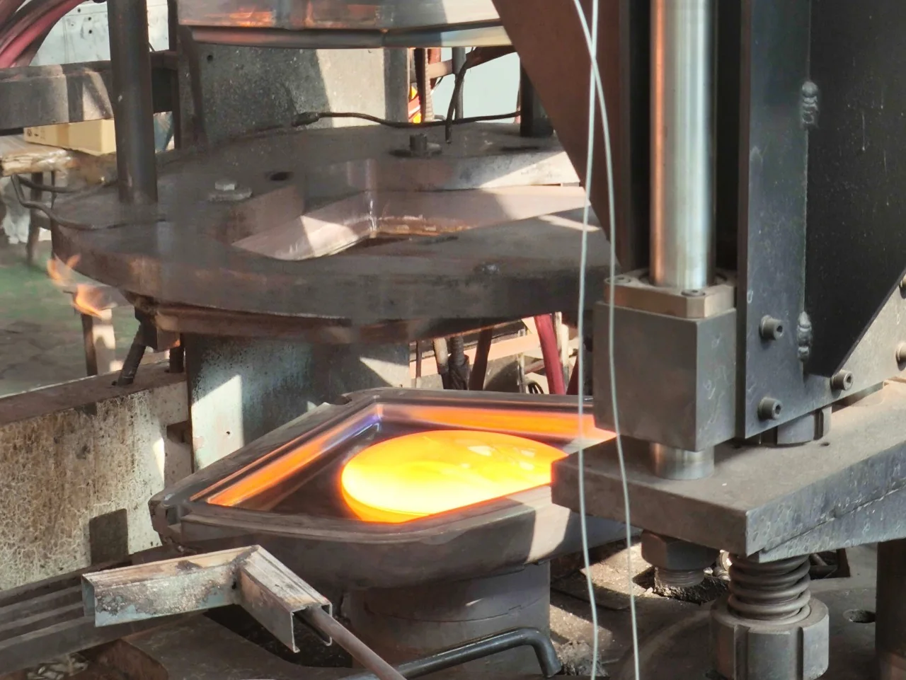
Use material data and trials to establish a working range for the intended geometry, tooling and cycle. The review should connect:
- Flow through the feeder and separation at the shears.
- Gob stability during transfer and filling at the press.
- Plunger resistance, tool interaction and release timing.
- Relevant risks from thermal exposure, including unwanted crystallisation.
For example, equal-mass gobs may fill differently after different transfer delays. Increasing temperature to improve one feature can also alter gob shape, surface behaviour or cycle time.
Keep viscosity units and the supported temperature interval with the data. Evaluate combinations of temperature, timing and tooling conditions; do not assume that every combination of individually acceptable values has been validated.
Controlling Melting Quality, Fining and Composition Uniformity
Material-quality problems can pass from the melt into the pressed part. The preparation stages have distinct purposes:
- Melting: forming the intended glass melt from the supplied materials; batch melting includes reactions and dissolution, while remelting starts with previously formed glass.
- Fining: reducing gaseous inclusions through the selected glassmaking process.
- Composition homogenisation: reducing chemical variations within the melt.
These distinctions follow the glassmaking stages described in RSC: Glass Melting. Composition uniformity and temperature uniformity are separate requirements, although process conditions can influence both.
Control internal defects and contamination
Specify relevant bubble, inclusion and non-uniformity criteria, including the evaluated zones and inspection method. Pressing reshapes glass; it should not be relied on to correct an upstream material defect.
Keep cullet and remelt material identified by composition, source and permitted condition. Review contamination from mixed glass, ceramics, metals, coatings or other foreign material. A rejected article is suitable for remelting only when its composition, cleanliness and rejection reason are compatible with the material-control procedure.
Include furnace, vessel and feeder contact materials in defect investigations. Wear or interaction with the glass may introduce contamination. Compare changes in defect frequency with incoming material, operating history and equipment condition to distinguish pre-existing defects from those introduced later.
Conditioning the Melt Before Gob Formation
Conditioning establishes the thermal state required for feeding and forming. Continuous lines commonly use a distributor and forehearth; other routes may use a working furnace or pot arrangement. HORN's conditioning guidance emphasises temperature homogeneity at the gob and the relationship between the distributor and forehearth. HORN: Glass Conditioning
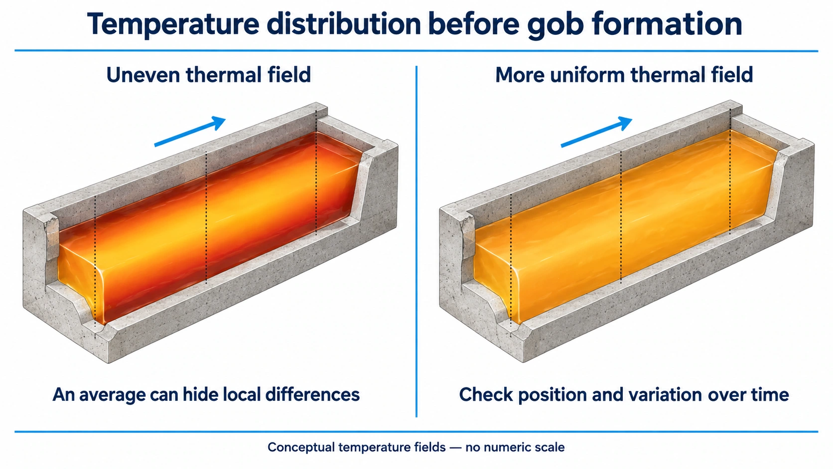
Control distribution and changes over time
Assess temperature variation across the glass stream, through its depth, between outlets and over the production interval. An acceptable average can conceal differences affecting individual gobs.
Throughput changes, interruptions and material transitions can alter thermal balance and residence time. Record the adjustment time, identify the affected production interval and establish when stable output has returned. The response at the gob may lag behind an upstream change; account for that delay before interpreting the result of another adjustment.
Identify what each reading represents
Separate controller setpoints from actual measurements. Identify whether a reading comes from glass, refractory, furnace atmosphere or another location, and record the method and measurement position.
A stable controller reading does not establish uniform temperature throughout the glass. Compare process measurements with gob behaviour and relevant component checks to confirm that the conditioning system supports consistent production.
Coordinating the Feeder and Shears
The feeder and shears must deliver the required glass quantity in sequence with the press. Depending on the equipment, the system may include a bowl, outlet orifice, tube and feeder plunger.
The feeder plunger regulates delivery; the press plunger shapes glass in the mould. Keep their settings and timing references distinct.
Match equipment and timing to the article
Review glass composition, target gob mass, delivery frequency, glass level and downstream arrangement. Identify individual outlets and paths on multiple-gob equipment. Feeder designs can use independently controlled mechanisms, so a common system setting should not replace assessment of each output. WALTEC: Feeder Configurations
Coordinate feeder motion, glass separation, transfer and press readiness. Record the reference event for timing measurements. Changes in cutting time can affect both the separated quantity and how the gob leaves the shears.
Check condition as well as programmed motion
Inspect outlet wear, alignment, blade condition, build-up and the specified cooling or lubrication arrangements. Check the blade relationship through its movement and the consistency of gob ends and departure direction. Shear mechanisms differ by application; adjustments should follow the equipment procedure and established process conditions. WALTEC: Glass Shear Systems
Repeatable motion does not guarantee identical delivered glass when melt condition or contact surfaces change. Verify gob results after relevant adjustments. Manually portioned glass needs corresponding quantity, timing and delivery controls suited to that route.
Setting Gob Mass and Material Allowances
“Gob weight” is the common production term for gob mass. Define the units, measurement stage, sampling method and acceptance limits.
For a part requiring subsequent material removal, a starting estimate is:
Use compatible units and volume and density at the same reference condition. For example, volume in cm³ multiplied by density in g/cm³ gives mass in grams; the removal allowance must also be in grams. An allowance specified as thickness or volume must first be converted to mass.
Include planned trimming, grinding or polishing removal as applicable. Confirm the target through the actual forming and finishing route.
Separate part allowance from production losses
Start-up losses, rejected gobs and rejected articles affect material consumed per accepted component. They are production-yield considerations, not extra mass to add indiscriminately to each gob.
Too little glass may leave features unfilled. Too much may affect closure or create unwanted material at tooling interfaces. Incomplete filling can also result from temperature, timing, positioning or tooling, so increasing mass is not a universal correction.
Measure at a defined stage
Distinguish a collected and cooled gob, an untrimmed formed part and a finished component. If one measurement is used as a proxy for another, validate the relationship and account for removed material. Check wall distribution and feature geometry alongside mass.
Controlling Gob Shape, Transfer and Mould Entry
A gob changes shape and thermal condition between separation and pressing. Free fall, guides, scoops, troughs or funnels can introduce different travel times and contact conditions. Evaluate the full route through to mould entry.
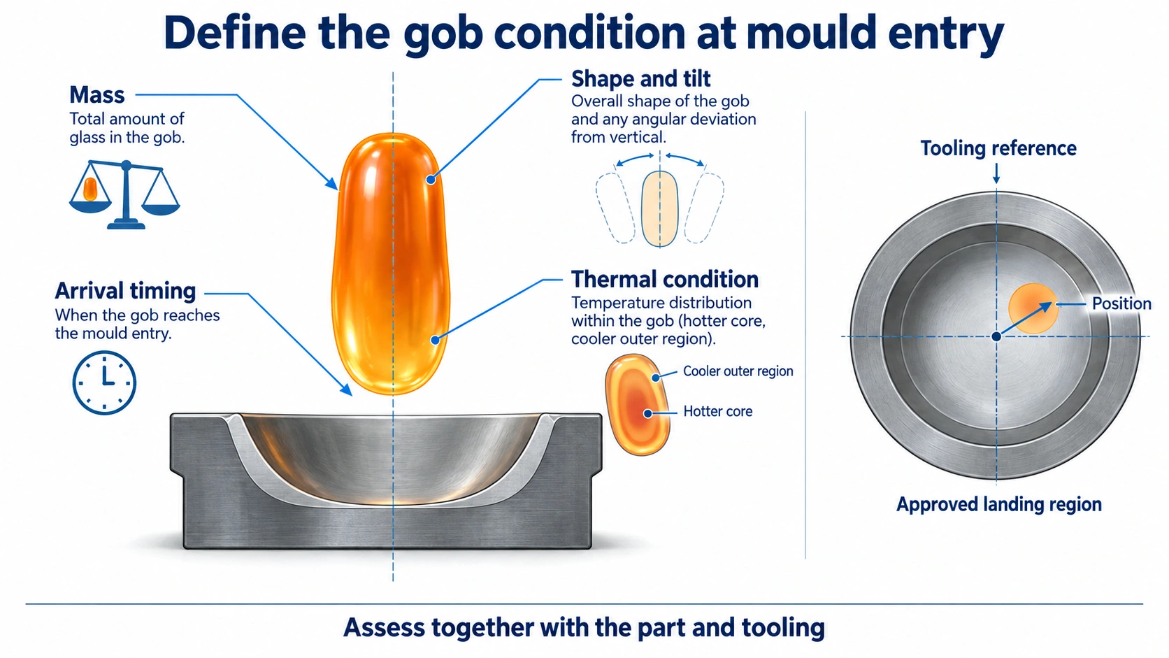
Observe shape and loading at defined locations
Relevant observations may include length, diameter, end shape, curvature and tilt. State where and when the measurement is made: a shape seen below the shears may differ from the shape reaching the mould.
Check transfer time, hesitation, edge contact, alignment, airflow and contact-surface condition. Intermittent contact can cool or distort one region even when mass remains stable. After cleaning, replacement or alignment work, recheck the arrival condition.
Define the intended landing region using the tooling reference system, together with permitted displacement, tilt and entrance contact. Record the relationship between arrival, any settling interval and plunger approach. The approved loading position may be centred or deliberately offset, depending on the design.
Qualify temperature observations
The gob surface and interior may have different temperatures. Infrared readings also depend on the instrument's spectral range, glass transmission and reflection, viewing geometry and background. LAND's gob-measurement guidance specifically discusses alignment and the risk of seeing through the glass. LAND: Temperature Measurement in Glass Production
Record the instrument, spectral range, measurement area, position, timing and relevant settings. Establish whether the result represents a surface region or another effective measurement depth. Identify any inferred internal temperature as an estimate, supported by the chosen method.
Evaluate mass, shape, thermal condition, travel time and entry position together. These describe the glass presented to the press more usefully than a single average temperature or mass result.
Monitoring Variation and Investigating Defects
A monitoring plan should connect feed observations with identified parts, outlets, paths, cavities and production periods. Use continuous monitoring or periodic sampling according to the equipment, process risks and agreed inspection plan. Define who records results, when checks occur and what triggers intervention.
The following table organises investigations; its entries are possible checks, not confirmed causes.
| Observed issue | Information to compare | Production reference to retain |
|---|---|---|
| Incomplete filling despite stable mass | Glass thermal condition, transfer delay, entry position, press timing and mould condition | Gob observation, affected cavity and matching cycle or interval |
| Uneven wall distribution | Mass, gob shape, landing position and tooling alignment | Component orientation, delivery path and measurement locations |
| Mass drift or intermittent variation | Measurement stage, glass level, feeder condition, melt readings and shear timing | Outlet, sample sequence and adjustment times |
| Surface lines, folds or local marks | Gob ends after cutting, transfer contact, arrival orientation and mould-contact locations | Images from the relevant stages and defect location on the part |
| Increased bubbles, inclusions or striae | Material and cullet identity, melt records and glass-contact component condition | Melt or working vessel, production interval and inspection zone |
| Changed colour or transmission | Grade and lot, optical path, surface/coating condition, test setup and thermal history | Material records, component lot and comparable test conditions |
Separate process states and evaluate corrections
Review start-up, stable production, interruptions and transitions separately. Compare individual paths before relying on a combined average. When an issue affects one path, investigate local transfer and tooling evidence alongside shared supply conditions.
Distinguish production targets, operating limits, alarms and product acceptance criteria. Record corrections and evaluate the subsequent gob and component results over an appropriate observation period. A better-looking cut, for example, is not sufficient if mass or entry consistency deteriorates.
Contain affected production and confirm recovery
Define the response to missing, delayed, duplicated or visibly unsuitable gobs. Divert or exclude them through the established procedure and identify potentially affected parts. Resume normal production after confirming the required delivery and pressing sequence and relevant quality checks.
Keep material intended for remelting separate from other rejects, subject to the composition and cleanliness controls described above.
Agreeing Supply Requirements, Traceability and Changes
The supply specification should connect material identity, manufacturing responsibilities and finished-component acceptance. It should also identify which requirements are fixed and which alternatives may be evaluated.
| Specification item | What to agree |
|---|---|
| Material and supply | Manufacturer, grade, permitted alternatives, supply form and material identification |
| Performance | Required optical, thermal, chemical and appearance properties, with test conditions and acceptance limits |
| Internal quality | Relevant defect categories, inspection zones, sampling and evaluation method |
| Handling and remelt | Cleanliness, packaging, storage and permitted cullet or remelt sources |
| Process responsibility | The party controlling melting, conditioning, feeding and associated records |
| Verification | Required certificates, lot-specific results and finished-component checks |
| Changes and traceability | Notification or approval requirements, affected characteristics and links between material and part lots |
Keep material and production records connected
Retain supplied lot and batch or remelt identification, working-vessel identity, production dates and intervals, outlet or path, process revision and inspection results. For continuous production, account for the transition between a material input change and the affected output; the two events need not coincide.
A change within the same glass family can still affect properties and processing. Assess the characteristics affected by a grade, source or process change and determine the necessary trials and verification. Record the approved revision before releasing production under the changed conditions.
Request a glass selection and quotation review
Send BO-Glass your component drawing, intended application and service conditions, specified grade or required properties, and expected quantities. These details support a review of material suitability, supply options and the scope needed for quotation.
For an existing production issue, also include the defect description, affected lots and available material, process or inspection records.
Contact Us
Your feedback fuels our growth, and your questions drive our solutions.
We value your feedback, inquiries, and suggestions. Please feel free to get in touch with us
General inquiries
Please contact us via sales@bo-glass.com, and we will reply to you as soon as possible.
Interested to work with us
Drop your resume at info@bo-glass.com
and we will get back to you shortly.
We uses the contact information you provide to us to contact you about our relevent content, products, and services.