
Glass Screen Printing Fundamentals and Design Guidelines
Translate visual intent into artwork that can be printed, inspected and repeated on the specified glass.
Engineering note: Typical starting values are provided for reference. Final tolerances and process parameters should be confirmed through sample trials using the specified glass, ink system, artwork and firing conditions.
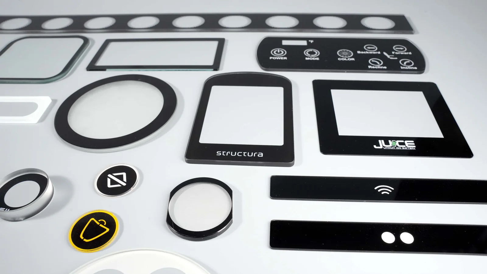
Screen printing is a controlled transfer process
A squeegee drives ink through open areas of a stencilled mesh while the screen separates from the glass behind the print stroke. The deposited film is shaped by the artwork, mesh opening, thread diameter, stencil profile, ink rheology, squeegee condition, off-contact, print speed and substrate support. A sharp vector file is therefore necessary, but it cannot guarantee a sharp print by itself.
Glass surface energy, cleaning residues, coatings, curvature, edge geometry, hole position, float-glass side, thermal history and optical background can all change appearance or adhesion. The drawing should identify the actual glass construction and the printed surface. “Clear glass” is not a complete material specification.
The most reliable quotation begins with the performance requirement and works backward. Define whether the print is decorative, functional, light-masking, heat-exposed, weather-exposed or part of a regulated product. Then identify the cure route and inspection method before finalizing line width, coverage and registration.
- Supply vector artwork at final scale with fonts outlined and overlapping paths resolved.
- Identify viewing side, print side, glass type, thickness range, coatings, holes, cut-outs and edge finish.
- Define color under a named illuminant, observer, geometry, backing and measurement location.
- State the use environment, cleaning agents, temperature exposure, abrasion and target life.
- Agree which characteristics are critical to function and which are cosmetic.
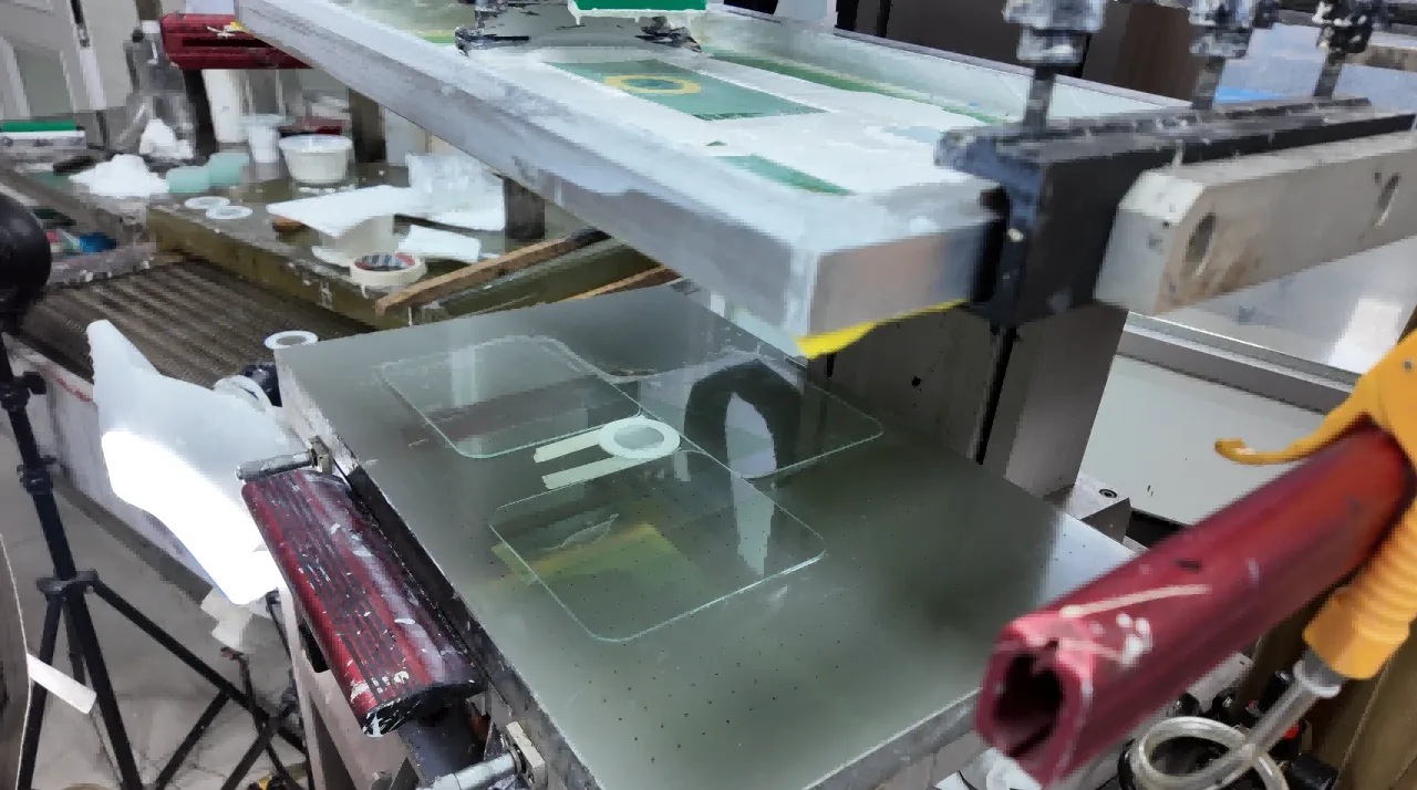
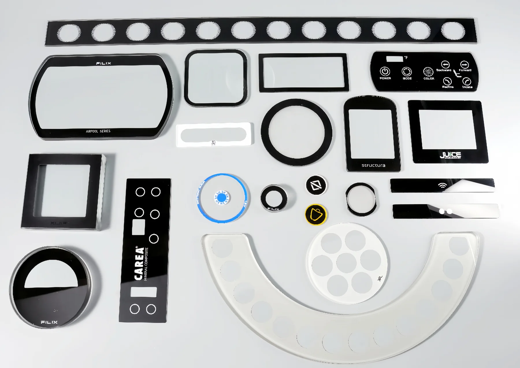
Use starting values as a feasibility conversation
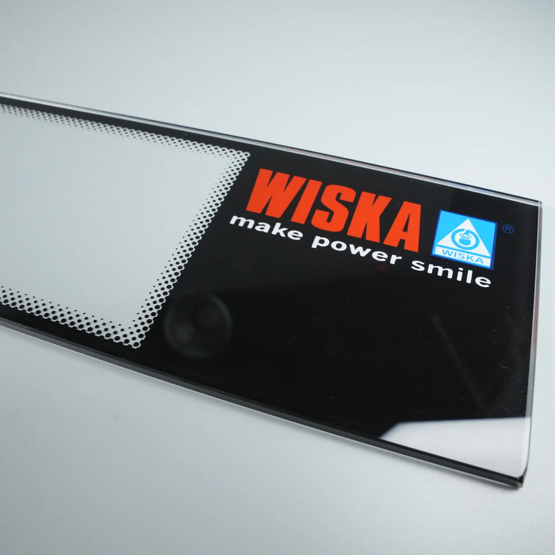
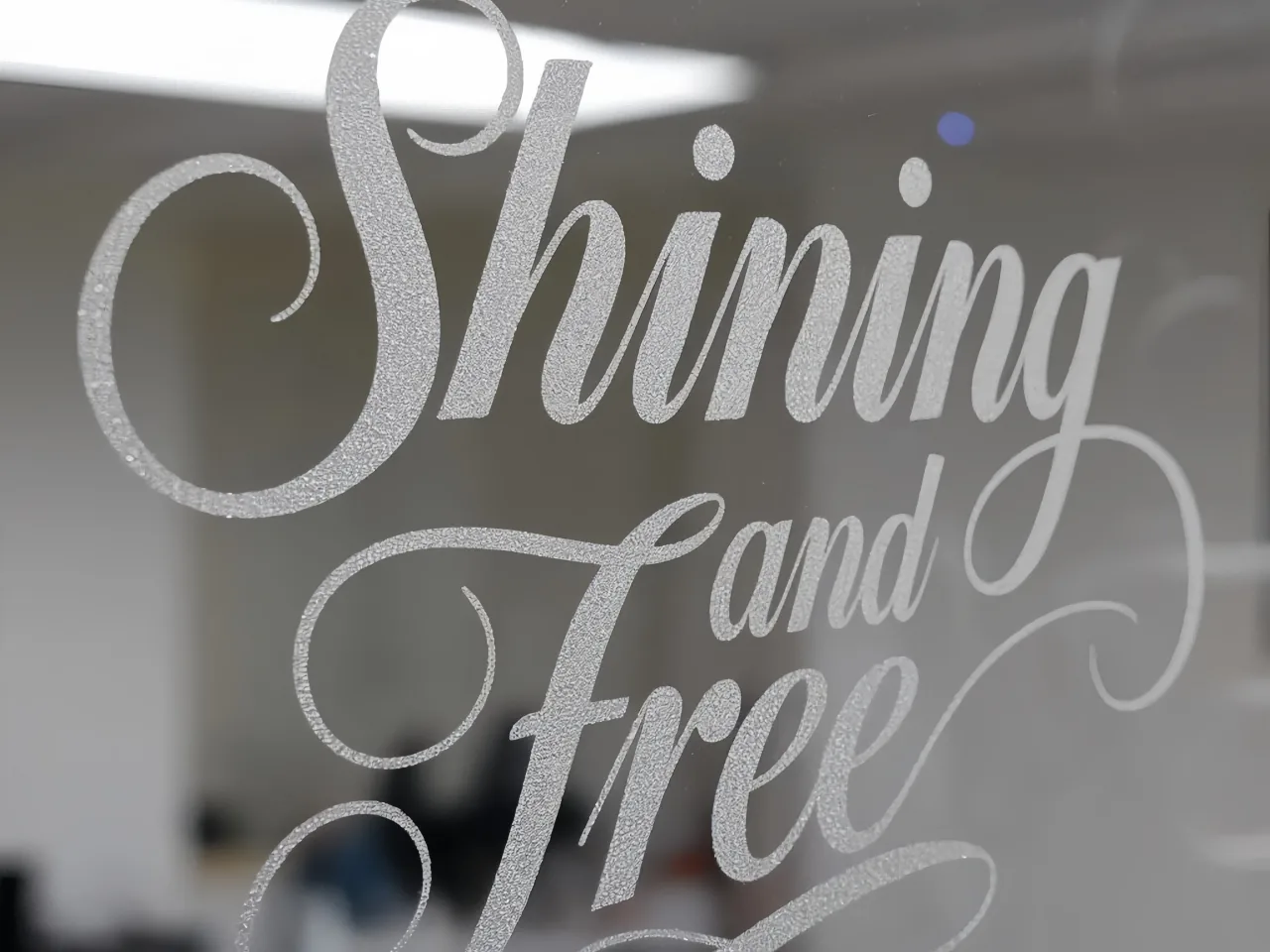
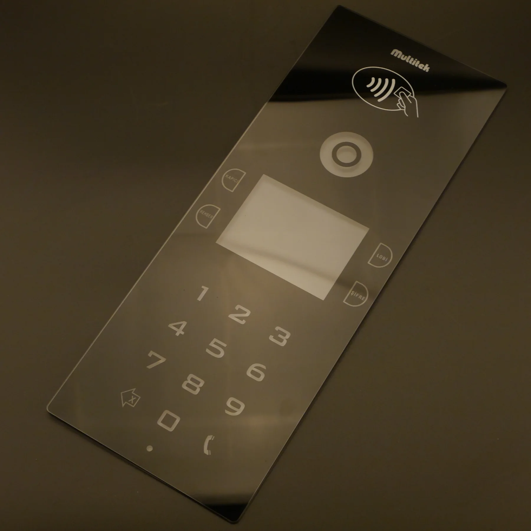
A minimum line width such as 0.15 mm or 0.30 mm is not an industry-wide pass/fail limit. A small isolated positive line, a reversed line within a solid field and a halftone dot do not behave the same way. Mesh count, thread diameter, stencil thickness, ink particle size, print orientation and inspection distance all matter. Fine artwork should be classified by feature type and tested at production scale.
For an early design review, the printer may propose a conservative feature range based on a known screen and ink combination. That value should be labelled “typical starting point,” accompanied by the assumptions used to produce it, and replaced by an approved sample or capability result before release. The same discipline applies to small type, corner radii, gaps, knockouts and line-to-solid transitions.
Large solids and fine detail can sometimes share a screen, but the process window becomes narrower. The mesh and stencil suitable for high ink deposit may not resolve fine reverses cleanly. Separate screens or adjusted artwork may be more robust when both features are critical. A stepped artwork test is more informative than debating a single universal number.
| Feature | Early review question | Confirm by |
|---|---|---|
| Fine positive/reversed lines | Can the selected mesh, stencil and ink resolve both orientations? | Stepped line target on production glass |
| Small text | Are stroke width, counters and viewing distance defined? | Print sample at final size and inspection distance |
| Large solid area | Is deposit uniformity more important than edge resolution? | Coverage, thickness and optical-density mapping |
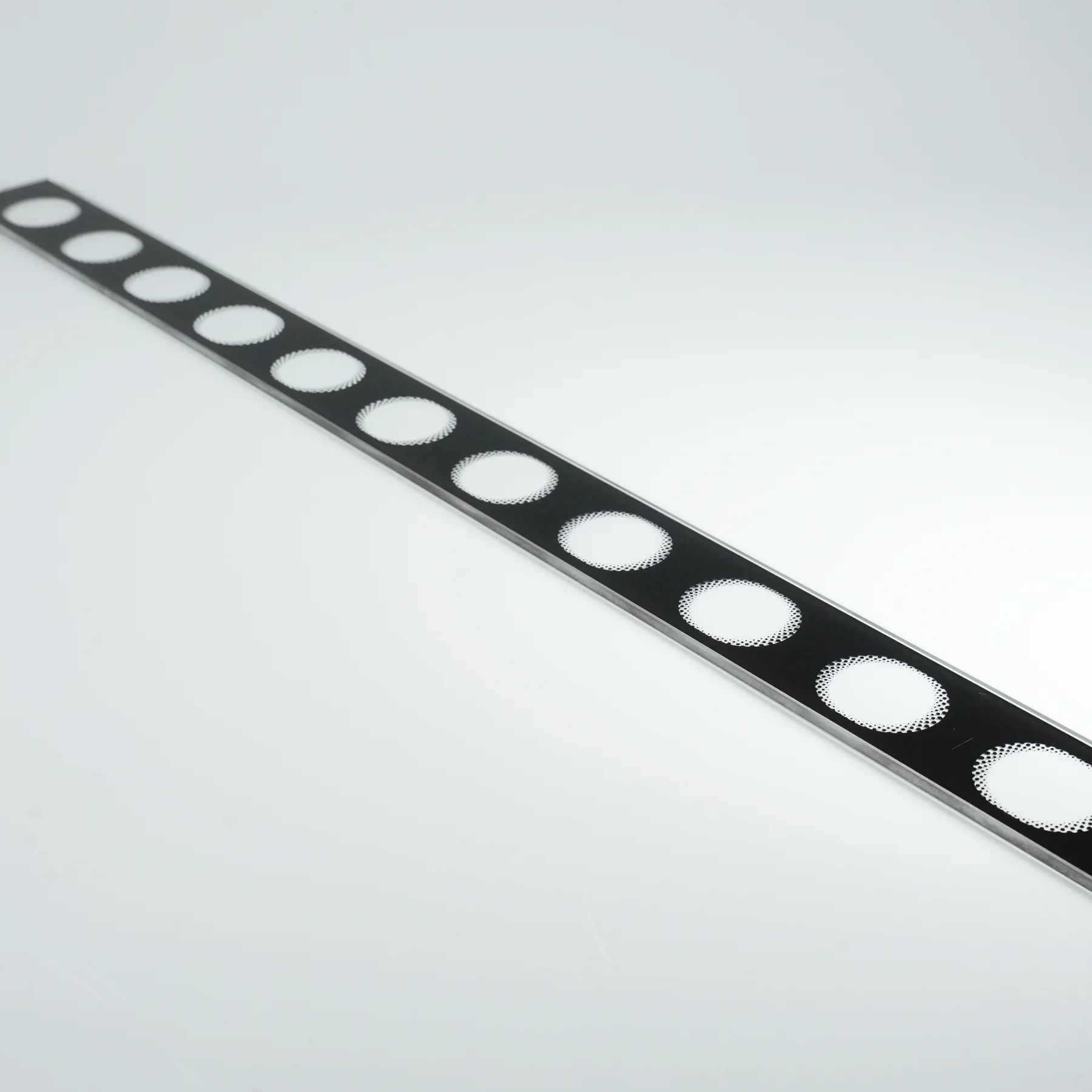
| Halftone or gradient | Are dot shape, angle, tonal range and moiré risk specified? | Screened tonal wedge and visual approval |
| Multi-color trap | Does the trap tolerate total stack-up of print, fixture and glass variation? | Worst-case registration study |
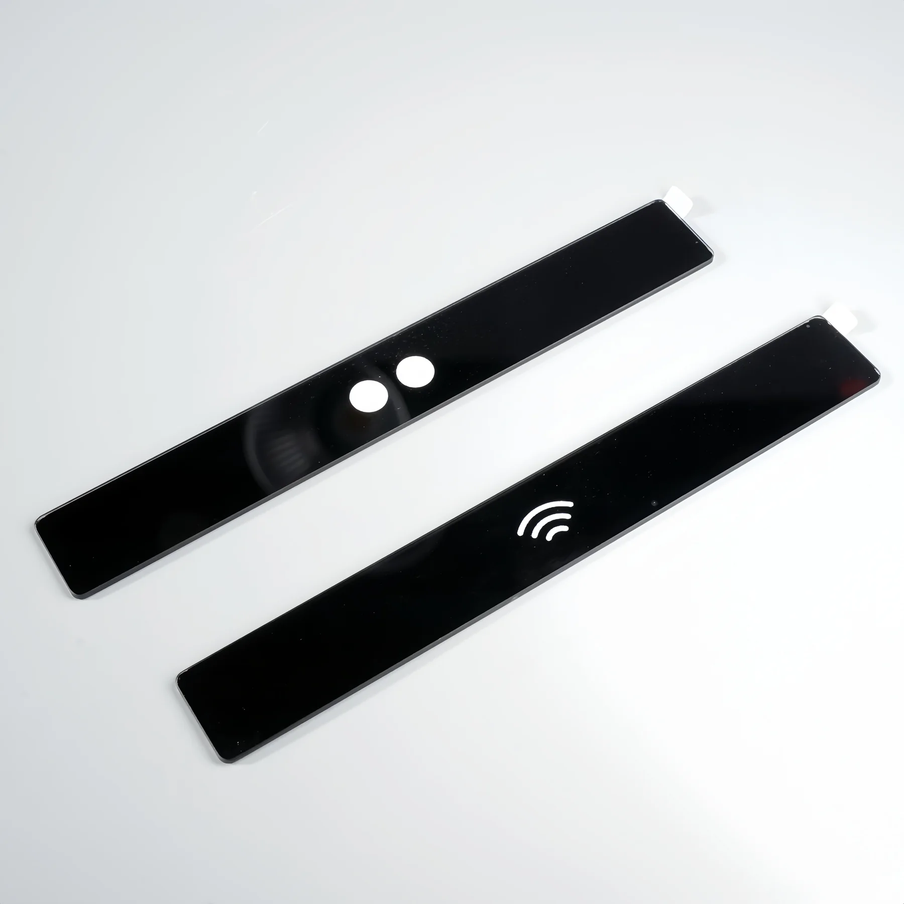
Design registration around the full tolerance stack
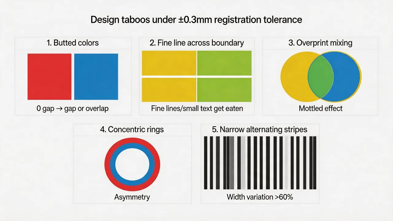
A statement such as “registration is ±0.3 mm” is incomplete unless it identifies the datum, measurement method, panel size, number of colors, equipment and process stage. Glass dimensional variation, fixture repeatability, screen stability, camera alignment, thermal movement and operator setup can accumulate. The design should tolerate the expected combined variation rather than rely on one nominal press value.
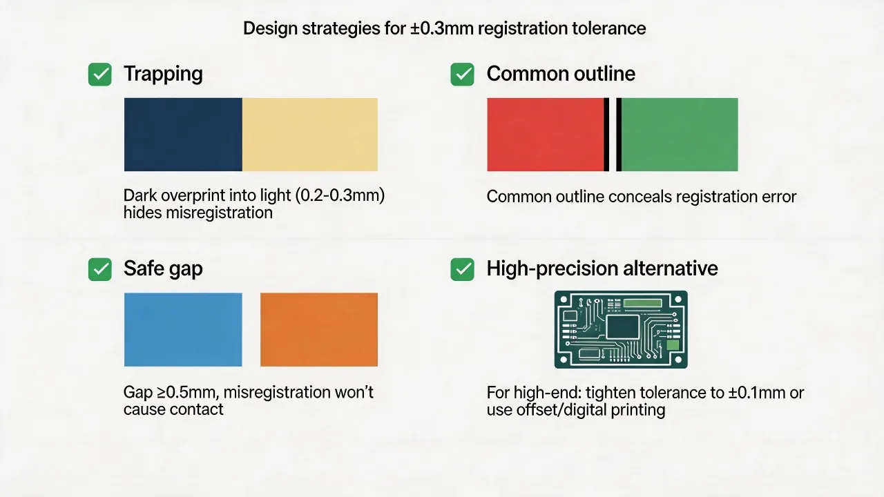
Trapping is a deliberate overlap between adjacent colors. It prevents a light gap from appearing when one color shifts relative to another. The amount and direction of trap depend on color order, opacity, viewing side and acceptable edge appearance. Choking a light color under a dark border is common, but not automatically correct for translucent or backlit work.
Avoid using two high-contrast colors that meet on a hairline boundary when the boundary is visually critical. A keyline, controlled overlap, common-color border or single-screen redesign can be more stable. Registration targets placed outside the finished viewing area help during setup; production inspection should still measure the functional features on the part.
- Name the drawing datum and indicate whether tolerances are to glass edge, hole, printed fiducial or fixture datum.
- Separate color-to-color registration from print-to-glass positional tolerance.
- Include glass-size and hole-position tolerances in the stack-up.
- Validate after any thermal step when the final appearance depends on fired or tempered geometry.
Treat holes, edges and curvature as process zones
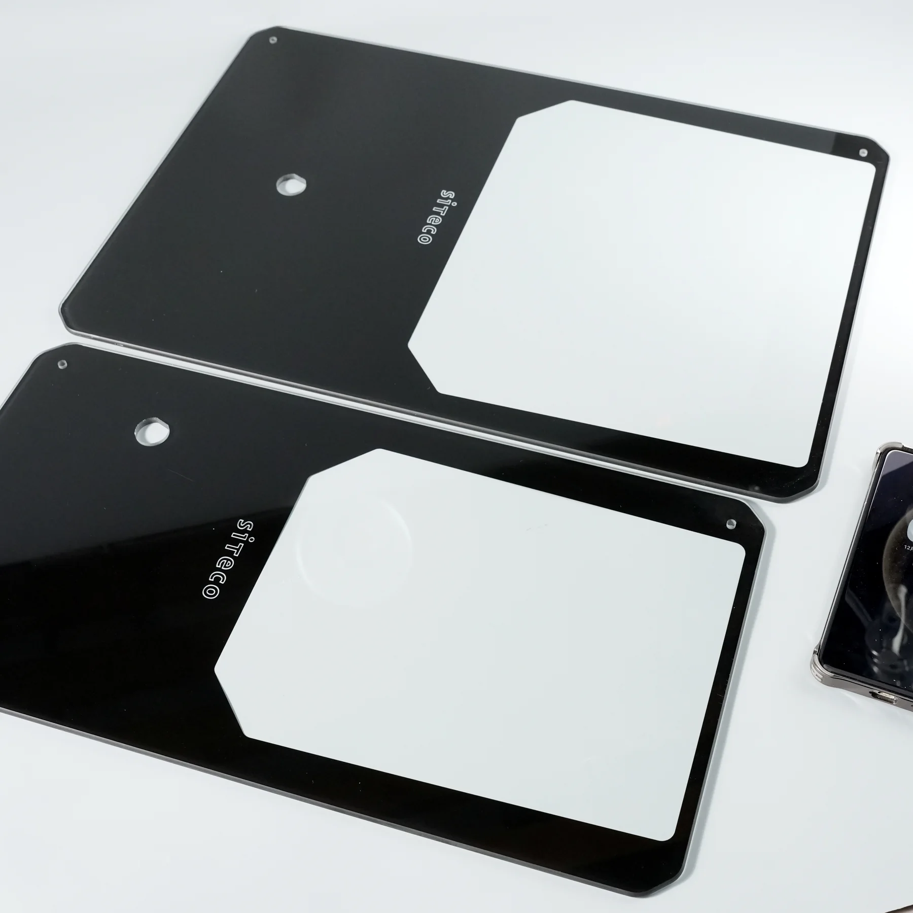
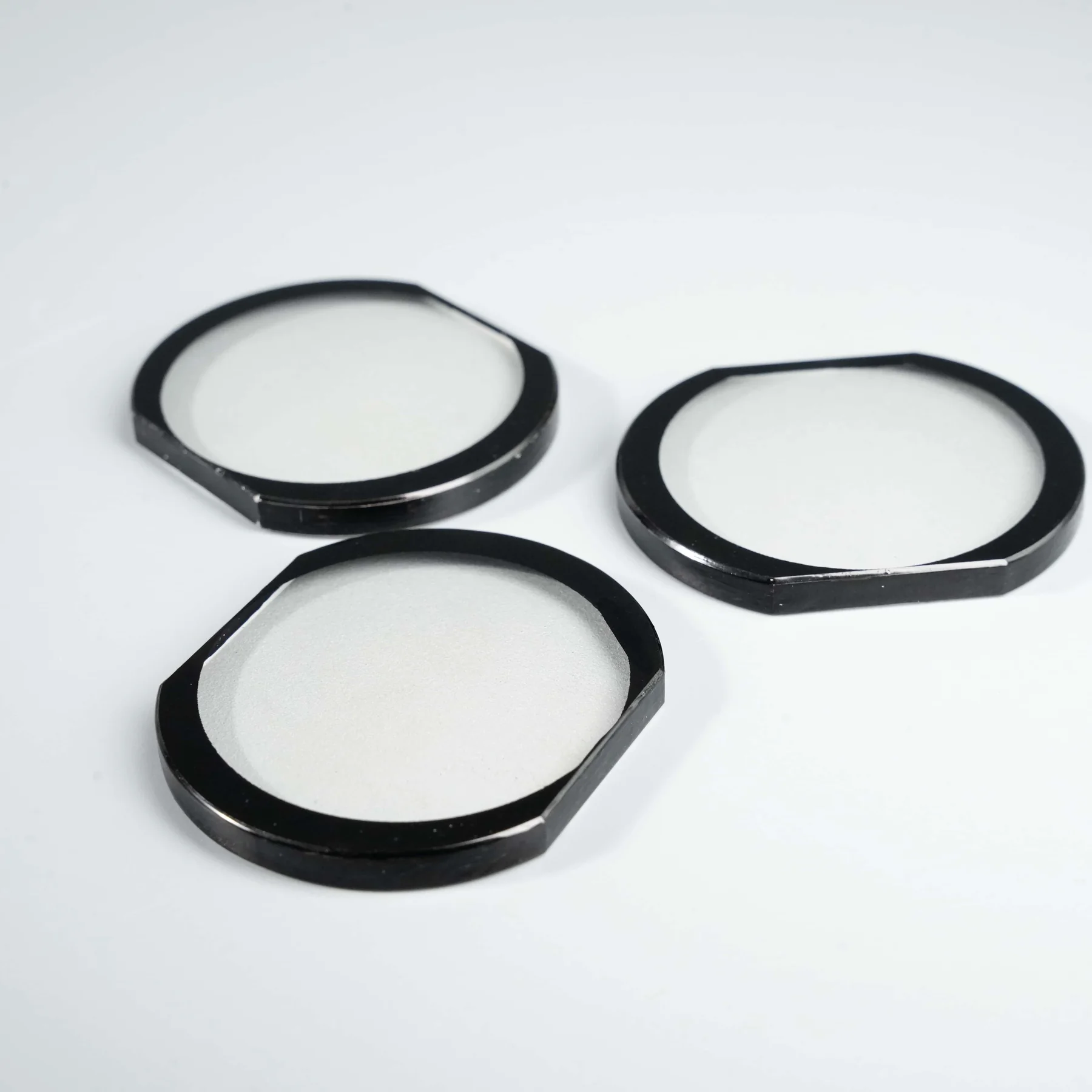
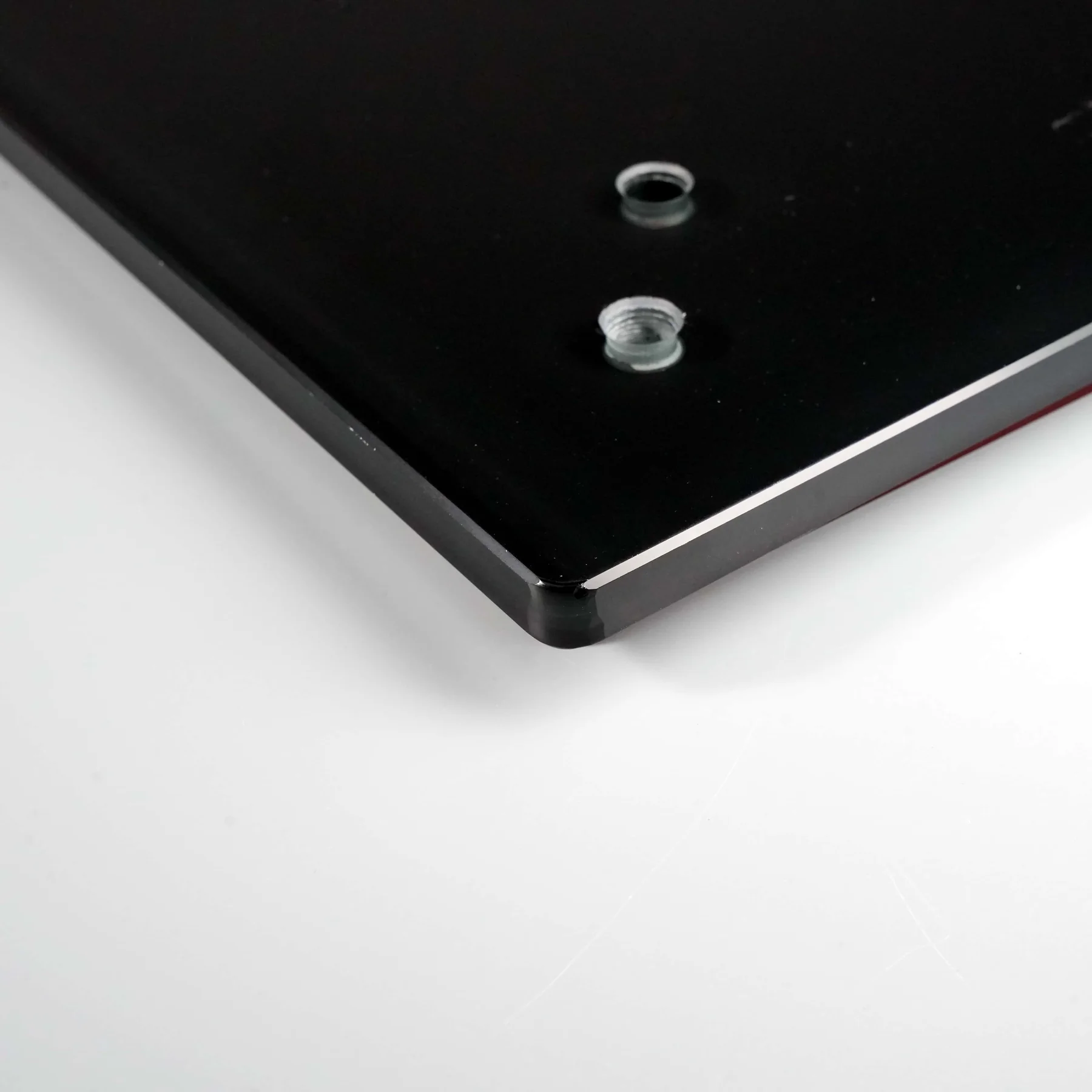
Printing close to a hole or shaped edge is not impossible simply because a generic safe distance has been crossed. Risk increases because the glass may be less supported, the squeegee may deflect, ink may pool at a relief, and positional variation becomes more visible. Chamfers, arrisses and edge chips can also change the apparent boundary. The workable distance should be established from the actual geometry, support tooling and inspection requirement.
Curved or formed glass requires a screen and squeegee path that maintain controlled contact and peel. The fact that a squeegee can physically touch the surface does not prove that the deposit or position will be accurate. Compound curvature, local slope, fixture repeatability and screen deformation can make conventional flat-bed printing unsuitable. Purpose-built tooling, shaped screens, pad printing or another decoration method may be preferable.
For tempered products, distinguish two routes. Ceramic enamel is normally printed before tempering and fused during the thermal cycle when high heat and durability are required. Printing after tempering generally uses a lower-temperature organic system because the glass cannot simply be reprocessed as though it were annealed. Each route has different adhesion, heat resistance, color and validation limits.
Measure color and transmission under defined conditions
The glass is part of the color system. Low-iron and conventional clear glass can make the same white print appear different, but a universal ΔE range cannot be predicted without specifying glass thickness, tint, ink batch, film thickness, firing history, illuminant, observer, measurement geometry, backing and instrument settings. Approve color on the specified construction, not on a detached ink chip.
Statements that one ink family transmits more light than another are similarly incomplete. Transmission depends on pigment, loading, film thickness, wavelength and measurement method. A backlit graphic may need spectral transmission, luminance uniformity and pinhole criteria rather than one photopic percentage. A decorative opaque border may instead be controlled by optical density or contrast ratio.
Specify whether color is evaluated from the printed side or through the glass. For second-surface printing the substrate modifies both color and gloss. The approval sample should record the viewing direction, background and light source so that production and customer inspection reproduce the same condition.
| Item | Record |
|---|---|
| Construction | Glass type, thickness, coatings, print side and viewing side |
| Ink film | Ink code, batch where relevant, screen/stencil and print passes |
| Thermal history | Cure or firing profile and tempering status |
| Measurement | Instrument, geometry, illuminant, observer, aperture and backing |
| Acceptance | Master sample plus agreed numerical and visual criteria |
Release a print specification, not only artwork
A production-ready package combines drawing, material definition, approved appearance and validation plan. It should say how defects are viewed and measured. Inspection at close range under intense raking light will find features that are invisible in service; a vague “no defects” clause invites disagreement. Define viewing distance, illumination, background, inspection time and critical zones.
Use a golden sample or signed first article to capture interactions that a drawing cannot fully describe. Preserve the screen, ink, cure and instrument records that created it. If a later change affects the glass, ink, screen, artwork, fixture or thermal profile, assess whether requalification is required rather than assuming the old approval still applies.
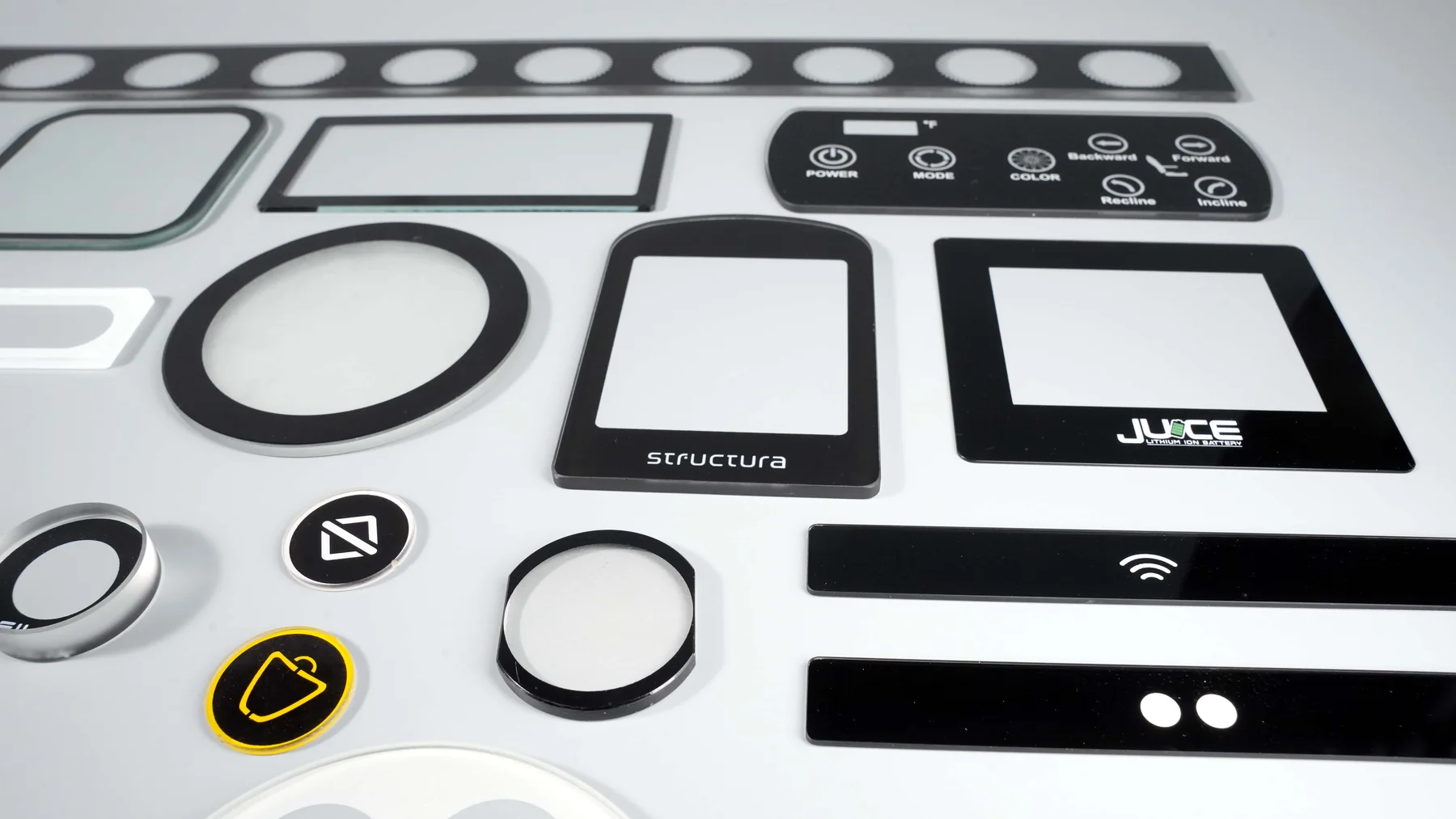
Applications such as oven panels, medical components, architectural glazing and packaging each impose different risks. The design method is common, but the acceptance plan is not. Heat exposure, human contact, outdoor weathering, dishwasher cleaning, sterilization or food-contact requirements must be translated into product-specific tests by the responsible manufacturer and customer.
Contact Us
Your feedback fuels our growth, and your questions drive our solutions.
We value your feedback, inquiries, and suggestions. Please feel free to get in touch with us
General inquiries
Please contact us via sales@bo-glass.com, and we will reply to you as soon as possible.
Interested to work with us
Drop your resume at info@bo-glass.com
and we will get back to you shortly.
We uses the contact information you provide to us to contact you about our relevent content, products, and services.