
PAPI Lenses, Filters & Optical Components
Engineering considerations for PAPI lenses, red filters, transition accuracy, environmental exposure, and replacement optics.
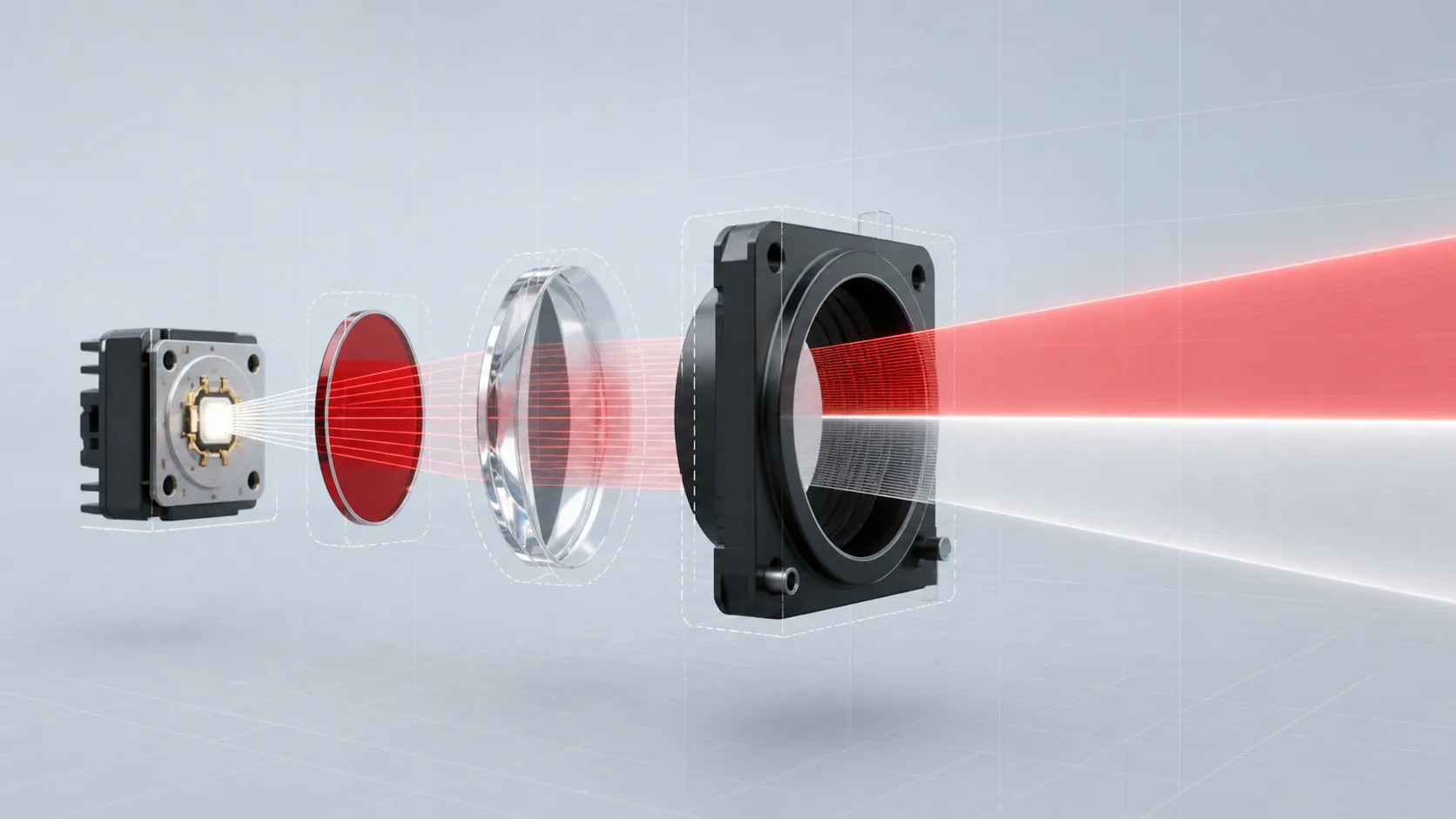
PAPI Lenses, Filters and Optical Components
A PAPI indication depends on a sharply controlled red-to-white transition viewed from a long distance. Small changes in source position, lens alignment, filter spectrum, contamination, or temperature can move or blur that transition even when each component appears acceptable on its own. The following questions explain the optical chain behind the indication and why system-level measurement matters more than judging a red filter or lens in isolation.
What does a PAPI optical system communicate to a pilot?
A Precision Approach Path Indicator provides visual glide-slope guidance by presenting a pattern of red and white light units. The observed combination tells the pilot whether the aircraft is above, on, or below the defined approach path. Each unit produces an upper white sector and lower red sector separated by a narrow transition.
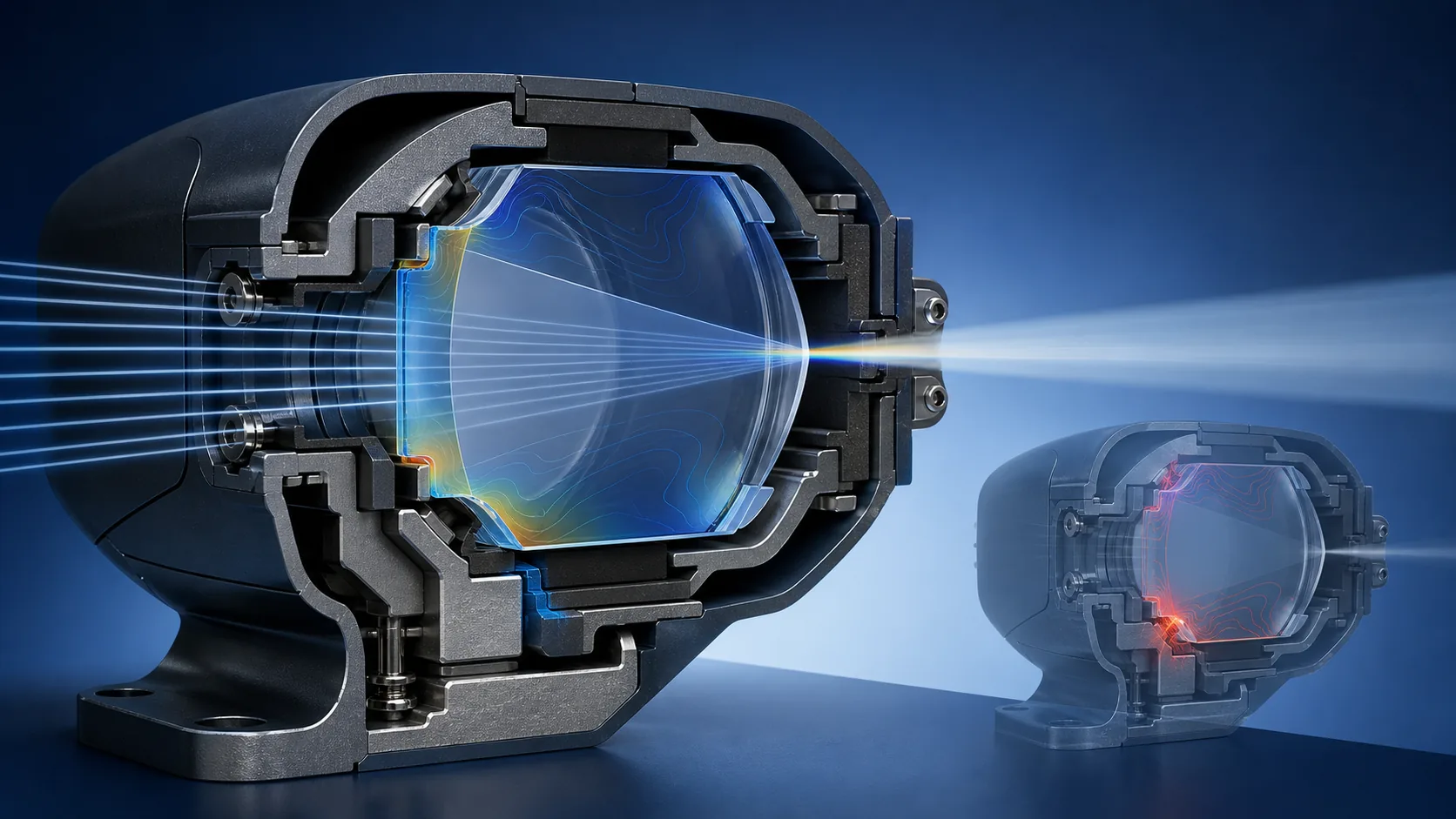
Because the signal is angular, the optical system must be stable in geometry, color, intensity, and alignment. The lens, filter, source, reflector, baffles, housing, mounting, and aiming device all contribute. Contamination, frost, settlement, vibration, or thermal distortion can alter the apparent transition or reduce visibility. FAA AC 150/5345-28H is the current U.S. PAPI equipment specification as of August 12, 2026. It covers Type L-880 four-unit and L-881 two-unit systems, environmental classes, photometry, color, lens requirements, aiming, monitoring, qualification, and production tests. Glass suppliers should treat PAPI optics as system-critical components and preserve the controlled geometry and spectral behavior established by the equipment manufacturer.
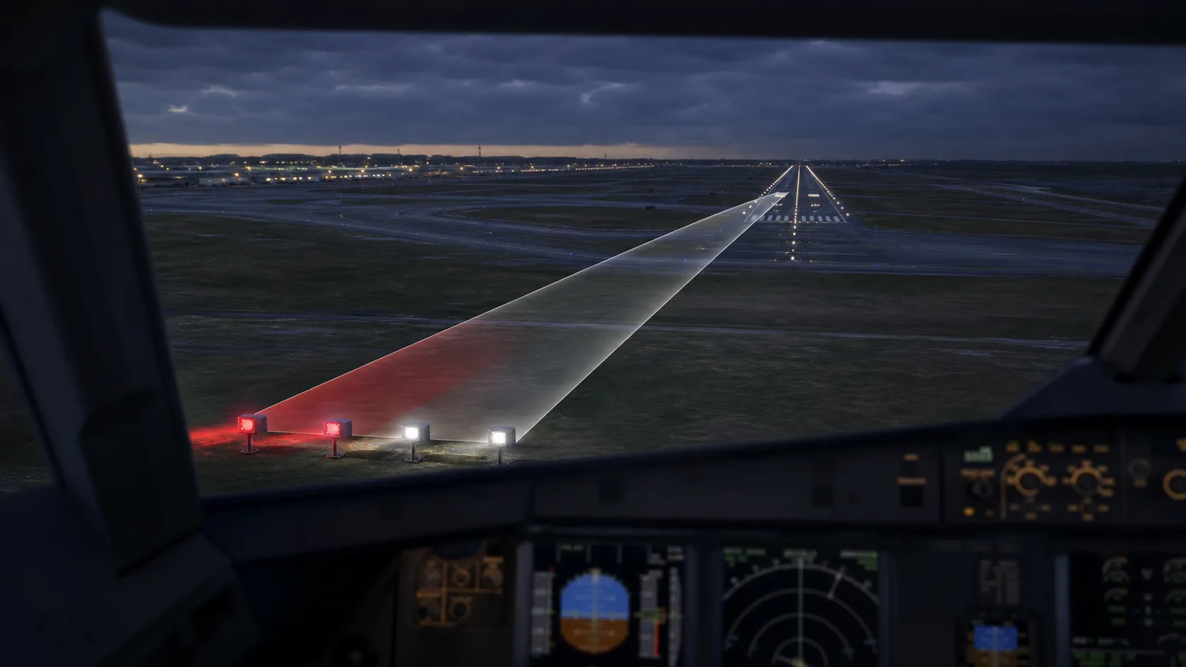
Why is the red-to-white transition so demanding?
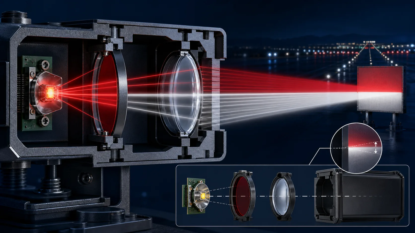
The PAPI transition is demanding because a very small vertical angle carries approach-path information. A transition that widens, curves, or moves can change what the pilot sees even when the unit still appears bright.
FAA reference points at 1,000 ft (300 m):
- red-to-white transition within 3 minutes of arc at beam center;
- transition within 5 minutes of arc at beam edges;
- the transition-center line at +10°, 0°, and −10° straight within 3 minutes of arc;
- transition-band flatness within 3 minutes of arc.
These values come from the complete light-unit requirements in FAA AC 150/5345-28H. Lens profile, wedge, filter edge, source geometry, mounting stress, contamination, and thermal movement can all consume that angular allowance. Component metrology helps control those contributors, but the assembled PAPI unit supplies the final evidence.
PAPI specification and acceptance matrix
Define the complete PAPI configuration first, then separate component evidence from the measurements that must be completed on the assembled light unit.
| Project input | Define on the project | Component evidence | Complete-unit acceptance |
|---|---|---|---|
| PAPI type | L-880 or L-881 and environmental class | Model and controlled drawing | Configuration confirmation |
| Light source | Incandescent or LED, spectrum, position and operating point | Source inspection record | Chromaticity and intensity |
| Red filter | Spectral curve, thickness, edge position and orientation | Spectral and dimensional report | Red sector and red/white transition |
| Lens | Profile, refractive index, wedge and centration | Optical and dimensional measurement | Complete beam measurement |
| Mounting datums | Seat, retainer, orientation and clamping condition | Drawing and assembly inspection | Transition position and straightness |
| Environmental control | Temperature class, heating, drainage and overhang | Component and assembly records | Transition, color and output after environmental exposure |
| Documentation | Drawing revision, lot, certificate of compliance and approved exceptions | Supplier documentation package | Qualified-configuration record |
PAPI red-filter and source matching
A PAPI red filter creates the red sector by transmitting the required red wavelengths while suppressing spectral energy that would move the signal outside the specified aviation-red chromaticity region. Its task is not simply to look red: it must preserve adequate intensity and a sharp, stable red/white transition in the configured optical unit.
The useful transmission curve depends on filter material, thickness, temperature, incidence angle, surface finish and any coating. Heat from the source can create local temperature gradients, while contamination or coating change can reduce transmission or scatter light across the transition.
Evaluate the filter with the actual PAPI source and optical geometry. Measure spectral transmission and chromaticity at the relevant temperature and angles, then verify transition width, color and intensity in the complete PAPI unit. See Glass thickness, color and LED source matching for the general spectral-validation method.
A PAPI red filter is selected as part of the source-filter-lens system, with the red-to-white transition confirmed in the complete unit.
Environmental control: temperature, contamination, heating and drainage
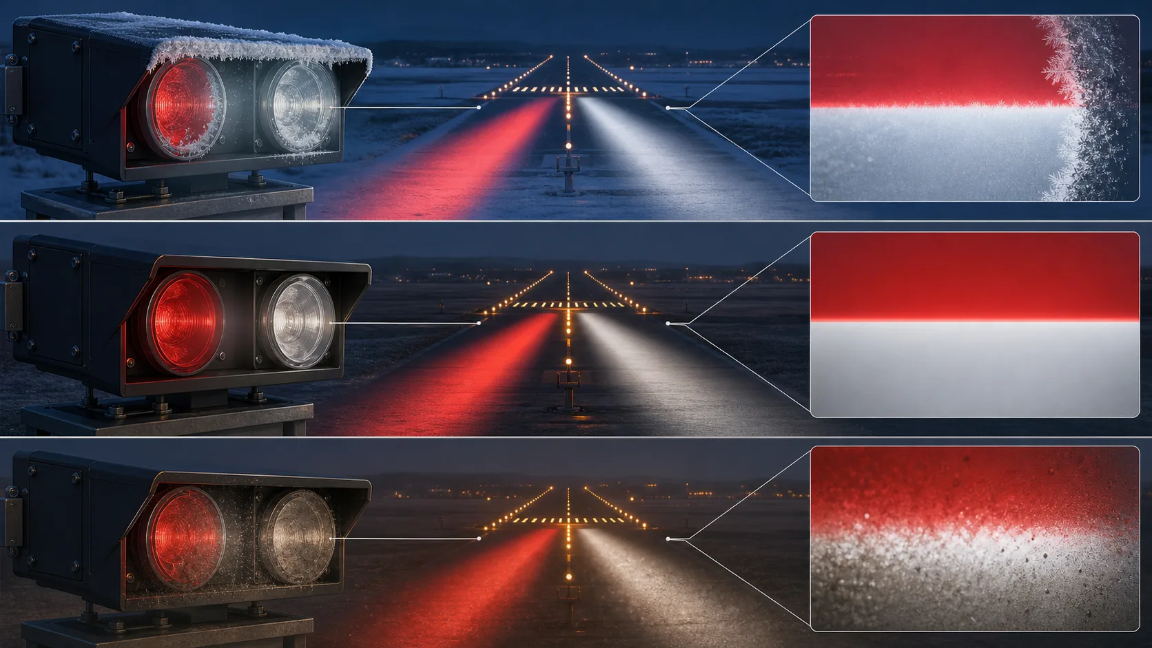
PAPI environmental control protects an angular safety signal, not merely a clear viewing surface. Temperature changes can affect refractive index, source output, filter transmission, seal compression and mechanical alignment. Dew, frost, rain, snow and contamination can scatter light, reduce intensity or blur the red/white transition. Overhangs, heaters, drainage, seals and maintenance procedures must therefore work as one complete-unit design.
| Environmental factor | Possible effect | Design control | Verification |
|---|---|---|---|
| Temperature change | Refractive-index change, structural expansion, source-output shift and transition-angle movement | Material matching, mounting clearance and thermal analysis | Complete-unit optical checks at high and low temperature |
| Condensation and frost | Scatter, optical loss and a blurred or displaced transition | Thermostatic heating and temperature control | Cold-start and humidity testing |
| Rain and snow | Partial obstruction and non-uniform output | Protective overhang, drainage and surface design | Optical inspection after precipitation exposure |
| Contamination | Lower transmission and increased stray light | Approved cleaning method and maintenance interval | Transition and output checks before and after cleaning |
| Non-uniform heating | Glass stress, local deformation and alignment change | Controlled heater position and temperature gradient | Complete optical-path check in the heated state |
FAA AC 150/5345-28H requires protection against rain and snow accumulation and prevention of dew or frost/ice on lens surfaces through the applicable complete-unit design. Glass thickness, thermal conductivity, rim geometry and coatings influence that design, but clear glass alone cannot demonstrate compliance. Qualification should verify the transition, color and output after the applicable environmental exposure; field troubleshooting should include heater operation, thermostat function, blocked drains, damaged seals, contamination and incorrect replacement optics.
What lens compliance documentation is required for a PAPI system?
FAA minimum requirement
FAA AC 150/5345-28H requires a certificate of compliance from the lens manufacturer confirming that the applicable lens requirements have been met. The exact technical basis depends on whether the PAPI uses incandescent or LED light sources. For incandescent configurations, the applicable references include the specified MIL-C-7989 cover requirements and SAE AS25050 color requirements; LED configurations follow the exceptions and chromaticity provisions stated in the AC.
Recommended certificate content
For effective configuration control, the certificate can also identify the manufacturer, part number, drawing revision, production or qualification lot, applicable requirement, supporting evidence, approved exceptions, and authorized signatory. These details are recommended quality-documentation practice; they should not be presented as a verbatim FAA checklist when the AC does not enumerate them individually.
How should PAPI optical parts be packaged and handled?
- PAPI lenses and filters need protection from chips, scratches, coating contact, contamination, and orientation errors. Use non-abrasive individual separation, edge protection, clean bags or wraps compatible with coatings, and rigid outer packaging. Prevent glass-to-glass contact. If desiccant is used, keep it from touching coated surfaces and validate the packaging materials for long storage.
- Label the part number, revision, lot, orientation, coated side, quantity, and handling precautions. Where matched filters or optical sets are qualified together, keep them identified as a set. Packaging should survive international vibration and drop conditions appropriate to the distribution route without transferring point loads to the lens.
- At receipt, inspect packaging damage before opening, then verify identity, coating side, edges, cleanliness, and documents. Store in a dry, temperature-controlled area away from corrosive vapors. Technicians should wear clean gloves and use approved cleaning methods. A pristine optical report is of little value if the part is chipped or contaminated between final inspection and installation.
PAPI optical tolerance chain
The transition is created by the complete source-filter-lens assembly. Allocate angular error before releasing component drawings so individual tolerances do not consume the complete-unit allowance independently.
| Contributor | Control | Verification |
|---|---|---|
| Source | Emitting position, spectrum or LED bin, operating point and temperature | Source inspection plus complete-unit color and photometry |
| Red filter | Spectral curve, thickness, edge position, wedge and orientation | Spectrophotometry, geometry and installed chromaticity |
| Lens | Profile, refractive index, centration, surface condition and mounting datum | Component metrology correlated with transition measurement |
| Housing and aiming | Seats, retainers, thermal movement, unit level and field alignment | Complete-unit transition and installation checks |
Field inspection and replacement checklist
- Confirm the exact PAPI type, manufacturer, model, part number and approved revision.
- Inspect lenses and filters for chips, cracks, haze, coating damage, contamination and incorrect orientation.
- Verify heaters, overhangs, drainage, seals and internal condensation control.
- Check unit level, mounting settlement, fasteners and aiming after maintenance.
- Compare replacement optics by controlled drawing and evidence, not appearance alone.
- Repeat the required complete-unit transition, color and intensity checks after optical replacement.
Use FAA AC 150/5345-28H and the equipment manufacturer's approved configuration as the controlling references for U.S. PAPI equipment.
Official and standards references for this guide
Source status was reviewed on August 12, 2026. The contract, certification basis, approved equipment configuration and controlled document revision determine actual applicability. Obtain authorized copies of paid standards.
- FAA, AC 150/5345-28H for PAPI system design, equipment, optical and qualification requirements.
- FAA, AC 150/5340-30 for airport visual-aid installation details and field context.
- FAA, AC 150/5345-53D, including the May 2026 Addendum, for the ALECP qualification and listing framework.
- SAE International, AS25050B - Colors, Aeronautical Lights and Lighting Equipment, where incorporated by the controlling PAPI specification.
Contact Us
Your feedback fuels our growth, and your questions drive our solutions.
We value your feedback, inquiries, and suggestions. Please feel free to get in touch with us
General inquiries
Please contact us via sales@bo-glass.com, and we will reply to you as soon as possible.
Interested to work with us
Drop your resume at info@bo-glass.com
and we will get back to you shortly.
We uses the contact information you provide to us to contact you about our relevent content, products, and services.