
Guide to Glass Surface Grinding and Polishing
Glass grinding and polishing are linked finishing stages, but they solve different manufacturing problems. This guide helps engineers and purchasing teams compare the processes, define measurable requirements and prepare a complete request for quotation.
Grinding vs. Polishing Comparison
| Decision point | Glass grinding | Glass polishing |
|---|---|---|
| Primary purpose | Establish geometry, thickness and controlled stock removal | Improve clarity and surface condition while removing fine-grinding damage |
| Removal mechanism | Usually dominated by brittle fracture; ductile-mode removal may occur under controlled conditions | Chemical-mechanical interaction and controlled fine-scale removal |
| Abrasive arrangement | Loose abrasives or fixed-abrasive tools | Loose, semi-fixed or fixed abrasives, depending on the method |
| Typical appearance | Matte or frosted | Clear, reflective or optically finished to the agreed specification |
| Main risks | Subsurface damage, chips, directional marks and geometry error | Haze, scratches, orange peel, edge roll-off and contamination |
| How it is accepted | Dimensions, thickness, flatness, parallelism and ground-surface condition | Surface form, texture, imperfections, clear aperture and optical performance |
How the Two Processes Work
Grinding establishes geometry
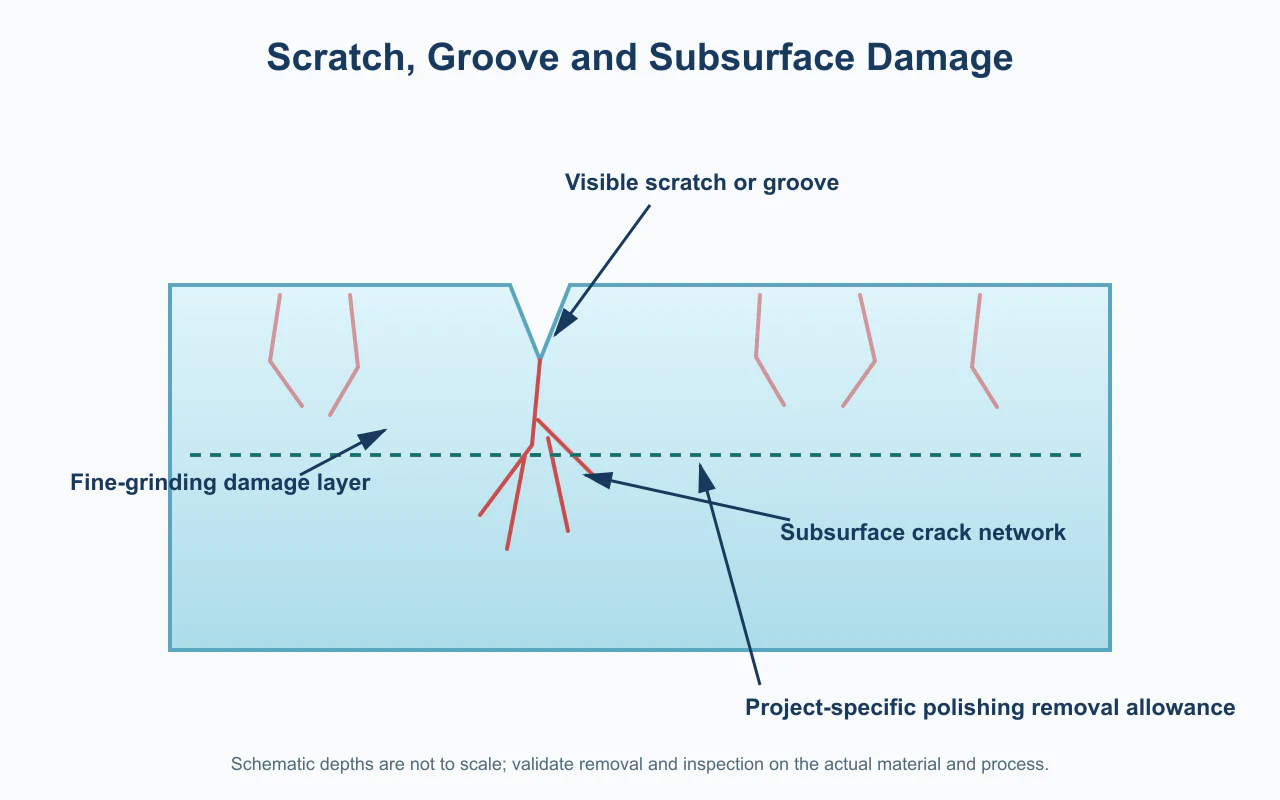
Hard abrasive contacts indent and cut the glass. Under many conventional conditions, cracks form around the contact zone and material is removed through brittle fracture. Coarse grinding removes stock efficiently; finer stages replace deeper damage with a shallower, more controllable layer.
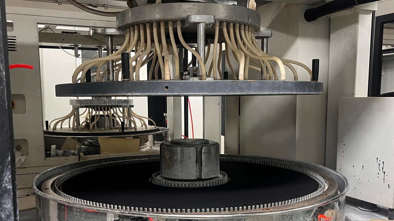
Loose and fixed abrasives behave differently
Loose-abrasive grinding is commonly treated as three-body wear because grains move between the workpiece and lap. Fixed diamond or other hard grains are bonded into a wheel, pellet or plate and behave more like two-body wear. Tool runout, feed direction, vibration and machine motion can produce directional texture.
Polishing controls the final surface
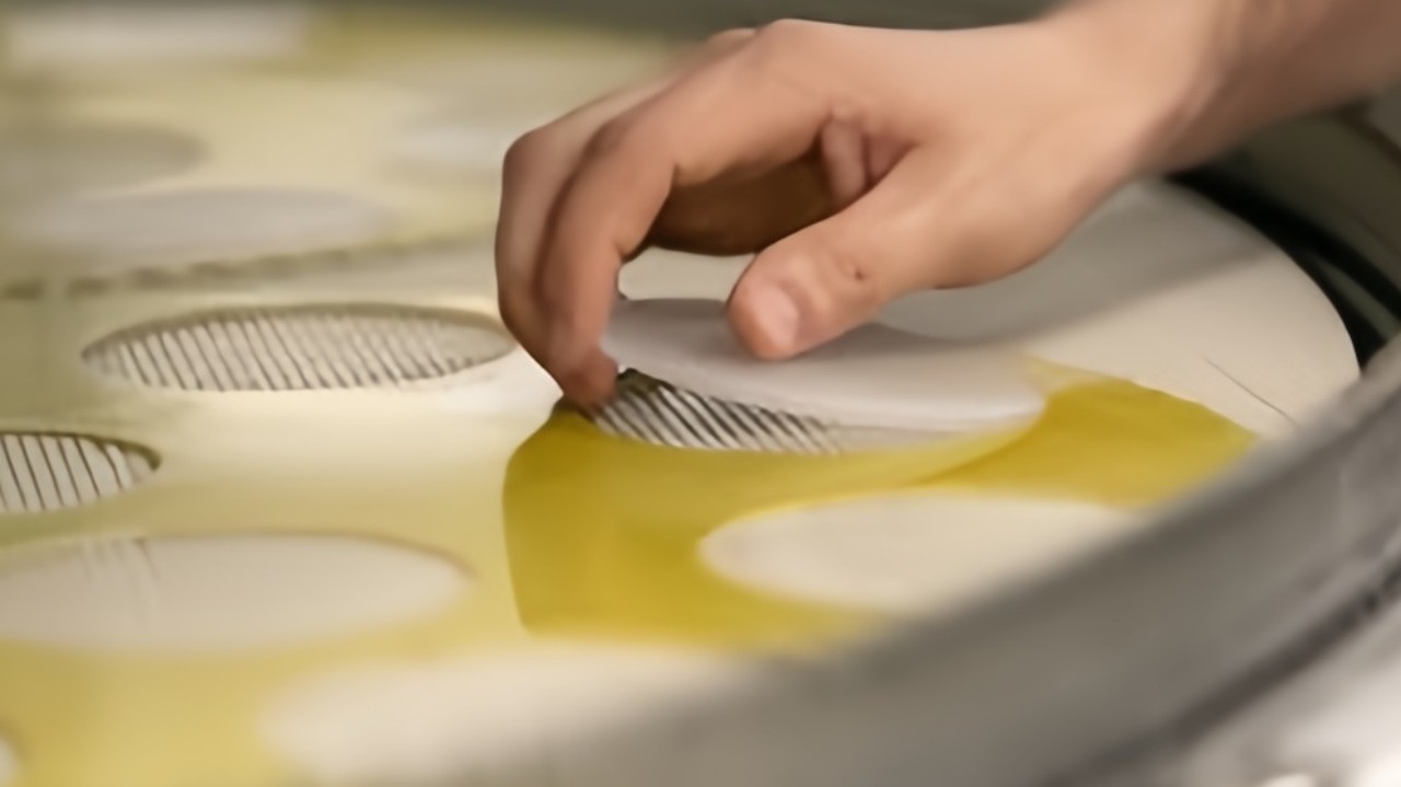
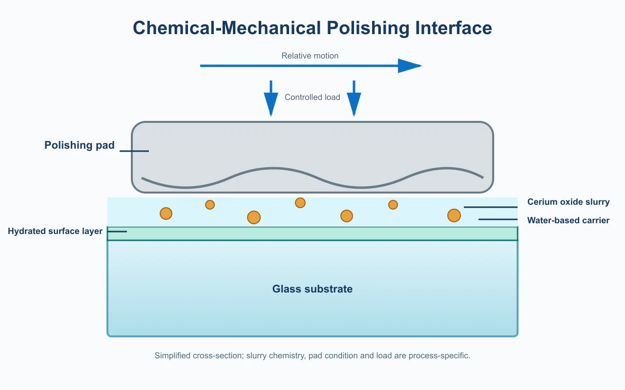
Glass polishing is generally understood as a chemical-mechanical process involving surface hydration, abrasive interaction and controlled material removal. Grains may remain mobile in slurry, become temporarily held by a pad or be fixed in a tool. Proper control minimizes additional brittle damage; contamination, local drying or excessive pressure can still introduce defects.
Flame polishing is a separate thermal process
Flame polishing briefly heats selected glass edges or formed surfaces so surface tension can smooth fine texture. It is not a substitute for precision optical polishing, can affect geometry and must be evaluated for glass composition, thickness, shape and residual stress. Processing is generally completed before tempering.
Typical Process Flow
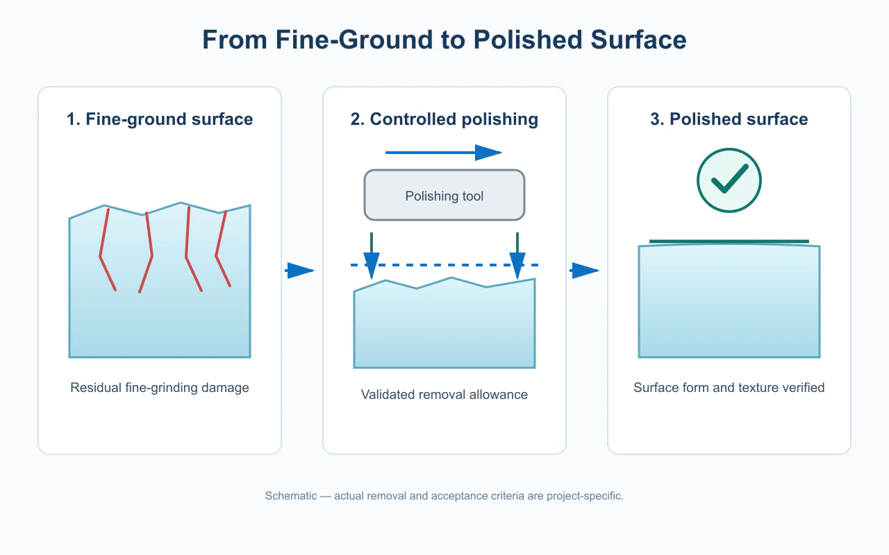
Each finer stage must remove the damage created by the preceding stage without carrying coarser particles forward. Separate tools, cleaning between stages and controlled slurry reduce residual scratches. Thin parts, curved surfaces, glass-ceramics and heat-sensitive assemblies may require a different route.
Supported Glass Materials and Components
Material and component examples help define the review scope; they are not blanket capability promises. Final feasibility depends on the drawing and required inspection method.
| Category | Examples for engineering review | Important review factors |
|---|---|---|
| Common silicate glasses | Soda-lime, float and low-iron glass | Starting flatness, thickness, optical use and later heat treatment |
| Heat-resistant glasses | Borosilicate compositions and glass-ceramics | Composition, thermal history, edge condition and material availability |
| High-performance glasses | Aluminosilicate, fused silica, quartz and selected optical glasses | Hardness, chemical response, contamination limits and metrology |
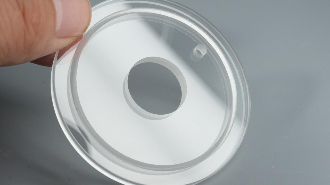
| Component forms | Windows, plates, wafers, discs, blocks and selected curved surfaces | Support, aspect ratio, clear aperture, edge zone and usable measurement area |
Achievable Tolerances and Surface Specifications
Surface finish levels
| Finish level | Typical intent | How to specify it |
|---|---|---|
| Ground finish | Geometry control, bonding preparation or a uniform matte surface | Dimensions, flatness, roughness range, edge condition and allowed grinding marks |
| Commercial polish | Appearance, transparency or functional sealing | Viewing condition, inspection zone, allowed defects and any roughness target |
| Optical polish | Controlled surface form, texture and optical performance | Clear aperture, surface form, roughness, imperfections, wavelength and test method |
| Superpolish | Application-specific ultra-low scatter or roughness | Material, parameter, instrument, bandwidth, scan area and functional surface zone |
Processing tolerances
| Characteristic | A complete requirement includes | Capability statement |
|---|---|---|
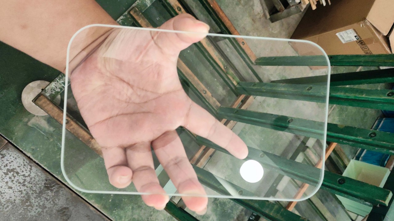
| Finished dimensions | Nominal size, tolerance, datum and edge allowance | Confirmed by material, thickness, geometry and part size |
| Flatness / surface form | Clear aperture, PV or RMS, wavelength, support state and allowed term removal | Confirmed with the applicable processing and measurement aperture |
| Parallelism / wedge | Datum surfaces, measurement locations and units | Confirmed after fixturing and thickness review |
| Surface roughness | Ra, Rq or other parameter, instrument, bandwidth, filtering and scan area | Confirmed for the selected glass and polishing route |
| Surface imperfections | Reference standard, clear aperture, illumination and acceptance level | Confirmed on the approved drawing or limit sample |
| Transmission | Material, thickness, wavelength range, polished faces and coating state | Evaluated separately from the polishing grade |
Abrasive selection
| Abrasive or tool family | Common role | Selection considerations |
|---|---|---|
| Silicon carbide | Loose-abrasive stock removal and grinding | Glass type, grain distribution, removal rate and downstream cleaning |
| Diamond | Fixed-abrasive wheels, pellets or precision grinding tools | Bond, grit, tool condition, coolant and risk of directional marks |
| Aluminum oxide | Fine grinding or selected polishing applications | Material compatibility, particle control and required finish |
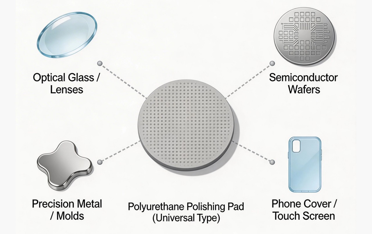
| Cerium oxide | Polishing many silicate glasses | Glass chemistry, slurry concentration, pH, filtration and pad condition |
| Zirconia or specialty abrasives | Material- or finish-specific polishing routes | Process validation, removal behavior and contamination requirements |
Equipment and maximum dimensions
| Equipment category | Typical use | How maximum size is confirmed |
|---|---|---|
| Single-sided grinder / polisher | Flat surfaces, figure correction and controlled polishing | Machine envelope, support, tool coverage and inspection aperture |
| Double-sided lapping / polishing | Parallel faces and thickness control | Carrier opening, part thickness, loading pattern and breakage risk |
| CNC fixed-abrasive equipment | Defined geometry, local removal and repeatable tool paths | Travel, fixture access, tool reach and collision clearance |
| Pitch or compliant-tool polishing | Selected precision optical surfaces | Material, curvature, usable aperture and metrology capability |
Quality Inspection Methods
| Characteristic | Typical inspection method | What the RFQ must define |
|---|---|---|
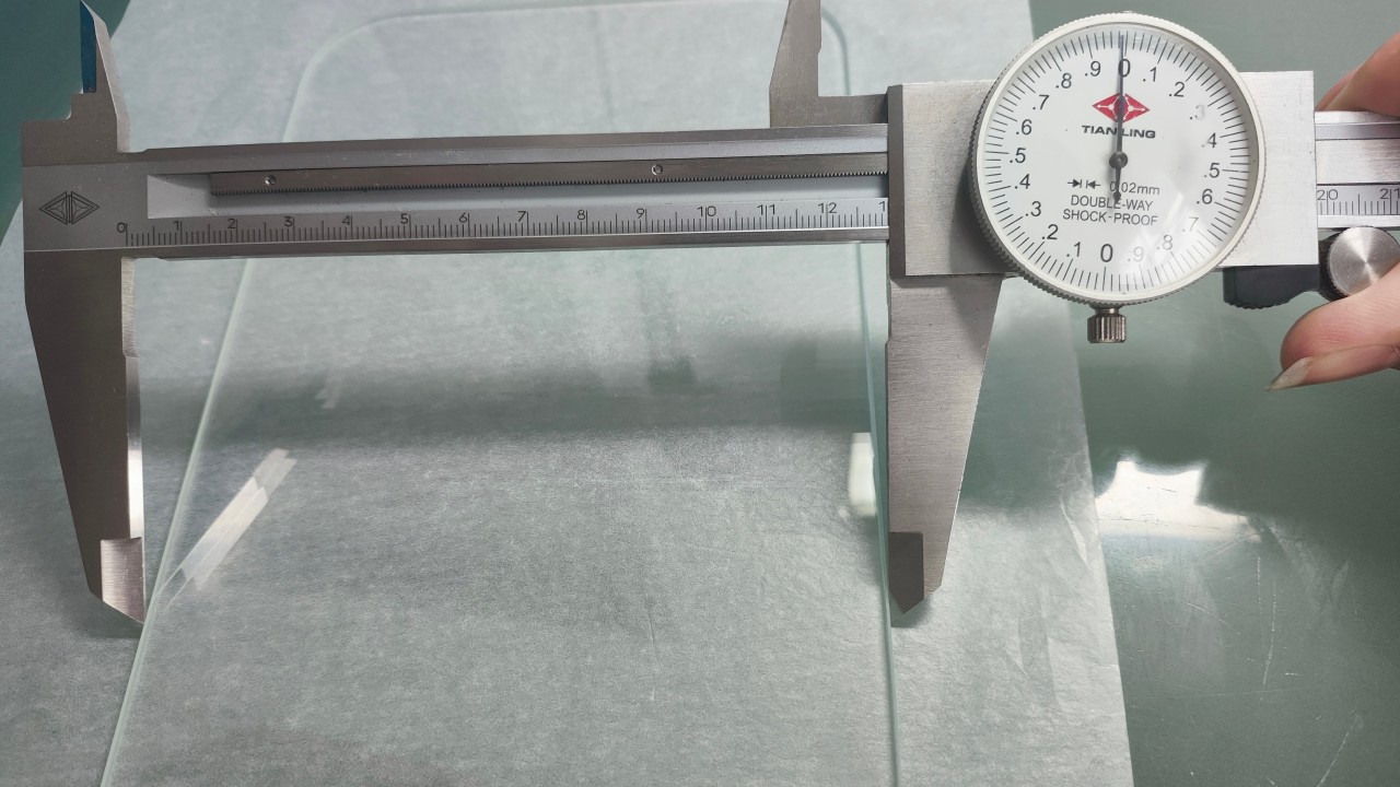
| Dimensions and thickness | Caliper, micrometer, height gauge or coordinate measurement as appropriate | Datum, measurement points, temperature and sampling |
| Flatness / surface form | Interferometric or mechanical measurement selected for the part | Wavelength, clear aperture, PV/RMS, support and allowed term removal |
| Surface texture | Contact or optical profilometry / microscopy as agreed | Parameter, bandwidth, filtering, scan size and number of locations |
| Surface imperfections | Controlled visual comparison or instrument-assisted inspection | Reference standard, illumination, viewing geometry and clear aperture |
| Transmission | Spectrophotometric measurement | Wavelength range, material, thickness, surfaces and coating state |
| Residual stress / damage | Polariscopic, destructive sample or validated process check where required | Acceptance method, sampling and whether the test is destructive |
| Lot acceptance | 100% inspection or an agreed sampling plan | Sampling standard, inspection level, AQL values and defect classes |
ISO 10110-7 can provide a framework for indicating optical surface imperfections, while ISO 10110-8 covers surface texture. The approved drawing should identify the applicable edition and agreed interpretation. Cleanroom classifications should only be published when the relevant controlled area is monitored or certified.
Common Defects, Causes and Solutions
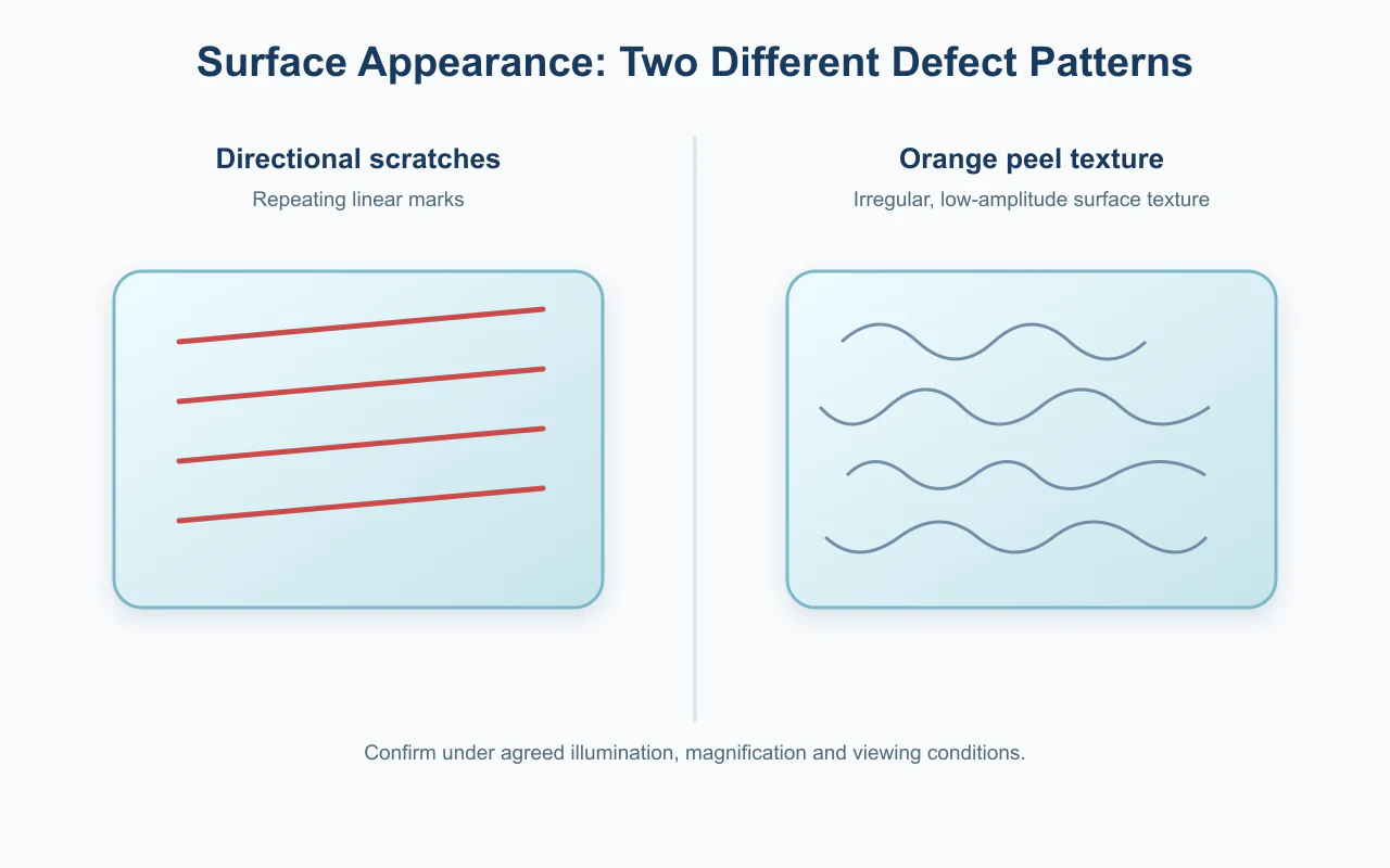
Scratches and directional marks
ProblemLinear marks remain visible or follow the machine motion.
Common causesCoarse-particle contamination, excessive abrasive step, tool damage, motion imprint or handling contact.
Corrective actionsSegregate abrasive stages, clean parts and equipment, filter slurry, condition tools and protect surfaces during handling.
Haze and incomplete polishing
ProblemThe surface remains cloudy or lacks uniform transparency.
Common causesInsufficient removal of the fine-ground layer, inactive slurry, unsuitable pad condition, poor wetting or nonuniform pressure.
Corrective actionsConfirm removal allowance, refresh and control slurry, restore pad condition and verify contact uniformity.
Orange peel and surface texture
ProblemA mottled, wavy or fine textured finish appears after polishing.
Common causesNonuniform local removal, excessive pressure or heat, unstable pad response, unsuitable slurry or a poor starting surface.
Corrective actionsStabilize pressure and temperature, condition the tool, improve fine grinding and validate slurry concentration and dwell.
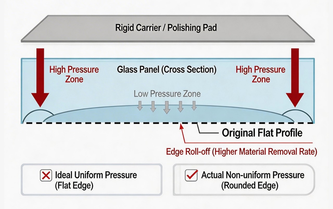
Edge roll-off
ProblemSurface form deteriorates near the edge or outside the usable aperture.
Common causesTool overhang, compliant pad behavior, excessive edge dwell or inadequate support.
Corrective actionsManage tool path and dwell, improve blocking or support, adjust compliance and define a realistic clear aperture.
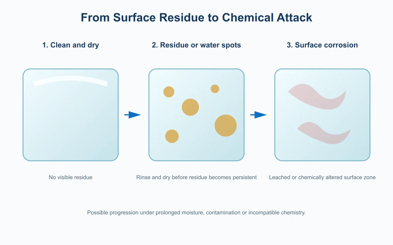
Surface stains and glass corrosion
ProblemResidue, water marks or chemically altered areas remain after processing.
Common causesDried slurry, unsuitable water chemistry, extended wet storage, fingerprints or incompatible cleaners.
Corrective actionsRinse promptly, validate water and cleaning chemistry, control drying and package only when surfaces are clean and dry.
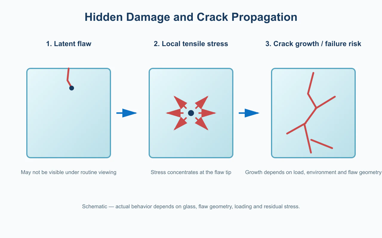
Residual stress and subsurface damage
ProblemStrength, stability or optical performance is affected by hidden damage or stress.
Common causesAggressive grinding, inadequate polishing allowance, poor support, local heating or an unsuitable process route.
Corrective actionsReduce loading, refine abrasive progression, validate removal on samples, improve fixturing and control temperature.
How to Select the Right Finish
| Application need | Starting process choice | Requirements to confirm |
|---|---|---|
| Safe handling or hidden technical surface | Ground finish may be sufficient | Edge safety, dimensions, roughness and allowed appearance |
| Visible transparent component | Commercial polishing | Viewing conditions, clarity, cosmetic limits and coating compatibility |
| Imaging, sensing or beam transmission | Optical polishing | Surface form, imperfections, texture, clear aperture and wavelength |
| Low-scatter or high-energy optical use | Project-specific superpolishing review | Material, roughness bandwidth, subsurface damage and contamination control |
| Decorative edge on compatible glass | Mechanical polish or separate flame-polish review | Geometry retention, stress, heat-treatment sequence and appearance |
Information Required for an RFQ
| RFQ item | Information to provide | Why it matters |
|---|---|---|
| Drawing and material | 2D drawing, 3D model if available, exact glass designation and permitted equivalents | Defines geometry and material-process compatibility |
| Surface specification | Form, roughness, imperfections, clear aperture and edge condition | Determines the process route and inspection workload |
| Optical requirements | Wavelength, transmission, coating state and functional surface | Prevents finish requirements from being separated from optical use |
| Inspection and records | Methods, sampling, first article and required reports or certificates | Aligns supplier and customer acceptance |
| Commercial details | Prototype and production quantities, target date, packaging and destination | Supports tooling, scheduling and shipping review |
BO-Glass Manufacturing Support and CTA
Packaging options
| Packaging need | Typical control | Information to confirm |
|---|---|---|
| Surface protection | Interleaving, protective film or noncontact separation selected for the finish | Coating state, allowable contact area and residue restrictions |
| Cleanliness | Final rinse, controlled drying and clean inner packaging as agreed | Particle, stain, ionic or cleanroom requirements |
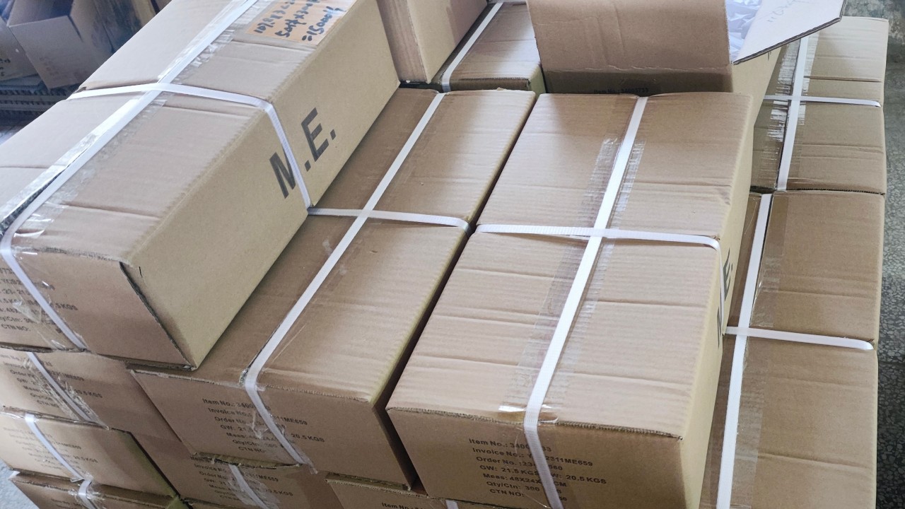
| Mechanical protection | Part separation, edge protection, trays, cartons or crates | Part mass, fragility, shipment method and handling orientation |
| Identification | Lot labels, part orientation and inspection-document linkage | Traceability, serial or lot requirements and label format |

Project workflow
Delivery is quoted after the process route, tooling, inspection workload, quantity and material availability are reviewed. Rework, replacement, return and liability terms follow the approved quotation, purchase agreement and quality terms.
Common purchasing questions
| Question | BO-Glass guidance |
|---|---|
| Can you quote from “optical polish” alone? | It is a useful starting point, but a production quotation needs measurable surface form, texture and imperfection requirements plus an inspection method. |
| Is sub-nanometer roughness available for every part? | No. Superpolishing is material-, geometry- and measurement-specific and must be reviewed using the required parameter, scan area, instrument and functional zone. |
| Can polishing alone correct flatness? | Polishing can influence figure, but the process normally establishes geometry during grinding and preserves it during polishing while controlling compliance and edge effects. |
| When should flame polishing be considered? | Only for selected compatible glass compositions and edge or formed-surface applications where the thermal effect on geometry and stress is acceptable. |
Standards and reference framework
These standards provide a useful specification framework; they do not replace the approved drawing, purchase specification or mutually agreed inspection plan. The applicable edition and acceptance criteria should be stated in the RFQ.
- ISO 10110-7:2017 — optical surface imperfections.
- ISO 10110-8:2019 — surface texture on optical drawings.
- ISO 2859-1:2026 — AQL-indexed lot-by-lot sampling by attributes.
- ISO 14644-1:2015 — airborne-particle cleanliness classification when a controlled environment is contractually required.
Related BO-Glass manufacturing capabilities
Pressed glass
Glassblowing
CNC machining and finishing
Heat and surface processing
Popular finishes
Related technical resources
Contact Us
Your feedback fuels our growth, and your questions drive our solutions.
We value your feedback, inquiries, and suggestions. Please feel free to get in touch with us
General inquiries
Please contact us via sales@bo-glass.com, and we will reply to you as soon as possible.
Interested to work with us
Drop your resume at info@bo-glass.com
and we will get back to you shortly.
We uses the contact information you provide to us to contact you about our relevent content, products, and services.