
Dimensions, Appearance and Testing
(1) Dimension requirements and measurement methods For rectangular flat tempered glass, its dimensions include side length and diagonal. The allowable deviations of side length and diagonal are shown in Table 3-19 and Table 3-20 respectively. The dimensions and allowable deviations of tempered glass of other shapes shall be agreed upon by the supplier and the buyer; the shape and quality of edge processing shall be agreed upon by the supplier and the buyer.
Table 3-19: Permissible Edge Length Deviation (Unit: mm)
| Glass Thickness (mm) | L < 1000 | 1000 < L < 2000 | 2000 < L ≤ 3000 | L > 3000 |
|---|---|---|---|---|
| 3, 4.5, 6 | +1 / -2 | ±3 | ±4 | ±5 |
| 8, 10, 12 | +2 / -3 | ±3 | ±4 | ±5 |
| 15 | ±4 | ±4 | ±4 | ±5 |
| 19 | ±5 | ±5 | ±6 | ±7 |
| > 19 | To be agreed upon by both supplier and customer | |||
(2) Round hole processing requirements Round hole processing is only applicable to tempered glass with a nominal thickness of not less than 4mm. The edge processing quality of the round hole shall be agreed upon by the supplier and the buyer.
① Aperture The aperture is generally not less than the nominal thickness of the glass, and the allowable deviation of the aperture shall comply with the provisions of Table 3-21. The allowable deviation of the aperture of holes less than the nominal thickness of the glass shall be agreed upon by the supplier and the buyer.
① Aperture The aperture is generally not less than the nominal thickness of the glass, and the allowable deviation of the aperture shall comply with the provisions of Table 3-21. The allowable deviation of the aperture of holes less than the nominal thickness of the glass shall be agreed upon by the supplier and the buyer.
Table 3-21: Hole Diameter and Permissible Deviation (Unit: mm)
| Nominal Hole Diameter (D) | Permissible Deviation |
|---|---|
| 4 ≤ D ≤ 50 | ±1.0 |
| 50 < D ≤ 100 | ±2.0 |
| D > 100 | To be agreed upon by both supplier and customer |
② Hole location
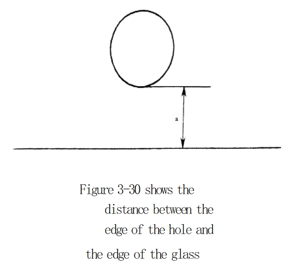
a. The distance between the edge of the hole and the edge of the glass should not be less than 2 times the nominal thickness of the glass, as shown in Figure 3-30.
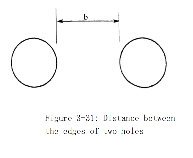
b. The distance b between the edges of the two holes should not be less than 2 times the nominal thickness of the glass, as shown in Figure 3-31.
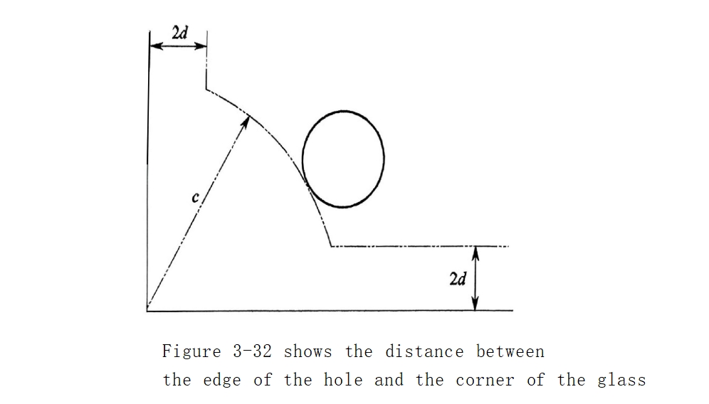
c. The distance c between the edge of the hole and the corner of the glass should not be less than 6 times the nominal thickness d of the glass, as shown in Figure 3-32. If the distance between the edge of the hole and the corner of the glass is less than 35mm, then the hole should not be in a symmetrical position relative to the corner. The specific position shall be agreed upon by the supply and demand parties.
c. The distance c between the edge of the hole and the corner of the glass should not be less than 6 times the nominal thickness d of the glass, as shown in Figure 3-32. If the distance between the edge of the hole and the corner of the glass is less than 35mm, then the hole should not be in a symmetrical position relative to the corner. The specific position shall be agreed upon by the supply and demand parties.
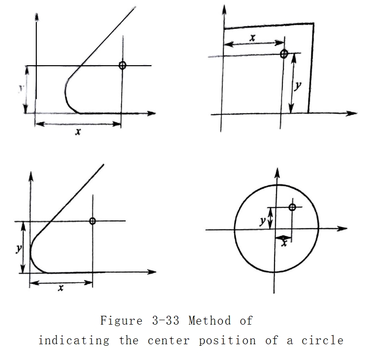
d. Method of expressing the center position of the circle and its allowable deviation. Establish a coordinate system as shown in Figure 3-33, and use the position coordinates (x, y) of the center of the circle to express the position of the center of the circular hole.
The allowable deviation of the center position (x, y) of the circular hole is the same as the allowable deviation of the side length of the glass (Table 3-19).
(3) Thickness requirements and measurement methods The allowable deviation of the thickness of tempered glass shall comply with the provisions of Table 3-22. For glass not specified in Table 3-22, the allowable deviation of its thickness may be the provisions of the thinner glass adjacent to it in Table 3-22, or it may be agreed upon by the supplier and the buyer.
Use an outside micrometer or an instrument of equivalent accuracy to measure at the midpoint of the four sides within 15 mm from the edge of the glass plate. The arithmetic mean of the measurement results is the thickness value. The unit is a millimeter (mm) and two decimal places are retained.
(3) Thickness requirements and measurement methods The allowable deviation of the thickness of tempered glass shall comply with the provisions of Table 3-22. For glass not specified in Table 3-22, the allowable deviation of its thickness may be the provisions of the thinner glass adjacent to it in Table 3-22, or it may be agreed upon by the supplier and the buyer.
Use an outside micrometer or an instrument of equivalent accuracy to measure at the midpoint of the four sides within 15 mm from the edge of the glass plate. The arithmetic mean of the measurement results is the thickness value. The unit is a millimeter (mm) and two decimal places are retained.
Table 3-22: Thickness and Permissible Deviation (Unit: mm)
| Glass Thickness (mm) | Permissible Deviation | Glass Thickness (mm) | Permissible Deviation |
|---|---|---|---|
| 3, 4, 5, 6 | ±0.2 | 15 | ±0.6 |
| 8, 10 | ±0.3 | 19 | ±1.0 |
| 12 | ±0.4 | > 19 | To be agreed upon by both supplier and customer |
(4) Appearance quality requirements and testing methods
① Appearance quality requirements The appearance quality of tempered glass should meet the requirements specified in Table 3-23.
① Appearance quality requirements The appearance quality of tempered glass should meet the requirements specified in Table 3-23.
Table 3-23: Appearance Quality Requirements
| Defect Name | Description | Permissible Defect Number |
|---|---|---|
| Edge Chipping | Each meter of edge length per glass piece may have chips no longer than 10 mm, with a depth extending from the edge toward the surface no greater than 2 mm, and extending into the thickness no greater than 1/3 of the glass thickness. | 1 chip |
| Scratches (Width < 0.1 mm) | Minor scratches less than 0.1 mm in width, permissible number per square meter. | Length ≤ 100 mm: 4 scratches |
| Scratches (Width ≥ 0.1 mm) | Scratches greater than 0.1 mm in width, permissible number per square meter. | Width 0.1 - 1 mm, Length ≤ 100 mm: 4 scratches |
| Clamp Marks | Clamp marks must be ≤ 20 mm from the glass edge, with edge deformation ≤ 2 mm (see Fig. 3-34). | 4 marks |
| Cracks and Missing Corners | Not permissible. | 0 |
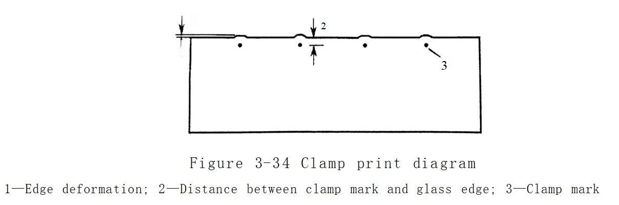
② Appearance quality inspection Use a steel tape measure with a minimum scale of 1mm for measurement. Put the sample on the cutting table and use a steel ruler to measure the distance between the edge burst the largest part of the clamp mark and the edge of the board, as shown in Figure 3-35.