
Borosilicate glass material overview
Internal Defects and Material Homogeneity in Molten-Formed Borosilicate Glass
An inclusion in a visible optical zone can distort the beam or stand out against a backlight. The same feature in a concealed region may have a different consequence. An internal-quality specification should identify the feature, its location, its optical effect and the conditions under which it will be judged.
Identify Bubbles, Striae and Solid Inclusions
| Observed feature | What to investigate |
|---|---|
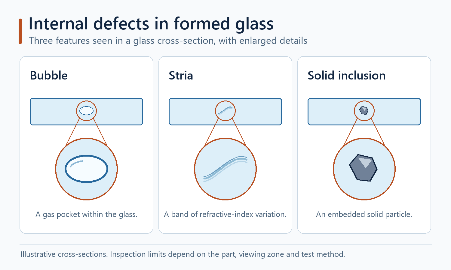
| Bubble or seed | Record its apparent size, shape, position and distribution. A seed is a small gas inclusion. Bubble populations can reflect the state of the melt, gas entrainment or local process conditions. |
| Stria or cord | Look for a band or streak that changes visibility with the viewing direction. Refractive-index variation can result from local compositional variation or incomplete mixing. |
| Stone or crystalline inclusion | Record the apparent particle and any surrounding distortion or crack. Undissolved batch, refractory particles and local crystallization are possible origins. |
Record the feature before assigning its cause. Light passing through a curved wall can magnify or obscure a feature. Rotate the part and examine it in reflected and transmitted light to distinguish a surface mark from a feature within the glass. SCHOTT optical glass catalogue, internal quality chapter
Relate Defect Distribution to Process History
Refining assists gas removal from the melt. Homogenization reduces local variation across the melt. Forming can stretch a region of compositional variation into a streak. If a feature appears across multiple moulds or tools, compare the affected pieces by melt lot and production time. If the feature repeats at the same position on one tool, examine the local flow, surface and tooling as well. Preserve samples and trace records so the proposed cause can be tested. BO-Glass melt preparation guide · BO-Glass defect troubleshooting guide
Set Inspection Zones and Viewing Conditions
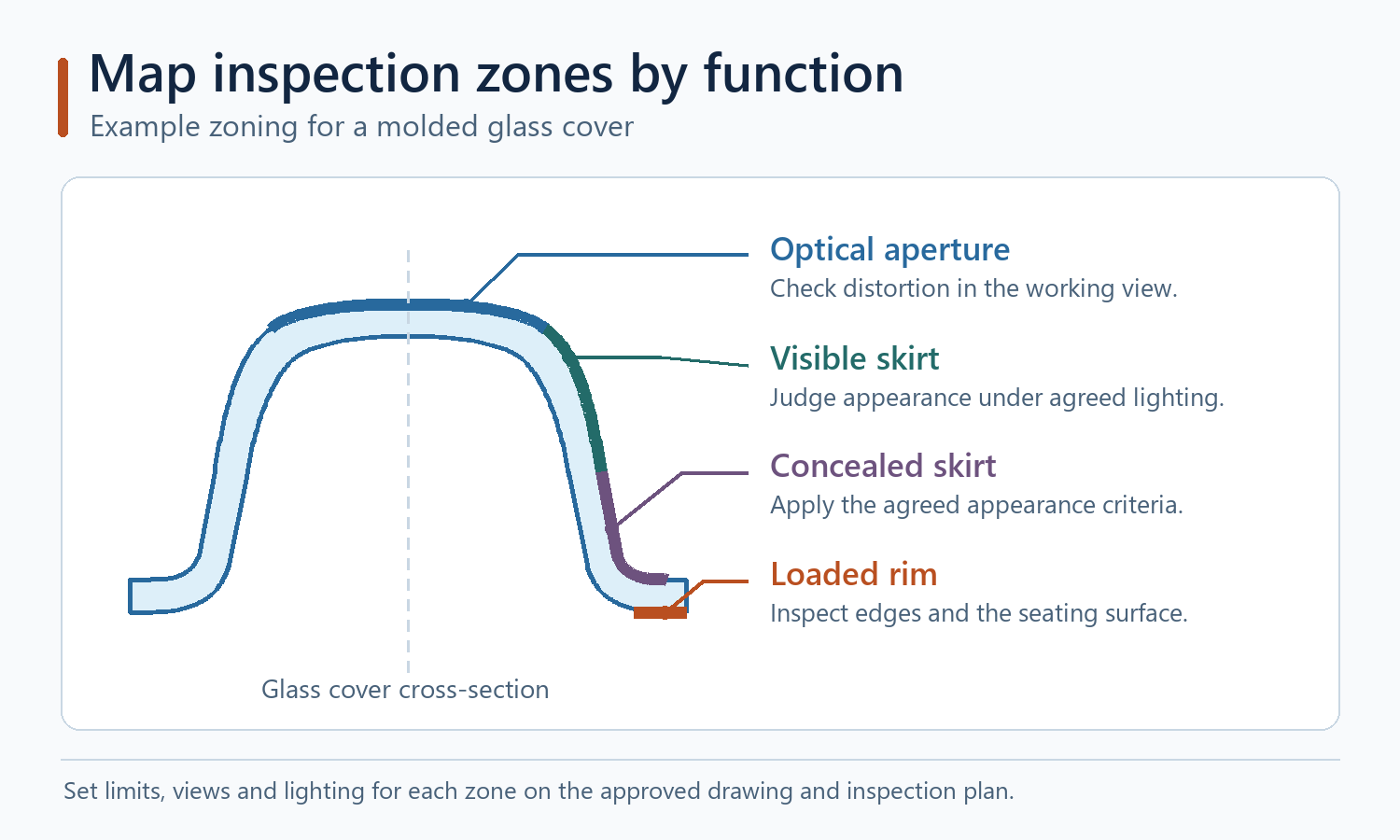
Mark the clear aperture, display face, concealed skirt and any structural interface on the drawing. Agree acceptable feature size, counting threshold, quantity, spacing or clustering for each relevant zone. Specify the lighting, background, orientation, viewing distance and magnification. A borderline reference sample can help inspectors reproduce the visual decision. For a precision optical function, discuss shadowgraph or wavefront testing where appropriate. Define the optical path and orientation so results can be repeated. SCHOTT TIE-25, Striae in optical glass
Inspection Priorities by Zone
| Functional zone | Pay particular attention to | Reproduce the inspection by defining |
|---|---|---|
| Clear aperture | Striae, bubbles in the light path and local image distortion | Aperture boundary, orientation and transmitted-light setup |
| Visible diffuser surface | Isolated spots, feature clusters and uneven lit appearance | Light source, viewing distance and approved appearance samples |
| Concealed skirt | Feature clusters near edges or adjacent to loading points | The boundary of the hidden area and the inspection conditions on each face |
| Loaded rim or seating land | Inclusions with nearby cracking and defects at the contact region | Loaded footprint, edge condition and the visual or magnified method |
Verify the Functional Effect
For a diffuser, evaluate visible spots under the intended light source and check whether the part produces the agreed light distribution. For a clear cover, assess distortion with the proposed viewing angle and useful aperture. Use the optical measurement guide to define the light source, viewing geometry and endpoint. A solid inclusion near a loaded rim merits separate review of cracking and structural risk. Recheck the original acceptance zone after any corrective trial and review nearby characteristics that the process change could influence.
References and Data Scope
SCHOTT’s optical-glass methods provide examples of how to define and measure internal quality. Establish acceptance limits for the finished borosilicate component using its actual geometry, application and agreed inspection capability.