
Environmental Reliability, Failure & Maintenance
Thermal, mechanical, chemical, weathering, contamination, coating, inspection, cleaning, and maintenance risks for aviation glass.
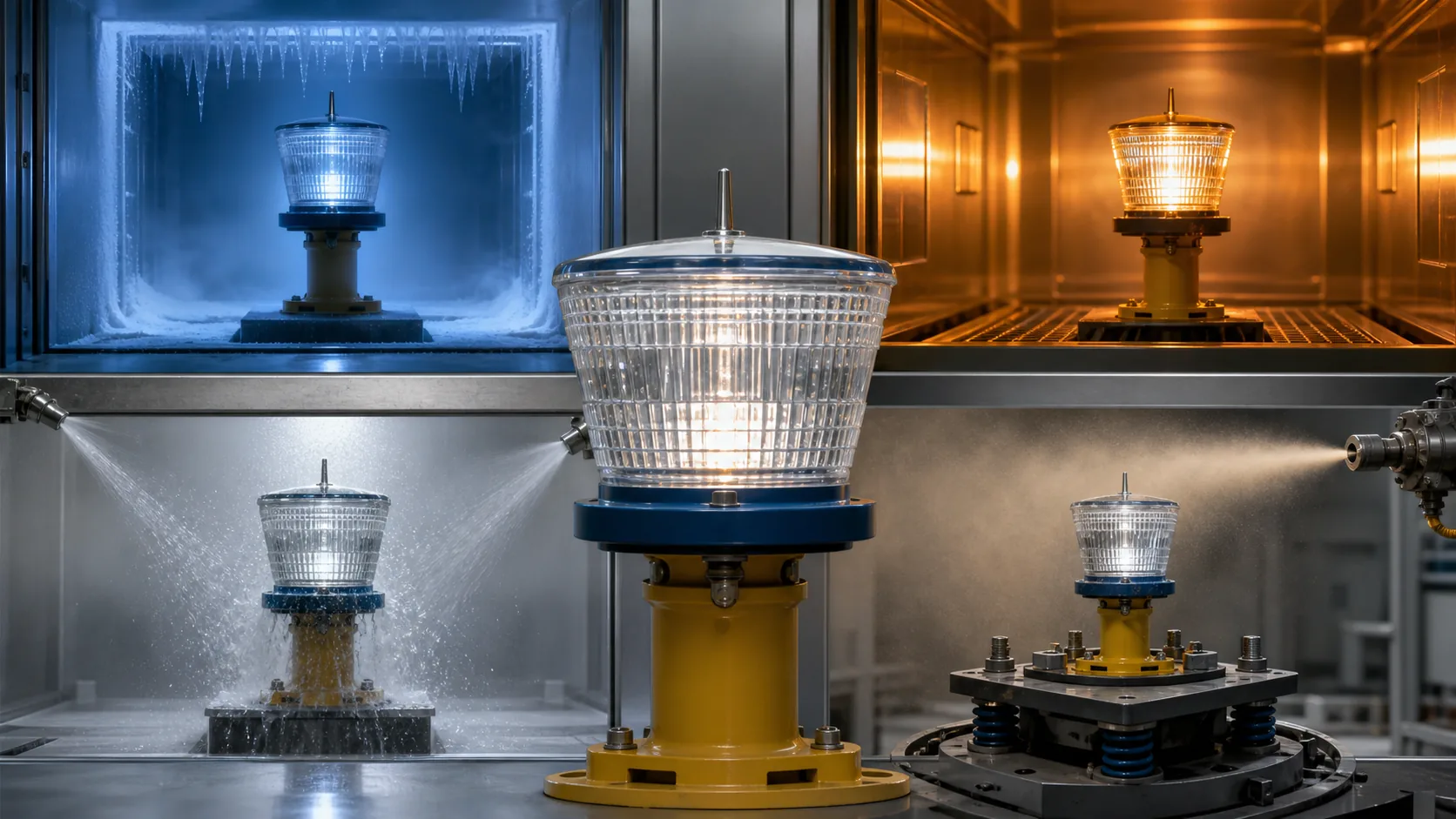
Environmental risk and acceptance matrix
A flat witness coupon, a finished glass component and a complete equipment configuration answer different questions. Select the specimen level that reproduces the relevant surface, edge, mounting, seal and functional optical path.
| Exposure | Representative specimen | Glass-component evidence | Complete-equipment acceptance |
|---|---|---|---|
| Temperature and thermal shock | Finished glass with the actual mounting interface | Edges, residual stress, dimensions and coating condition | Cracking, leakage, beam, color and alignment |
| Impact, static load and vibration | Actual supports, seals and retention | Chips, displacement and surface damage | Function, sealing, optical output and fastener condition |
| Sand, rain erosion and UV | Actual external surface and coating | Haze, transmission, pitting and adhesion | Beam, imaging or detector performance |
| Salt fog, cleaners and aviation fluids | Layered coupon plus finished component | Discoloration, peeling, corrosion and seal compatibility | Leakage and optical performance after exposure |
| Condensation and water ingress | Assembled sealed cavity | Dew point, seal lands and drainage condition | Cold start, humidity cycling and functional recovery |
| Field impact | As-installed part and associated hardware | Cracks, fragments and fracture origin | Alignment, output, sealing and return-to-service disposition |
Environmental and Mechanical Reliability
Reliability failures usually come from interactions rather than one weak material property. A temperature gradient acts through part thickness and mounting restraint; vibration becomes damaging near a structural resonance; salt or deicing fluid becomes more serious when a coating edge or seal is already vulnerable. This chapter explains those mechanisms first, then shows how a representative component or assembly test can answer the actual service question.
Thermal shock and temperature extremes
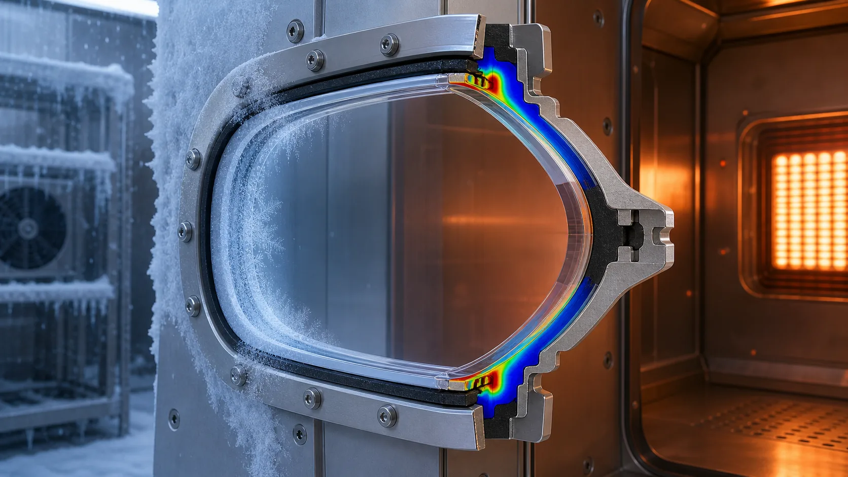
Thermal reliability is an assembly problem. Glass composition and CTE matter, but finished thickness, curvature, edges, residual stress, coating absorption, housing stiffness, seal behavior, heater location and transition rate determine the actual risk.
| Condition | Primary risk | Design input | Verification |
|---|---|---|---|
| Cold soak or start | Seal stiffening, CTE displacement and localized heater gradient | Minimum temperature, heater power, clearance and seal modulus | Functional testing from the cold-start condition |
| Hot operation | Source heat, optical absorption, coating stress and adhesive aging | Temperature locations, operating duration and obstruction condition | Beam, color, alignment and sealing after thermal stabilization |
| Hot rain or thermal shock | Rapid surface cooling and through-thickness temperature difference | Glass thickness, edge state and mounting restraint | Thermal shock on a representative mounted component |
| Repeated cycling | Accumulated stress, seal pumping and alignment drift | Temperature range, ramp rate, dwell and cycle count | Before-and-after optical and leakage comparison |
SCHOTT's BOROFLOAT thermal-shock data are a useful material-screening example: the reported 5% fracture-percentile result varies with sheet thickness and a defined water-quench method. It does not rate a molded prism, coated dome or mounted aerospace optic.
For covered airfield fixtures, FAA AC 150/5345-46F provides complete-fixture operating and storage conditions and includes a specific inset-light surface-temperature test. Its 160 °C limit belongs to that configured fixture test; it is not a universal glass temperature rating. Record temperatures at the source, filter, glass, frame and seal, then inspect cracking, coating, leakage, photometry and color in the relevant hot, cold and recovery states.
Impact, static load and vibration
Energy alone is not enough. A blunt pendulum, steel ball, hailstone, and sharp runway fragment can carry the same joules while producing very different contact stress. Support, strike location, temperature, edge condition, and mounting change the result as much as the material name.
FAA assembly example. AC 150/5345-46F requires a Type L-850 complete light to withstand repeated steel-ball impact at 29.5 ft·lbf (40 J). This is useful context for inset-light design, but it is not a generic 40 J rating for every loose prism or aircraft-light cover.
A meaningful component specification records:
- impactor mass, material, nose shape, energy or velocity;
- strike location, temperature, support, mounting, and number of impacts;
- production-representative edges, coatings, and prior conditioning;
- acceptance—no breakage, penetration, fragment release, leakage, optical damage, or functional loss.
The result is transferable only to configurations that preserve those conditions.
Common mistake: copying the FAA 40 J complete-fixture impact value onto a loose runway-light prism drawing. The housing, support ring, gasket, impactor geometry, and strike location are part of the test result.
The three loads answer different questions:
- Static load
- A relatively slow force reveals deformation, broad contact stress, and whether the housing carries load around the glass.
- Impact
- A short energy pulse creates local peaks and stress waves; flaw location and contact shape dominate.
- Vibration
- Repeated excitation reveals resonance, loosening, fretting, seal movement, and glass contact that may not appear in one load event.
For scale, FAA AC 150/5345-46F uses up to 15 g from 20–2,000 Hz for complete in-pavement fixtures, alongside the separate static, 11,000 lb shear, and 40 J impact requirements described above. Passing one exposure does not predict the others.
Testing the actual housing, seals, fasteners, source, and optic is important because a sequence can create hidden damage: vibration may loosen a retainer, impact may chip an edge, and a later leakage or thermal test may reveal the functional consequence.
Failure clue: a lens that survives a single impact but develops chips after vibration often has intermittent contact with a retainer. Increasing thickness may not help until that contact is removed.
Weathering, abrasion and water ingress
Outdoor exposure must reproduce the actual surface, coating, texture and cleaning route. A hard glass substrate can retain optical function while a softer coating, printed edge or seal interface fails first.
| Exposure | Likely damage | Record and control | Functional check |
|---|---|---|---|
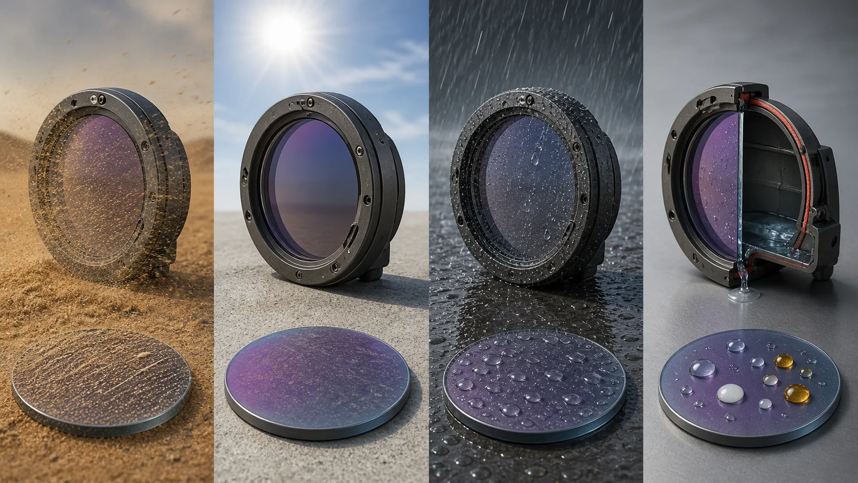
| Sand and dust | Micro-abrasion, blocked features, packed seal lands and scatter | Particle definition, velocity, angle, duration and dry-particle removal method | Haze, transmission, beam or image contrast before and after approved cleaning |
| Rain erosion | Pitting, coating wear and forward scatter | Drop or jet condition, speed, angle, temperature and exposed orientation | Surface inspection plus complete optical performance |
| UV and solar heating | Color shift, layer degradation, adhesion loss and thermal gradients | Spectrum, irradiance, temperature, humidity and duration | Transmission, chromaticity, adhesion and appearance |
| Water ingress | Condensation, corrosion, electrical leakage, dirt retention and freeze damage | Seal compression, cable entries, vents, drainage and pressure cycles | Leak test after vibration, impact and thermal exposure; inspect the internal condition |
Remove loose hard particles before wiping; otherwise maintenance can convert removable dust into permanent abrasion. Water can enter through seals, fasteners, cable penetrations, porous housings or pressure breathing even when the glass remains intact. Replacing a fogged lens without correcting the ingress path commonly produces a repeat failure.
Accelerated UV or weathering exposure supports a defined comparison or qualification condition. It should not be converted directly into a universal number of field years without a validated acceleration model.
Fluids, salt fog and coating durability
Use the fluid, concentration, temperature, contact pattern, wiping, rinse and recovery condition expected in service. One long immersion can miss damage caused by repeated short maintenance cycles.
| Exposure or indication | What it can reveal | Representative specimen | Acceptance evidence |
|---|---|---|---|
| Salt fog | Coating-edge attack, staining, crevice corrosion and seal-interface weakness | Coupon for film comparison; finished part and assembly for edges and crevices | Rinsed appearance, corrosion, adhesion, transmission and sealing |
| Fuel, hydraulic or deicing fluid | Swelling, softening, residue, color change and layer attack | Actual coating, ink, adhesive and seal stack | Optics, adhesion, dimensions and leakage after representative cycles |
| Approved cleaner | Abrasion, film residue, chemical attack and progressive wear | Finished texture or coating with the intended wipe material | Appearance, haze, spectrum and adhesion after the specified number of cycles |
| Peeling, haze or iridescence | Poor preparation, nonuniform deposition, moisture, stress or edge exposure | Witness coupon plus the actual curved and masked geometry | Microscopy or cross-section where needed, correlated with optical failure |
A flat witness coupon can show basic film stability but cannot reproduce curved-part deposition, recessed surfaces, edge coverage, metal retainers, galvanic couples or seal contact. Identify the specimen and configuration in every report. If a coating fails, compare a protected-surface location, revised stack, different cleaner or uncoated route against lifecycle and functional requirements rather than approving an appearance-only repair.
How is long-term reliability demonstrated?
Reliability evidence becomes stronger as the specimen represents more of the production configuration. Each level answers a different question.
| Evidence level | What it can answer | What it cannot prove alone |
|---|---|---|
| Material data | Initial candidate screening | Reliability after forming, finishing and mounting |
| Coupon test | Relative coating, ink or chemical compatibility | Curvature, edges and assembly interaction |
| Finished glass part | Geometry, edges, coating and process stability | Complete-equipment function |
| Mounted subassembly | Sealing, retention, CTE and contact interaction | All complete-equipment environmental qualification |
| Complete equipment | Configured optical, mechanical, sealing and functional performance | Untested configurations or arbitrary service life |
| Field feedback | Real contamination, maintenance and interaction patterns | Universal conclusions without controlled configuration and records |
A reliability plan records the tested configuration and drawing revisions, sample count and production representativeness, test sequence and preconditioning, optical and leakage data before and after exposure, acceptance limits, anomaly and retest rules, and batch and change traceability. Track functional drift—not merely survival.
Use a justified sequence where service stresses interact. Vibration may relax a retainer, thermal cycling may pump moisture past the seal, and a later leakage or optical test may reveal the combined weakness. Separate pristine specimens can each pass one exposure while never reproducing that sequence. Accelerated cycles must not be converted into calendar life without a validated model.
Failure Modes, Inspection and Maintenance
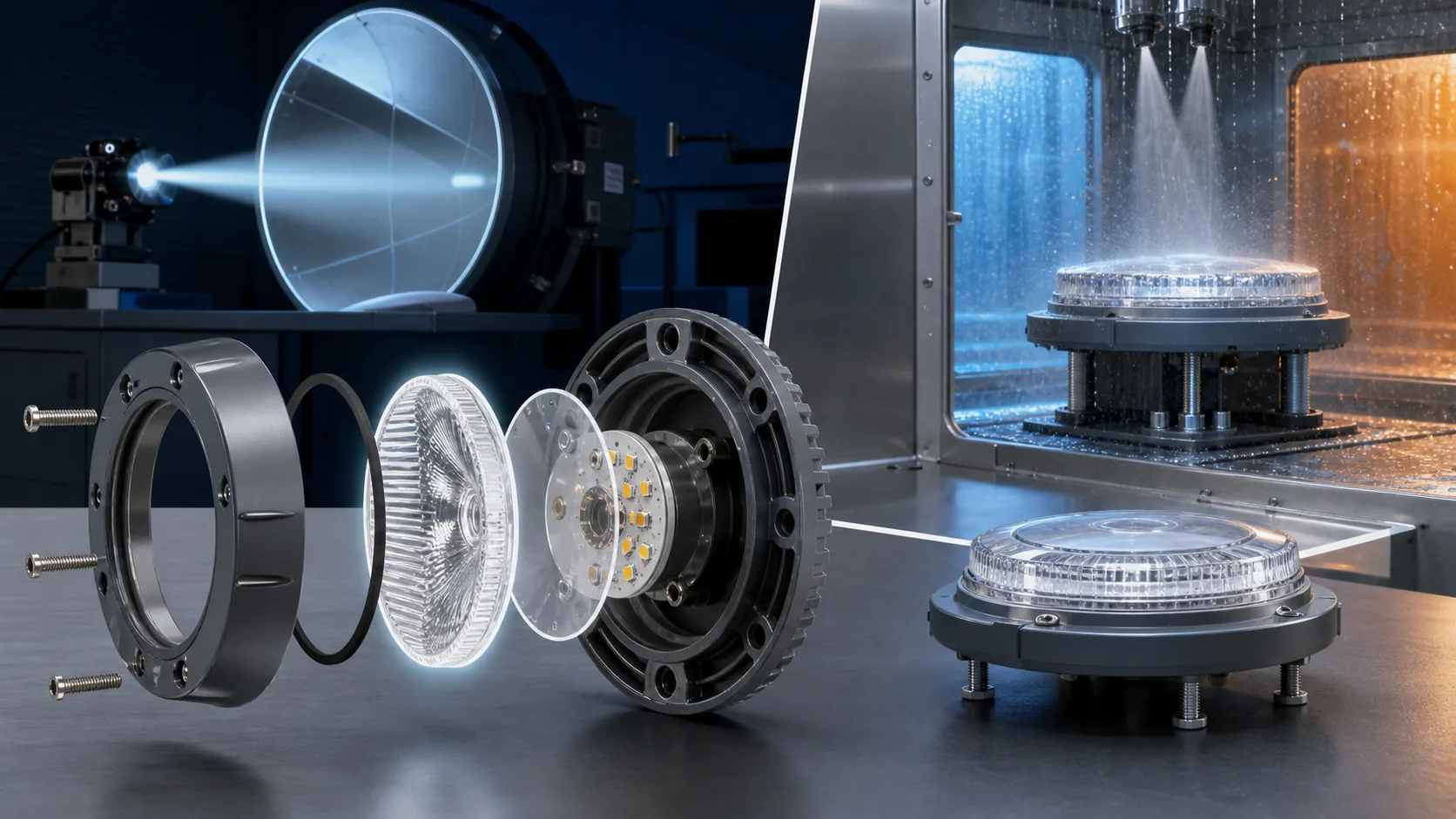
A scratch, chip, haze patch, or color change is not equally important everywhere on a glass component. Its significance depends on location, growth, optical zone, sealing function, and the light or sensor task. The aim of inspection is therefore to understand what the indication means, not merely to count defects. These questions link visible symptoms to likely causes, functional risk, cleaning limits, and replacement decisions.
Visible defects and disposition matrix
Do not create universal crack, chip or scratch limits from this guide. Measurable acceptance and repair limits belong in the controlled drawing, aircraft AMM/CMM, equipment manual or approved maintenance data.
| Finding | Primary risk | Inspect | Disposition authority |
|---|---|---|---|
| Crack | Growth, pressure loss, fragments and functional loss | Origin, depth, loaded zone and seal area | Approved maintenance data or design authority |
| Edge chip | Reduced strength and sealing failure | Clamp zone, hole edge, contact point and seal land | Drawing or approved repair limit |
| Scratch or pit | Scatter, stray light and image degradation | Optical zone, depth and functional effect | Applicable optical acceptance standard |
| Coating peel or haze | Transmission or spectral drift | Surface side, area, adhesion and environmental history | Product specification and responsible authority |
| Internal condensation | Ingress, corrosion and contamination | Seals, cable entry, drainage and dew-point condition | Complete-equipment maintenance procedure |
| Color or output drift | Loss of signal margin or coverage | Spectrum, temperature, drive, filter and complete-light chromaticity | Equipment acceptance requirement |
Clean only by an approved method before classifying a surface indication. Record photographs with scale, optical zone, loaded edge, seal land, operating history and environmental condition. Never polish a suspected crack or blend a chip unless approved repair data define the method, remaining dimensions and reinspection. Repeated damage at one clock position should trigger inspection for a burr, distorted retainer, hard contact, uneven gasket compression or packaging problem.
Condensation and color-shift diagnosis
Classify the symptom before selecting corrective action.
| Observed symptom | Likely paths to investigate | Confirm with |
|---|---|---|
| External dew | Surface temperature below ambient dew point | Surface temperature, humidity and operating state |
| Internal condensation | Ingress, trapped assembly moisture, vent or purge failure | Leak/pressure-decay test, internal dew point, seals, drainage and cable entries |
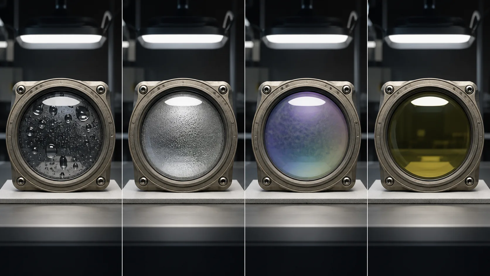
| Haze remaining after cleaning | Micro-abrasion, internal contamination or permanent layer damage | Controlled illumination, haze/transmission and surface inspection |
| Coating fog or iridescence | Layer attack, delamination, stress or nonuniform film | Surface-side identification, adhesion, spectrum and microscopy where needed |
| Measured chromaticity change | LED, filter, coating, temperature or incorrect replacement configuration | Source spectrum, glass transmission and complete-unit chromaticity |
| Apparent color change with lower output | Contamination, source aging or intensity reduction | Cleaned output, photometry and chromaticity under the same conditions |
| Change after LED bin, drive or temperature shift | Source-filter spectral mismatch | Manufacturer/type/bin, current, temperature and permitted configuration |
A heater clearing the window does not prove that the enclosure is dry, and cleaning the surface does not prove that the underlying coating remains within specification. Use controlled substitution only when the design permits it, and do not pair an off-nominal filter with a drifting source to create an uncontrolled matched set.
Post-impact inspection and root-cause analysis
Follow the aircraft maintenance manual, airport procedure or equipment manual for the event. An intact transparent surface does not prove that the reflector, housing, gasket, fasteners, wiring or optical alignment behind it remain serviceable.
- Contain and isolate. Protect personnel and equipment, quarantine affected parts and follow event-specific operational instructions.
- Preserve the as-found state. Photograph installation, fragments, contacts, seals, contamination, orientation and associated hardware before cleaning or disassembly.
- Build failure hypotheses. Reconstruct part identity, lot, hours, maintenance, weather, impact and assembly history.
- Examine the evidence. Use fracture, dimensional, material, coating and assembly inspection to test plausible causes rather than assuming the bulk glass was weak.
- Confirm root cause and contributors. Separate the initiating event from point contact, damaged edges, seal load, thermal state or process variation.
- Define corrective action. Address the relevant drawing, edge process, mold, coating, gasket, torque, packaging, training or inspection control.
- Verify on a representative configuration. Repeat the critical exposure and functional acceptance with production-representative hardware.
- Monitor later lots and field units. Track recurrence, effectiveness and any configuration-dependent pattern.
Do not clean, polish, separate or mix fragments before photography and records are complete. Sending only broken glass to a laboratory without the housing, seals, retention condition and installed orientation is usually insufficient to identify root cause. Return-to-service remains a complete-equipment decision under the applicable approved maintenance data.
Official and standards references for this guide
Source status was reviewed on August 12, 2026. The contract, certification basis, approved equipment configuration and controlled document revision determine actual applicability. Obtain authorized copies of paid standards.
- FAA, AC 150/5340-26C - Maintenance of Airport Visual Aid Facilities, active on the review date, for applicable airport-light cleaning, water, inspection and maintenance guidance.
- FAA, AC 150/5345-46F only for environmental and mechanical requirements of the covered complete airfield-fixture configurations.
- RTCA, DO-160. RTCA identifies DO-160G as the current published version on the review date; program-selected sections and categories apply to airborne equipment, not ground airport lighting.
- FAA, AC 43-217 - Anticollision Light Maintenance Program, active with a June 23, 2026 editorial update; its scope is aircraft anticollision-light maintenance rather than all aviation glass.
Contact Us
Your feedback fuels our growth, and your questions drive our solutions.
We value your feedback, inquiries, and suggestions. Please feel free to get in touch with us
General inquiries
Please contact us via sales@bo-glass.com, and we will reply to you as soon as possible.
Interested to work with us
Drop your resume at info@bo-glass.com
and we will get back to you shortly.
We uses the contact information you provide to us to contact you about our relevent content, products, and services.