
Cockpit Display Glass & Aerospace Optical Windows
Cover glass and optical windows for cockpit displays, instruments, sensors, cameras, and protected aerospace optical paths.
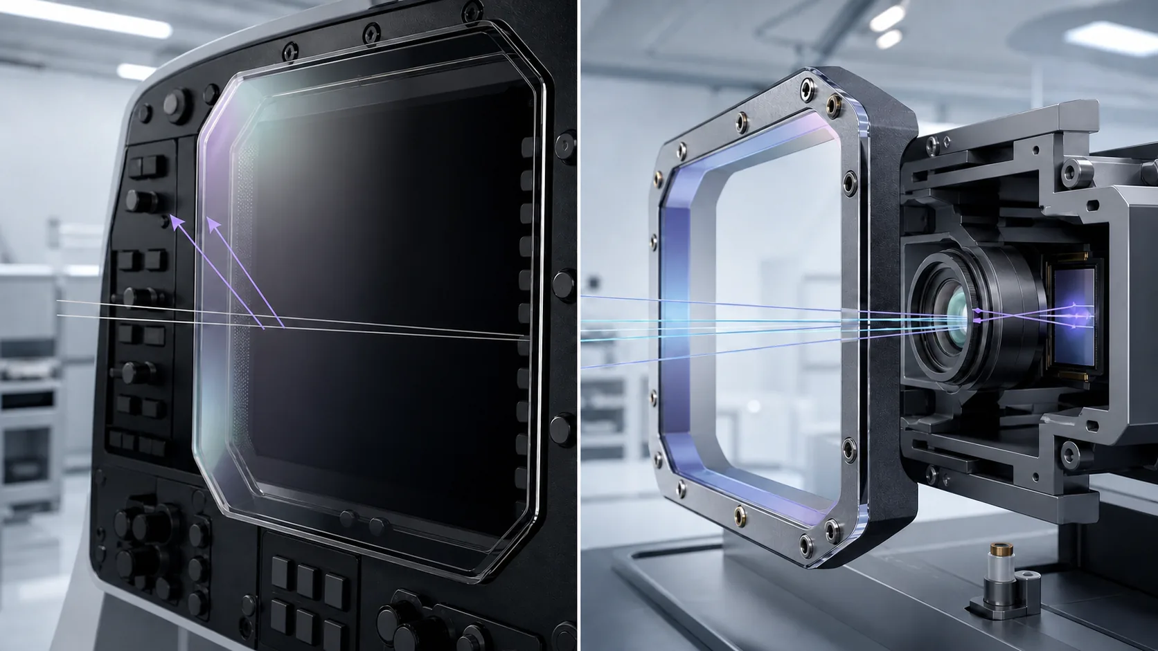
Application and complete-system acceptance guide
Use the application first to identify the optical characteristic that matters, then separate finished-component evidence from the verification that belongs to the installed display, camera or sensor.
| Application | Core component characteristics | Primary risks | Complete-system acceptance |
|---|---|---|---|
| Cockpit display cover | Reflection, haze, polarization and masks | Glare, ghost images and stress-birefringence color patterns | Readability under representative ambient light and viewing angles |
| Analog instrument window | Wedge, distortion and reflection | Pointer parallax and scale obstruction | Accurate reading over the required viewing envelope |
| Visible or NIR camera window | Spectral band, transmitted wavefront and wedge | Focus loss, MTF reduction and ghosts | Image quality and line-of-sight verification |
| Laser or ranging window | Spectrum, incidence angle and surface quality | Back reflection and ranging bias | Configured transmit-and-receive optical-path testing |
| External sensor window | Sealing, heating and coatings | Condensation, rain erosion and contamination | Detector performance after the defined environment |
Specification input and acceptance matrix
Do not copy generic optical tolerances into a cockpit cover or sensor-window drawing. Define the system input, then select a measurable component characteristic and an acceptance method that represents the installed viewing or detector path.
| Specification input | Define on the project | Acceptance evidence |
|---|---|---|
| Wavelength range and incidence angle | Operating spectral band, source or detector response, nominal and maximum field angle, temperature where relevant | Spectral transmission or reflection data at agreed angle, temperature and polarization state |
| Clear optical aperture | Usable viewing or sensing area, excluded edge zone, mask boundary, datum and mounted obstruction | Drawing inspection plus illuminated clear-aperture verification in the intended mounting orientation |
| Transmission, reflection and haze | Target quantity, wavelength or illuminant, viewing geometry, coated surfaces and allowable non-uniformity | Calibrated measurement with method, aperture, background, instrument geometry and result recorded |
| Wedge, parallelism and transmitted wavefront | Allowable line-of-sight shift, ghost position, image distortion, focus effect and orientation key | Autocollimation, interferometry, grid-distortion or system-imaging test under the stated support condition |
| Polarization and residual stress | Display polarizer orientation, acceptable luminance or color change, stress-birefringence limit and bonded condition | Polarized inspection or retardation measurement correlated with the actual display and viewing angles |
| AR, AG and other surface treatments | Coated side, spectral and angular design range, residual color, texture, adhesion and cleaning exposure | Coating witness data plus finished-part reflectance, haze, appearance and durability checks |
| Mounting, sealing and heating | Seats, gasket, retainer load, adhesive, edge clearance, heater pattern, connector and thermal path | Free-state component inspection followed by installed optical, leakage and thermal verification where applicable |
| Condensation condition and method | External humidity, internal dew point, cold soak, altitude or pressure, power-off state, warm-up time and purge strategy | Production-representative assembly test recording surface temperature, fogging location, duration and optical recovery |
Cockpit Instruments and Avionics Displays
Cockpit glass can be perfectly transparent and still make a display harder to read. Reflections, double images, haze, surface scatter, coating color, fogging, and viewing angle all influence how quickly a pilot can interpret information. The questions here connect those visual effects with glass thickness, surface treatment, bonding, lighting conditions, and inspection methods, helping teams choose specifications that protect readability rather than transparency alone.
What does cockpit instrument glass need to achieve?
Cockpit display covers and instrument windows protect safety-related information while preserving accurate, rapid reading in daylight, darkness, dimmed operation and off-axis viewing. Relevant characteristics can include reflection, transmission, haze, distortion, polarization, residual stress, scratch resistance, cleanability, masks, touch functions, heaters and conductive coatings.
Specify the complete viewing stack: display type and luminance, source spectrum, polarizer, cover, air gap or optical bond, viewing envelope, cockpit ambient light, representative eyewear, cleaning agents, mounting and environmental conditions. A loose cover that meets transmission or flatness limits can still create glare, double images, color shift or unreadable symbology after assembly.
FAA AC 25-11B provides guidance for applicable Part 25 electronic flight-display systems, while SAE AS8034C addresses installed electronic displays within its stated scope. Neither document independently qualifies a cover glass. The display applicant and aircraft approval owner determine applicability and obtain system-level evidence using the controlled production configuration.
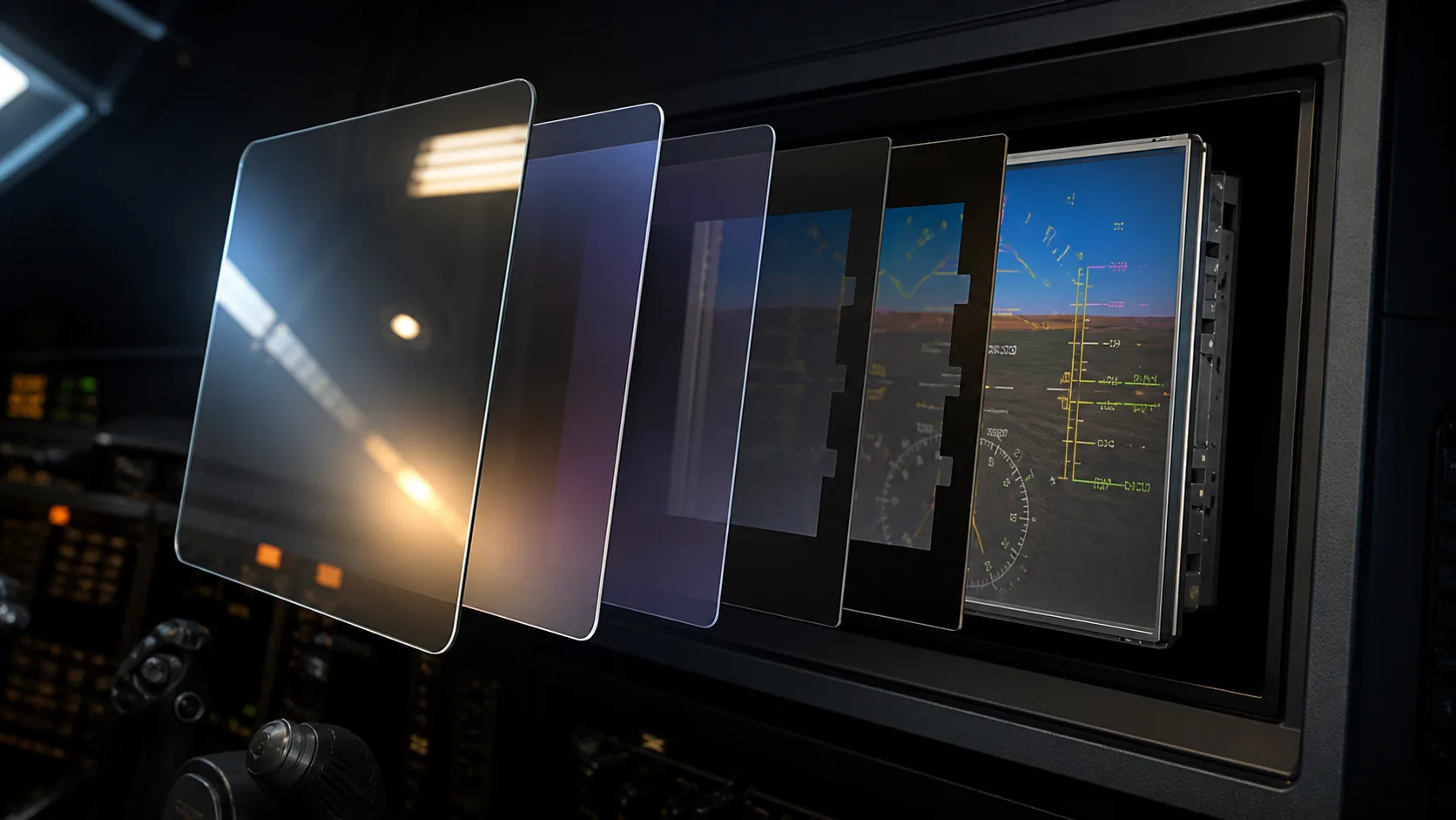
Reflection, glare and cockpit readability
Anti-reflective and anti-glare treatments solve different cockpit viewing problems. An AR thin-film stack reduces Fresnel reflection over a defined wavelength and angle range, helping preserve contrast and image sharpness. An AG texture spreads mirror-like reflections and can hide fingerprints, but excessive texture adds haze, sparkle and resolution loss. A combined treatment is useful only when the finished display still meets contrast, color, resolution and cleaning requirements.
Evaluate AR, AG and optical bonding with the actual display, polarizers, air gap, masks, cockpit lighting and certification viewing envelope. Optical bonding can remove reflective interfaces but introduces adhesive aging, rework, thermal-expansion and stress considerations. Installation angle and surrounding bright structure can matter as much as normal-incidence reflectance.
Specify coated side, spectral and angular range, luminous reflectance, haze, gloss or texture, residual color, cosmetic zones and durability method. Validate powered and unpowered appearance at relevant brightness settings, ambient-light directions, viewing angles and polarized-eyewear orientations. This section controls human readability; wedge, boresight and detector ghost paths for sensor windows are treated separately below.
Distortion, polarization and residual stress
The appropriate limit depends on display size, pixel pitch, viewing distance, air gap, curvature, and the information shown. A general flatness value may not predict visual distortion. Local slope and transmitted wavefront can matter more than total bow, while a curved cover may be intentionally powered. For analog gauges, parallax and pointer readability may dominate.
Define an application-level criterion first: symbol displacement, grid distortion, focus change, or wavefront error over the viewing aperture. Then select a measurable component control such as flatness, transmitted wavefront, optical power, wedge, or grid distortion. Separate the clear aperture from the bonded or clamped perimeter. Measure in a free state and, if mounting can distort the part, in an installed condition. Thin glass can conform to a warped frame, so tightening free-state flatness alone may not solve the issue. Use a visual master for cosmetic quality, but retain quantitative metrology for functional distortion. The tolerance should protect readability without forcing imaging-grade cost where the display does not need it.
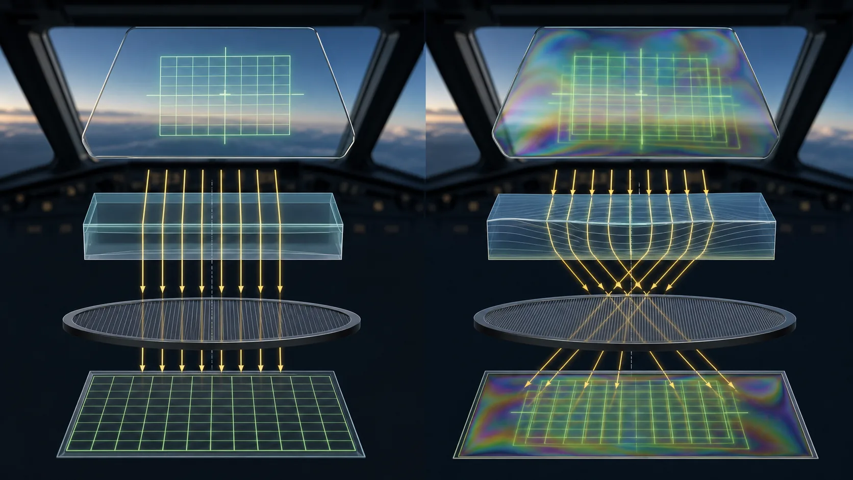
- Residual or mounting stress can make glass birefringent, changing the polarization state of transmitted light. With polarized LCDs, sunglasses, or other optical elements, this can create color fringes, dark areas, or viewing-angle changes. Some coating stacks and adhesives also interact with polarization.
- Thermal strengthening, chemical strengthening, bending, edge stress, uneven bonding, and clamp load can all influence retardation. The effect must be evaluated with the actual display polarization and representative sunglasses or visors where required. A part that looks clear in unpolarized inspection may show patterns in service.
- Specify allowable optical retardation or a polarized inspection method when the risk is real. Control process uniformity and mounting stress. Rotate the display and viewer through relevant angles during validation. Do not assume low residual stress is always required; chemically strengthened glass intentionally contains stress. The functional question is whether the stress distribution causes unacceptable optical behavior in the configured system.
What does NVIS compatibility mean for cockpit glass?
NVIS compatibility means cockpit lighting and displays are controlled so they remain usable to the crew without degrading the performance of night-vision imaging systems. It is not a generic dark tint. Filter glass or coatings shape spectral radiance in bands to which the goggles are sensitive while preserving readable visible color and luminance for unaided viewing.
Requirements depend on the aircraft, equipment, NVIS class, display type, and program standard, such as applicable military or civil guidance. The glass must be designed with the source spectrum and complete display stack. Thickness variation, filter composition, coating, and temperature can change performance. Color balance and daytime readability must also be evaluated. Specify the controlling NVIS standard and measured quantities, not simply “NVG green.” Use calibrated spectral-radiance measurements on the complete equipment at required dimming states. A material transmission curve alone is insufficient because the emitted spectrum and display drive determine compatibility. Maintain lot and thickness controls for filter glass and re-evaluate any source, coating, or supplier change.
Cleaning durability, legends and masks
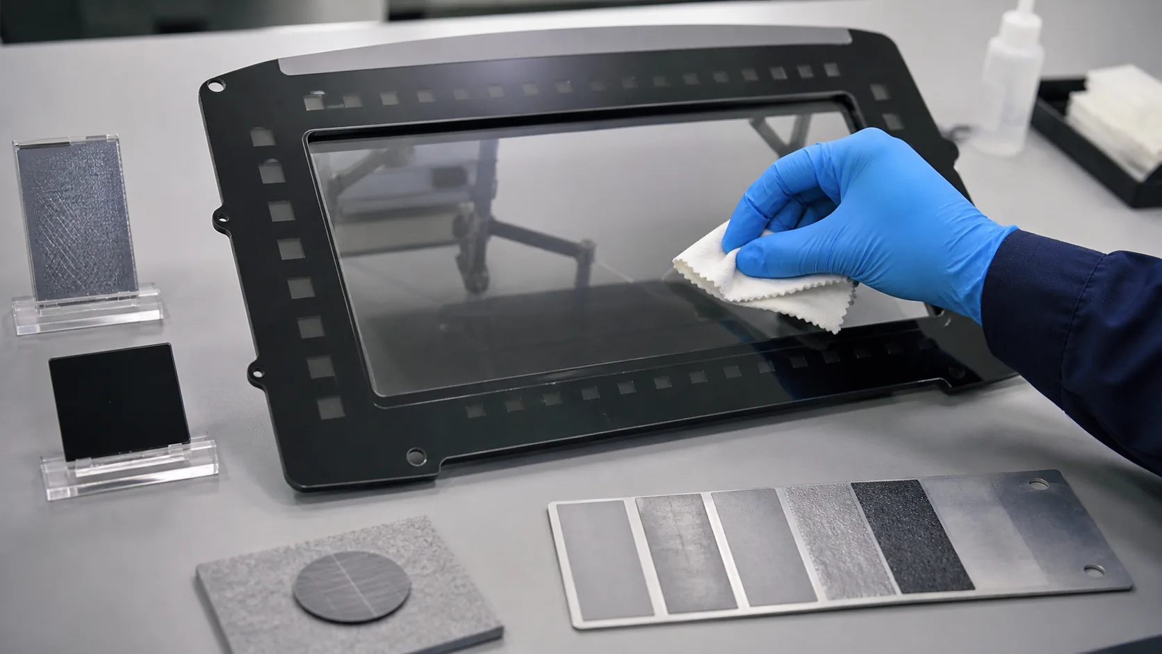
Cleaning, coating and printed-mask controls should represent the finished surface and actual maintenance process rather than a generic hardness claim.
| Control | Define on the project | Acceptance after exposure |
|---|---|---|
| Cleaning cycle | Approved chemical, wipe, pressure, dry-particle condition, dwell and cycle count | Reflectance, transmission, haze, color, readability and visible damage |
| Coating durability | Surface location, adhesion method, abrasion method and cosmetic zones | No unacceptable delamination, scratches, glare or touch-function change |
| Mask and legend opacity | Artwork revision, color, thickness, pinholes, edge definition and light-blocking target | Transmitted- and reflected-light inspection plus installed luminance where illuminated |
| Registration and process order | Functional datums, printing sequence, bending or strengthening sequence and cure limits | Alignment to the display, aperture and mounting features |
| Seal-land compatibility | Ink, coating, adhesive, gasket and cleaning-fluid interaction | Retention, compression, leakage and optical inspection after environment |
Use representative finished parts for qualification; witness coupons can support process monitoring but cannot reproduce mask edges, curved geometry, seals or mounting stress. Control artwork and chemical substitutions through the same configuration process as the glass drawing.
Sensor, Camera and Special Optical Windows
A sensor window is part of the optical path. Even when it protects the camera or detector mechanically, its material, thickness, wedge, surface finish, coating, and contamination can alter focus, contrast, spectral response, or stray light. The right window therefore begins with the wavelength band and image or measurement task—not with a generic request for “IR glass” or a transparent protective plate.
Optical windows and wavelength-band definition
An aerospace optical window is a transparent environmental barrier intended to transmit a defined wavelength band while protecting a camera, detector, laser, or optical instrument. Ideally it adds minimal optical power, distortion, scatter, reflection, and spectral loss. It may be flat, wedged, curved, coated, heated, strengthened, or mounted in a pressure or weather seal.
The word “window” does not imply simple requirements. An imaging window can shift focus, introduce aberration, create ghost images, depolarize light, or distort measurements. A sensor using near-infrared wavelengths may need a different substrate and coating from a visible camera. Some materials commonly called IR windows are crystals or ceramics rather than glass. Specify wavelength band, field angle, aperture, f-number, detector sensitivity, allowable transmission and reflection, wavefront or image-quality limits, wedge, polarization, temperature, pressure, and environmental exposure. A specialist optical-glass manufacturer can assess window feasibility, but final system performance is established with the actual sensor and mounting.
The application should therefore define the wavelength and image-quality task first; material and coating selection follow from that optical job.
Infrared covers several distinct wavelength regions, and no single transparent material is optimal across all of them. Fused silica transmits visible and much near-infrared light but is not a general long-wave infrared solution. Some specialty glasses extend further; sapphire, silicon, germanium, zinc sulfide, and zinc selenide serve other bands, but several are crystals or semiconductors, not conventional glass.
An RFQ that says only “IR glass” risks a material that looks transparent to the eye yet blocks the detector band—or a costly exotic material where ordinary optical glass would work. State the operational band, required average and minimum transmission, incidence angle, temperature, thickness, and atmospheric environment. Include source and detector information where possible.
Coatings are band specific. An AR design for 850 nm does not automatically work at 1,550 nm, and a broad visible/NIR coating may have different residual color. Verify finished-part spectral data, not only substrate literature. Where export controls, toxicity, brittleness, or moisture sensitivity apply to a material, address them early in sourcing and handling plans.
Wedge, boresight and detector ghost control
For a camera or detector window, wedge is primarily a line-of-sight and calibration input. Uncontrolled surface angle can shift boresight between units, while an intentional wedge can separate a reflected ghost from the primary image. The allowable magnitude depends on focal length, field of view, pixel size, window position, detector sensitivity and pointing accuracy.
Model the complete transmitter or imaging path, including window surfaces, detector, filters, lens elements, baffles and housing. Bright sources inside or just outside the field can produce secondary images or veiling glare that a diffuse bench scene does not reveal. Mitigation can use controlled wedge or tilt, band- and angle-specific AR coatings, spacing, baffles and blackened edges, with trade-offs checked for aberration, focus and boresight.
Define wedge direction relative to a mechanical key when orientation matters. Measure the stated aperture and datum with autocollimation, interferometry or a correlated optical method, then verify the mounted window because frame distortion and adhesive cure can add effective wedge. Final acceptance should include line-of-sight, image quality, stray-light or ranging performance with representative sources and detector settings.
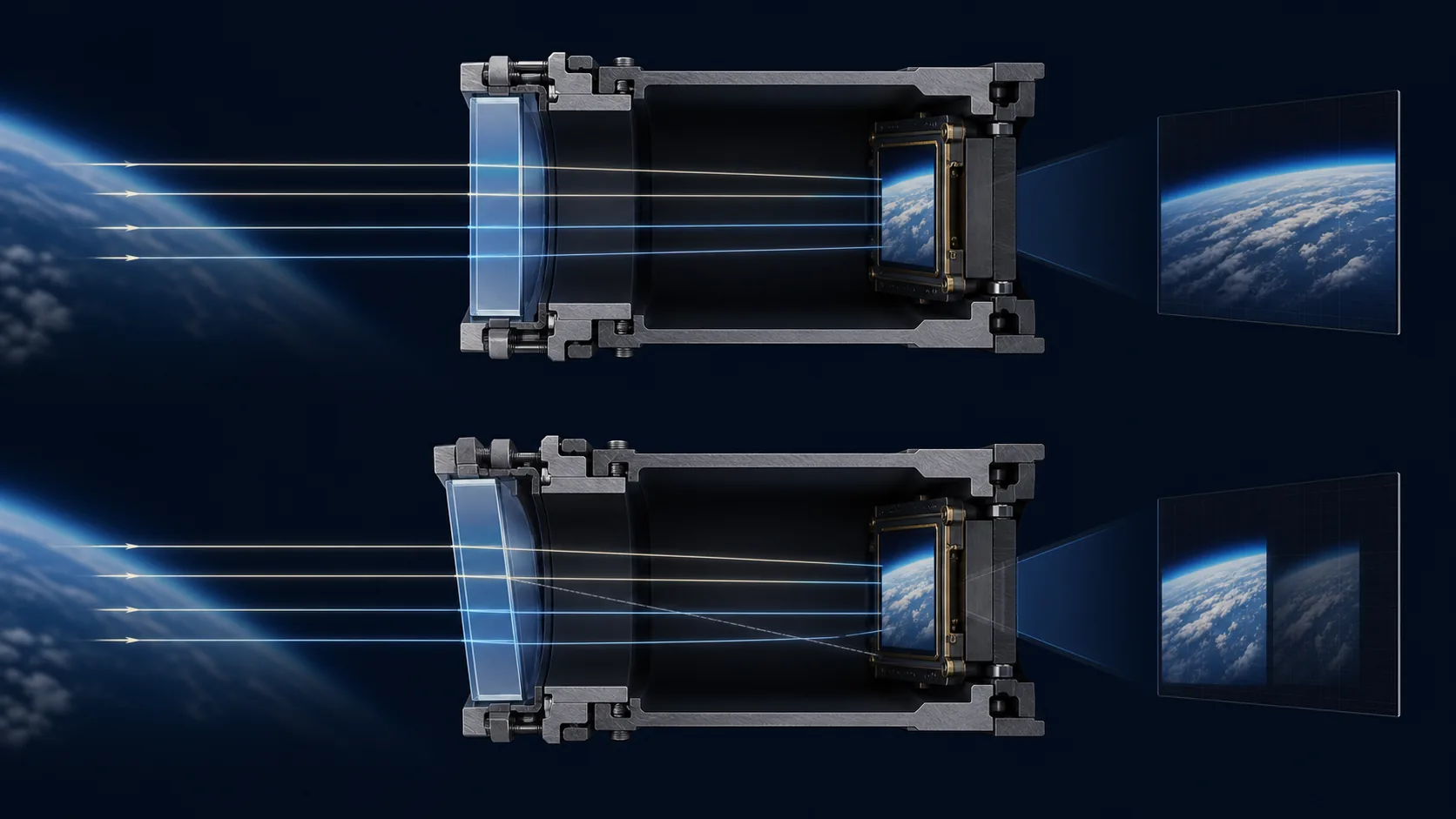
How flat must an aerospace camera window be?
Flatness should be derived from allowable transmitted wavefront error, focus shift, line-of-sight change, or image-quality loss. A window near a pupil, close to the detector, or used with a fast lens can have different sensitivity. Total surface flatness is not always the best metric because the two surfaces can partially cancel or combine in transmission.
Define clear aperture, support condition, test wavelength, fringe interpretation, power removal, and whether transmitted wavefront or individual surface figure controls acceptance. For a protective non-imaging sensor, a relaxed profile may be adequate. For metrology or long-range imaging, tighter control may be justified. Thin windows can sag during measurement or distort when mounted. Use a support method representative of the specification and evaluate the installed condition where needed. Tightening flatness without controlling wedge, homogeneity, coating stress, and frame deformation can fail to improve the image. Allocate an optical error budget before setting the drawing.
Environmental and structural control: pressure, sealing, heating and contamination
An external optical window must preserve the detector path while the housing, seal, heater and frame respond to altitude, temperature, moisture and surface exposure. Component screening identifies risks; acceptance of the configured instrument confirms that the optical signal remains usable.
| Environmental factor | Component or assembly risk | Component evidence | Complete-system acceptance |
|---|---|---|---|
| Pressure differential and altitude | Deflection, seal load and transmitted-wavefront change | Thickness, edge, support and structural analysis | Imaging, ranging or detection under the specified pressure condition |
| Temperature and heating | Local deformation, coating stress, hot spots and boresight movement | CTE compatibility, heater pattern and thermal analysis | Line-of-sight and image or signal checks in the powered thermal state |
| Condensation | Scatter, obscuration and signal loss | Dew-point, sealing, purge, desiccant and heater inspection | Cold-start, humidity and optical-recovery testing |
| Rain erosion and particles | Pitting, haze, coating loss and forward scatter | Representative surface and coating screening | System performance after the defined exposure |
| Cleaning and fluids | Coating, edge ink, adhesive and seal degradation | Actual chemical, tool, pressure and cycle testing | Optical, leakage and retention checks after cleaning |
Condensation control may use sealing, dry-gas purge, desiccant, a membrane vent, heating or thermal design that keeps the inner surface above the local dew point. Surface treatments can change droplet behavior but do not remove water vapor. Record the installed configuration, power-off state, warm-up time, pressure, humidity, surface temperature and recovery criteria so a clear window is demonstrated as a system result rather than a material claim.
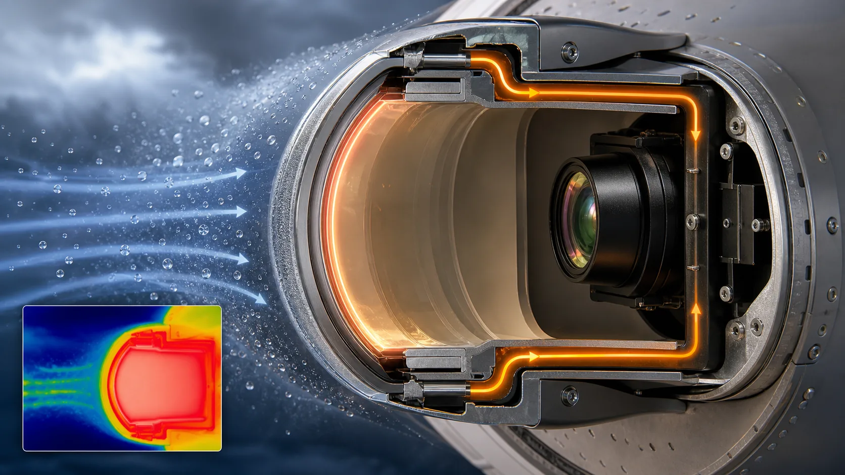
Ground-based airport weather-sensor windows
A ground-based airport weather-sensor window is specified from its measurement task: visible imaging, near-infrared ranging, precipitation, cloud height, visibility or another defined band. Identify wavelength, field of view, aperture, incidence angle, transmission, reflection, haze, wedge and allowable image or ranging error, then add rain, dust, insects, ultraviolet exposure, ice, cleaning, heating and internal-condensation conditions.
These instruments are not airborne equipment. RTCA DO-160, SAE AS8034C and FAA AC 25-11B do not apply automatically; the instrument manufacturer, airport project, governing measurement requirement and approved configuration determine the acceptance method. Evaluate signal level, focus or range error, ghosts, heater operation and condensation after the window is mounted.
Locate every coating, mask, seal land, heated zone and replaceable optical area on the drawing. The terminology boundary between an optical window and an RF radome is stated in the note below.
Official and standards references for this guide
Source status was reviewed on August 12, 2026. The contract, certification basis, approved equipment configuration and controlled document revision determine actual applicability. Obtain authorized copies of paid standards.
- FAA, AC 25-11B - Electronic Flight Displays, for applicable Part 25 display-system guidance; it does not independently qualify a cover glass.
- DLA ASSIST, MIL-STD-3009 - Lighting, Aircraft, Night Vision Imaging System (NVIS) Compatible, active and dated April 4, 2024.
- SAE International, AS8034C - Minimum Performance Standard for Airborne Multipurpose Electronic Displays, for installed electronic displays within its stated scope; head-up displays and independent cover-glass qualification are outside that scope.
- RTCA, DO-160 and FAA AC 21-16G for applicable airborne-equipment environmental qualification methods.
- ISO, ISO 10110-1:2019 and ISO 10110-5:2026 for optical-drawing and surface-form notation when adopted by the project; these drawing standards are not aviation product qualification.
Contact Us
Your feedback fuels our growth, and your questions drive our solutions.
We value your feedback, inquiries, and suggestions. Please feel free to get in touch with us
General inquiries
Please contact us via sales@bo-glass.com, and we will reply to you as soon as possible.
Interested to work with us
Drop your resume at info@bo-glass.com
and we will get back to you shortly.
We uses the contact information you provide to us to contact you about our relevent content, products, and services.