
Airfield Ground, Elevated & Special Lighting Glass
Glass components for runway, taxiway, elevated, obstruction, heliport, and other airfield lighting systems.
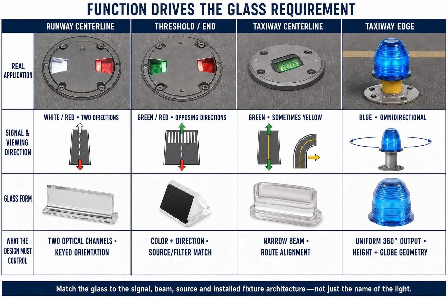
Airfield application comparison
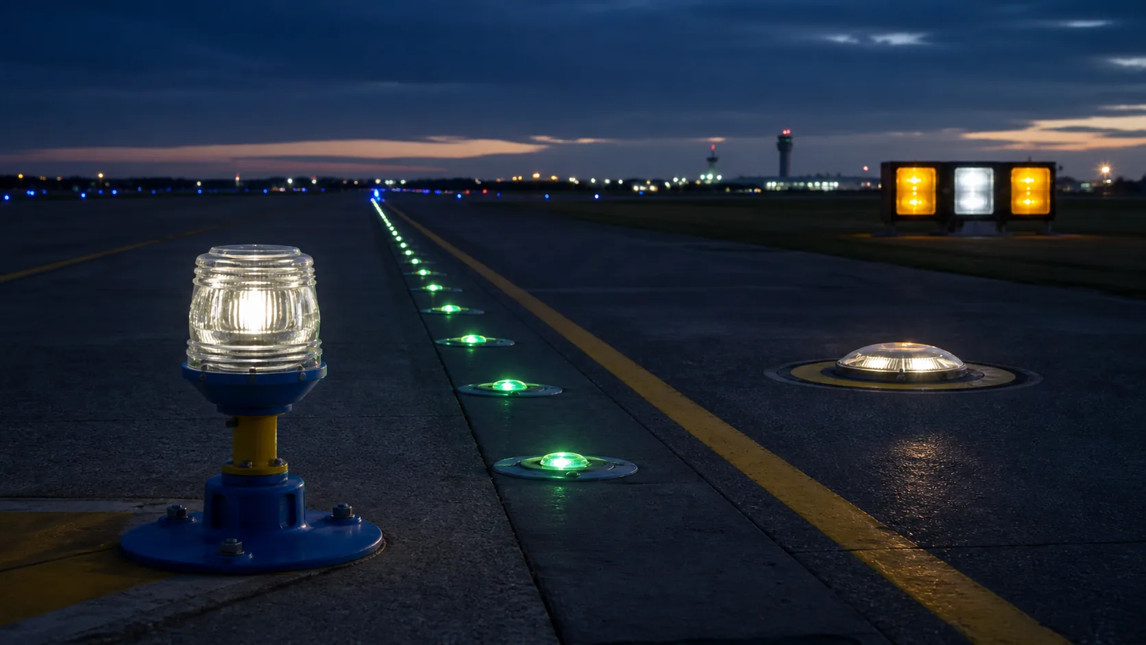
This guide covers elevated runway and taxiway lights, obstruction lights, heliport and vertiport lights, and illuminated signs. In-pavement prisms, PAPI optics, detailed color and LED matching, and maintenance diagnosis are covered in separate focused guides. The overview references them only where needed to define the system boundary or route a project to the correct technical page.
| Application | Typical glass | Primary technical basis | Key procurement inputs | Verification level |
|---|---|---|---|---|
| Elevated runway or taxiway light | Globe, ring lens or filter | FAA AC 150/5345-46F | L-type, color, source and direction | Complete fixture |
| Obstruction light | Red cover, clear window or prismatic globe | FAA AC 150/5345-43J | Equipment type, flash behavior, source and coverage angle | Complete fixture |
| Heliport light | Low-profile lens or green optic | AC 150/5345-46F and AC 150/5390-2D | Approach angle, installation style and protrusion | Fixture and facility design |
| Vertiport light | Low-profile directional or omnidirectional optic | AC 150/5345-46F and FAA EB 105A | Reference aircraft, operating conditions and viewing envelope | Project-defined configuration |
| Runway or taxiway sign | Protective panel or diffuser | FAA AC 150/5345-44L | Sign type, size, luminance and color | Complete sign equipment |
Airfield Ground Lighting Systems and Glass Components
The same piece of glass can have a different job depending on where the light sits and what information it gives a pilot. A runway edge light, stop-bar light, threshold light, and taxiway centerline light differ in viewing direction, color, intensity, load, and maintenance exposure. Understanding the system context makes it much easier to translate an airport-lighting requirement into the correct prism, lens, cover, filter, or diffuser.
Airfield applications and optical functions
Airfield ground lighting provides visual guidance for approach, landing, takeoff, taxi, holding and movement-area identification. The optic may distribute a directional or omnidirectional beam, create a defined signal color, mix discrete LED emitters, protect the source, seal the housing or diffuse a sign face. Its specification therefore starts with the operational signal and complete fixture—not with glass color and diameter alone.
For elevated runway and taxiway lights, identify the FAA L-type or other equipment classification, intended direction and color, light source, optical center, angular intensity target, mounting datum and environmental class. A green taxiway optic and a green threshold optic may use the same color name but require different beam geometry, orientation and validation. Provide the equipment manufacturer and model for replacement work because two fixtures meeting the same performance specification can use non-interchangeable glass.
In-pavement lights use load-bearing prisms and sealing interfaces that require a separate geometry, load-path and replacement discussion; see the In-Pavement Runway & Taxiway Light Prisms guide. PAPI uses a tightly controlled source-filter-lens-housing relationship and red/white transition; see the PAPI Lenses, Filters & Optical Components guide. This page retains only the system context needed to distinguish those applications from elevated and special airfield lighting.
Color, source and fixture configuration
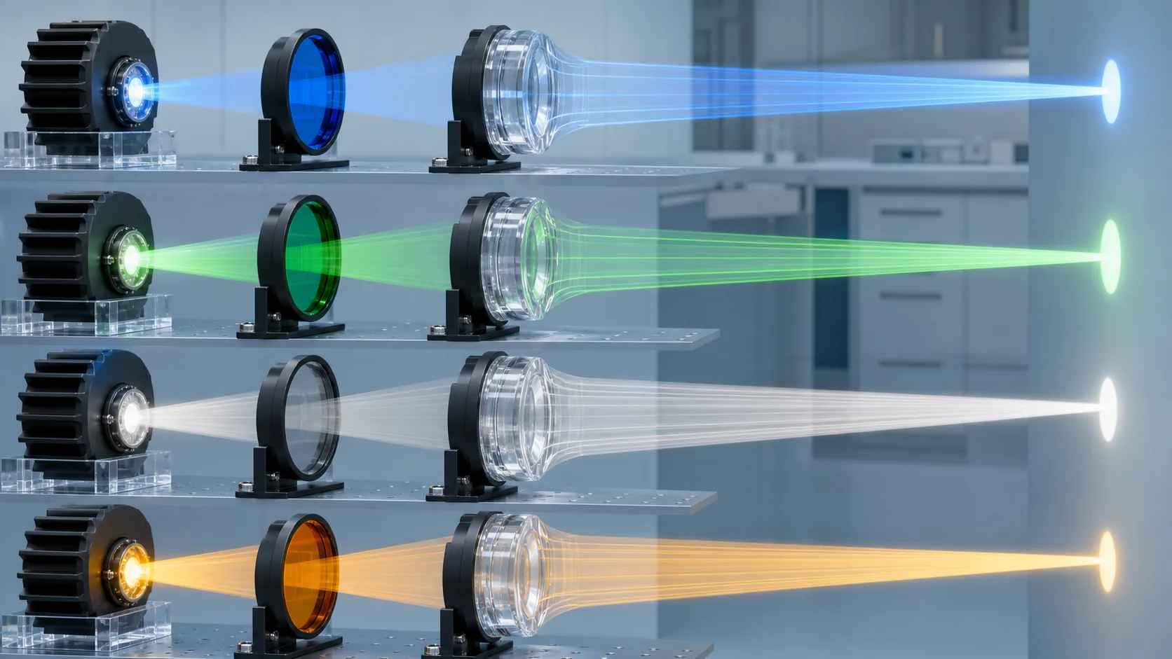
White, red, green, yellow and blue signals communicate different operational information, so color is a controlled performance characteristic rather than a cosmetic choice. The observed result belongs to the full optical chain: lamp or LED spectrum, electrical operating point, glass transmission, thickness, incidence angle, temperature, aging, coating and other optics. A request for “aviation green glass” is incomplete unless the controlling color boundary, source and measurement conditions are identified.
When converting from incandescent to LED, re-evaluate color and beam performance instead of reusing a legacy filter by appearance. Discrete LED emitters can also create bright sectors or source images through a clear globe. Development samples should be evaluated in the intended fixture over relevant operating settings and beam positions. Production controls may then use correlated spectral, colorimetric, thickness, material and source-bin evidence.
FAA L-type designations help identify equipment families, directions, colors and complete-fixture requirements, but they are not component drawings and do not establish interchangeability between manufacturers. For deeper treatment of chromaticity, spectrum, photometry and LED matching, use the Aviation Optical Design, Color & LED Matching guide. For contamination, cleaning, haze and field optical loss, use the Environmental Reliability, Failure & Maintenance guide.
Elevated Airfield Light Glass Components
Elevated lights avoid aircraft wheel loads, but their exposed position creates a different design problem. Wind-driven rain, ice, ultraviolet exposure, thermal cycling, cleaning, and accidental impact all act on the globe or lens, while its shape and color still have to preserve the intended signal. This chapter connects those service conditions with practical choices in glass geometry, coloration, sealing, and replacement control.
Elevated-light glass and uniform output
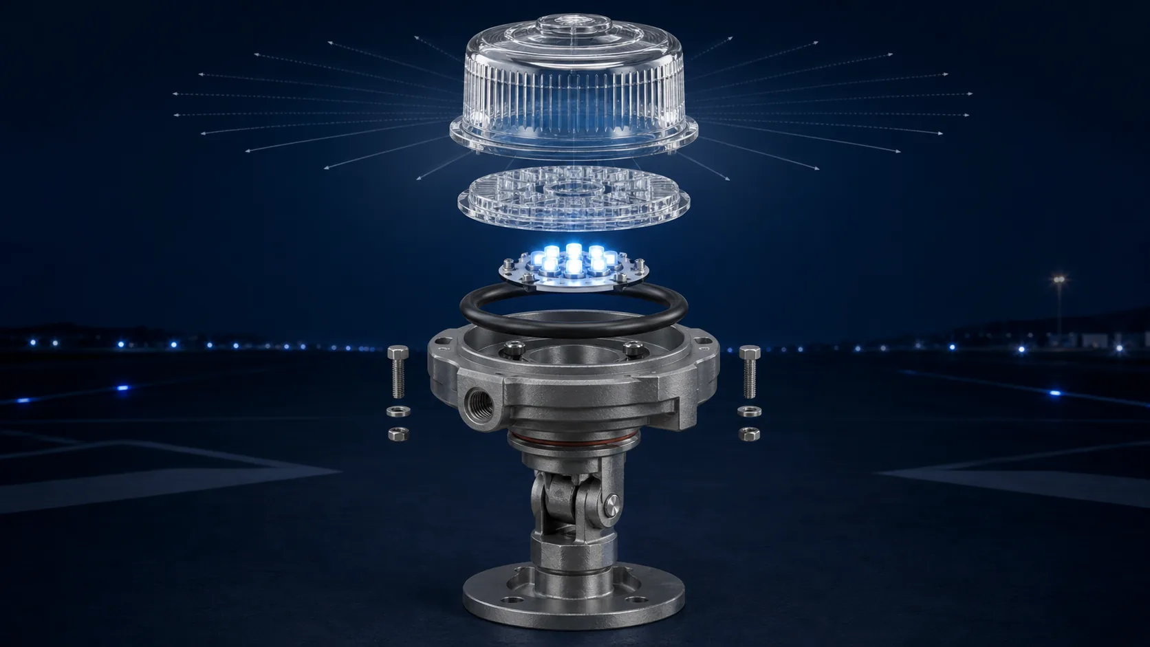
Elevated airfield lights can use clear or colored domes, cylindrical covers, prismatic rings, Fresnel-type lenses, internal filters, protective windows, and diffusers. Some components mainly protect the source; others form a directional or omnidirectional distribution. A single molded cover may combine color, beam control, weather protection, and mechanical interface features.
The application determines the geometry. Runway edge and threshold/end lights need recognizable sectors and colors. Taxiway edge lights commonly require blue output around the fixture. Runway guard or stop-bar applications may be directional and flashing. Approach lights can require high intensity and controlled direction. The glass must work with the selected lamp or LED, reflector, and housing to deliver the complete-unit photometry. For development, provide the equipment classification, source model, optical center, mounting orientation, required color, angular distribution, and environmental conditions. For replacement, provide the approved part number and drawing revision; visually similar globes are not necessarily optically interchangeable. The supplier can distinguish optical mold surfaces from cosmetic zones and protect the gasket interface and exposed edges during finishing and shipment.
- Uniform output depends on rotational geometry, wall thickness, refractive features, surface condition, source centering, and the interaction with the housing. A molded ring lens may use repeating prisms to redirect light into the required vertical band. A simpler colored globe may rely on source and reflector geometry while preserving consistent transmission around its circumference.
- Mold seams, eccentricity, color streaks, local thickness changes, bubbles, and logos can create weak or bright sectors. The lower rim can also block light if it sits too deeply in the housing. LED arrays introduce discrete emitters that may become visible through clear glass, so diffusion or optical mixing may be required without excessive loss.
- Control the profile relative to the mounting datum, not just overall diameter. Inspect roundness, wall thickness, rim flatness, and optical features. Rotate development samples in the actual fixture during photometry to find sector variation. A visual spin check can detect major defects, but quantitative fixture measurements establish whether uniformity is adequate. If orientation matters, add a key rather than assuming the globe is rotationally interchangeable.
Weather, frangibility, corrosion and sealing
The environmental problem. An elevated globe or lens must retain color and photometry while its seal and mounting experience wind, rain, snow, ice, UV, contamination, and thermal movement. Water pockets over an optical zone and rigid rim contact are often more dangerous than exposure to uniform cold or heat.
Useful scale from the current FAA fixture standard. AC 150/5345-46F defines an operating environment of −40 to 131 °F (−40 to 55 °C). Its wind requirements are 300 mph (483 km/h) for L-804, L-861, and L-862 fixtures and 150 mph (241 km/h) for other elevated fixtures. These are complete-fixture conditions; they are not claims that an unsupported glass globe can carry the same load.
Design response. Shed water away from the useful aperture, avoid ice traps, maintain gasket compression through differential movement, and evaluate heater-created gradients. After assembled exposure, cracks, looseness, leakage, coating change, color shift, and photometric loss reveal whether the glass-and-mounting system remained functional.
Frangibility is the controlled breakaway behavior of a support or installation so an aircraft impact is not made more hazardous by a rigid obstacle.
It does not mean the glass is intentionally weak or that random shattering is acceptable. In elevated airfield lights, the frangible feature is usually in the support, coupling, or mounting system, while the optical cover must remain durable during normal operation and maintenance.
Confusing the terms can create poor designs. Making a globe thinner does not demonstrate fixture frangibility and can increase field failures from handling, hail, vibration, or thermal shock. Conversely, very strong glass does not compensate for a noncompliant support structure. Each requirement has its own load path and verification.
The fixture manufacturer should perform the specified frangibility test on the appropriate configured unit. The glass drawing should address its own interface, retention, fragment behavior where relevant, and environmental durability. After breakaway testing, evaluate whether fragments or retained parts create secondary concerns. Procurement language should clearly say “glass cover for a fixture using a frangible support,” not “frangible glass,” unless a specific controlled glass-breakage requirement actually exists.
- The glass body may be chemically durable, but the assembly includes coatings, screen printing, seals, adhesives, retainers, and metal hardware that can degrade in salt-laden moisture. Salt deposits also scatter light and attract water. Corrosion products can expand at the rim, stain the optic, reduce seal compression, or make maintenance difficult. A coating can lose adhesion even when the substrate remains sound.
- Evaluate the complete interface. Avoid galvanic and crevice-corrosion traps, provide drainage, select compatible gasket and retaining materials, and keep coating edges away from uncontrolled seal contact where possible. The cleaning method must remove salt without scratching the optical surface or attacking a coating.
- Qualification uses the applicable fixture salt-fog procedure, but development tests on coated glass and interface coupons can identify risks earlier. Inspect after exposure for haze, iridescence, color change, corrosion staining, seal damage, and transmission loss. A pass/fail photograph is not enough when the component influences light output. For coastal projects, maintenance intervals and rinse procedures should be part of lifecycle planning rather than an afterthought.
Common causes include gasket relaxation, incorrect compression, a warped or chipped glass rim, thermal-expansion mismatch, vibration, loose retainers, contaminated seal surfaces, assembly error, and housing distortion.
An uneven molded rim can create alternating high-pressure and low-pressure regions. Excessive torque may crack the glass or extrude the gasket; insufficient torque allows movement and water entry.
Define rim flatness, thickness, edge finish, and sealing-zone defects according to the housing design. Use positive retention that remains effective across temperature and vibration while avoiding point loads. Assembly instructions should specify gasket orientation, cleanliness, lubricant if permitted, tightening sequence, and torque. If the globe can be rotated, ensure that rotation does not damage the seal or change optical orientation.
Leak testing should follow environmental and mechanical exposures, not only initial assembly. When a field unit leaks, inspect the glass, gasket, retainer, and housing together. Replacing the gasket without correcting a warped rim or corroded seat may provide only temporary improvement. Record lot and assembly data so recurring problems can be traced to geometry, material, or process.
Glare control and replacement checks
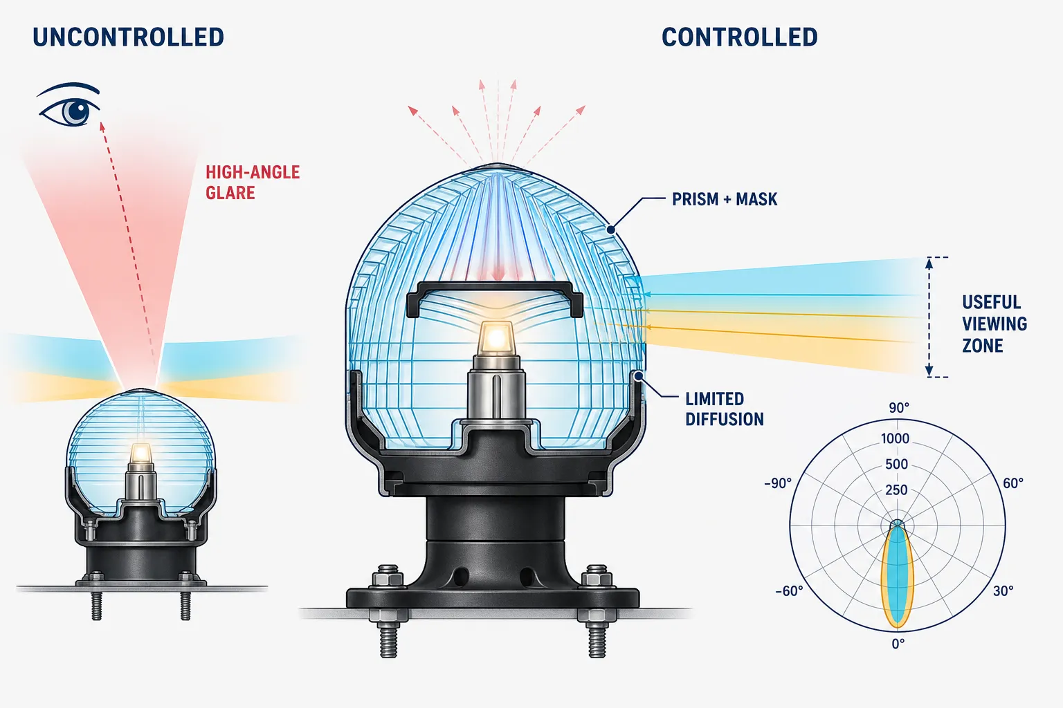
- Glare is reduced by placing useful intensity in the required viewing zone and limiting stray light outside it. Prismatic features, masks, diffusing zones, source shielding, and surface treatments can help. However, broad diffusion often reduces peak intensity and can spread light into unwanted angles. The goal is controlled distribution, not simply a softer-looking globe.
- Start with the operational photometric requirement and pilot viewing geometry. Model the source, glass, housing, and surrounding structures. Pay attention to mold rounding and surface finish because ideal sharp-prism models can overpredict control. Colored glass also affects perceived brightness and must meet the required color boundary.
- Verify on a goniophotometer and inspect for high-angle peaks, bright seams, chip images, and sector variation. If frosting is used, define haze or texture in measurable terms and confirm durability after cleaning. A visually comfortable sample viewed at arm’s length is not representative of a high-intensity signal observed from an aircraft. Fixture-level data and field evaluation are the appropriate decision tools.
Confirm the fixture manufacturer, model, equipment type, part number, color/direction configuration, drawing revision, source technology, mounting interface, and approved replacement status.
Replacement inspection checklist:
- Compare height, rim diameter, gasket land, keying, optical profile, and color—not only appearance. Check whether the original qualification depends on a specific supplier, mold, material, or coating.
- Inspect the housing and retainer before installing the new glass. Corrosion, burrs, old gasket material, or deformation can damage the replacement and cause leakage.
- Use the specified new gasket and tightening procedure. Verify orientation marks and clean the optical surfaces with an approved method.
- After replacement, perform the maintenance checks required by the fixture manual: operation, color, alignment, sealing, and photometric or field checks as applicable. If a third-party part is proposed, the design or approval owner must determine interchangeability.
- A part that physically fits can still alter beam distribution or color enough to invalidate the configured performance.
A replacement is acceptable only when fit, optical output, color, sealing, and approval status remain compatible; visual similarity alone is not enough.
Obstruction, Heliport, Vertiport and Special Airfield Glass
These applications are grouped together because they create viewing and environmental conditions that conventional runway lights do not always encounter. Signals may need to remain recognizable from steep approach angles, through rotor or propeller wash, around buildings, or in compact installations with limited thermal space. Their glass components are best selected by starting with the signal function and operating environment, then working back to color, diffusion, impact resistance, and mounting.
What glass requirements are typical for obstruction lights?
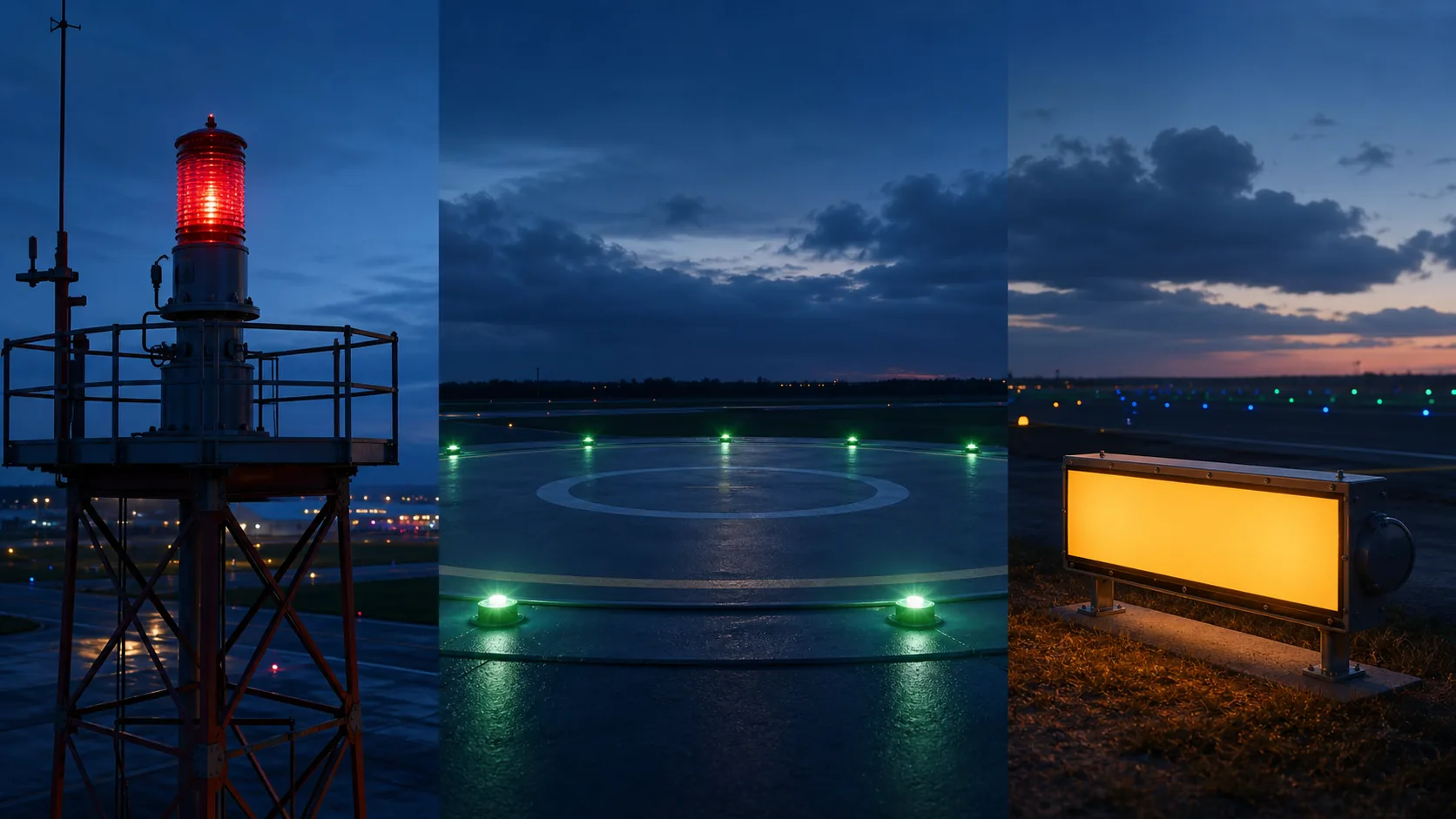
Obstruction lights must remain conspicuous in their required color, intensity, flash behavior, and coverage while exposed to weather, solar radiation, temperature, wind, humidity, salt, and maintenance. Glass components can include red covers, clear high-intensity windows, prismatic globes, internal filters, and protective lenses. FAA AC 150/5345-43J is the active U.S. equipment specification for obstruction lighting.
The glass design must account for source technology. A discharge source, incandescent lamp, and LED array have different spectra, heat, and emitting geometry. The cover must not create weak azimuth sectors, color shift, or excessive reflection back into the source chamber. UV-stable bulk color can be valuable, but coating or direct-LED approaches may be appropriate with verified performance. Because the complete equipment is qualified, flow component controls from fixture tests. Confirm spectral transmission, color, geometry, sealing interface, coating durability, and exposed-surface quality. For tower service, consider long maintenance intervals and difficult access: a slightly more durable, easily cleaned surface can be worth more than a marginal initial transmission gain.
Heliport and vertiport lighting environments
Heliport and vertiport lights support touchdown and lift-off areas, final approach and takeoff areas, flight-path alignment and perimeter identification. Their viewing geometry can include steep approaches and close-range observation, while fixtures may face rotor wash, debris, weather, low-protrusion constraints and limited maintenance access. The optic may need omnidirectional green output, a controlled vertical distribution, secure retention, sealing, impact resistance and stable color with the intended LED source.
Use the documents at the correct level. FAA AC 150/5345-46F provides equipment requirements for applicable light fixtures. FAA AC 150/5390-2D addresses heliport planning, design and construction. FAA Engineering Brief 105A supplements that heliport guidance for the defined vertiport scope. EB 105A should not be presented as universal approval for every eVTOL aircraft, operating concept or site; projects outside its stated reference-aircraft and operating assumptions require project-specific coordination and requirements.
Rotor wash can drive grit, water and debris across the optical surface at high speed. It can also create rapidly changing pressure and contamination patterns. Shield vulnerable glass edges, avoid debris pockets, preserve the useful optical aperture when wet and verify coatings against abrasion, cleaning fluids and ultraviolet exposure. A taxiway optic should not be adapted unchanged without confirming the approach envelope, glare, protrusion, installation style and complete-fixture performance.
Procurement inputs should identify the facility type, governing documents, reference aircraft where applicable, operating conditions, viewing envelope, fixture classification, source, mounting style and maintenance constraints. Environmental and mechanical qualification belongs to the defined complete fixture or facility configuration; a generic glass impact value cannot establish compliance.
How is glass used in illuminated runway and taxiway signs?
- Glass can be used as a protective front, internal diffuser, printed panel, or optical element in illuminated guidance signs. Its functions are to protect the light source and legend, distribute luminance evenly, maintain color contrast, and withstand weather and cleaning. Many sign systems use polymers for mass and impact reasons, so glass should be selected where its heat, scratch, chemical, or long-term optical stability provides a clear benefit.
- The panel must not create bright source images, dark zones, double reflections, or glare that reduces legend recognition. Printed or colored layers require stable chromaticity and adhesion. Thermal expansion, wind load, frame support, and fragment behavior should be addressed. A large flat panel needs edge protection and uniform support because local frame distortion can create tensile stress.
- FAA AC 150/5345-44L defines U.S. runway and taxiway sign equipment requirements. The sign OEM should derive component transmission, diffusion, color, durability, and dimensional controls from the complete sign design. Replacement panels must preserve legend, luminance, color, and approved configuration—not merely fit the frame.
Official and standards references for this guide
Source status was reviewed on August 12, 2026. The contract, certification basis, approved equipment configuration and controlled document revision determine actual applicability. Obtain authorized copies of paid standards.
- FAA, AC 150/5345-46F for applicable runway, taxiway, heliport and vertiport light fixtures.
- FAA, AC 150/5345-43J for obstruction lighting equipment.
- FAA, AC 150/5345-44L for runway and taxiway signs.
- FAA, AC 150/5390-2D - Heliport Design for heliport planning, design and construction.
- FAA, Engineering Brief 105A - Vertiport Design, supplemental guidance with a defined reference-aircraft and operating scope.
Contact Us
Your feedback fuels our growth, and your questions drive our solutions.
We value your feedback, inquiries, and suggestions. Please feel free to get in touch with us
General inquiries
Please contact us via sales@bo-glass.com, and we will reply to you as soon as possible.
Interested to work with us
Drop your resume at info@bo-glass.com
and we will get back to you shortly.
We uses the contact information you provide to us to contact you about our relevent content, products, and services.