
Glass Coating Guide
Glass coatings can modify optical transmission, infrared control, electrical conductivity, surface energy and durability. A successful specification connects the required function to the operating environment, an appropriate deposition process and measurable acceptance criteria.
What Is a Glass Coating?
A glass coating is a functional layer applied to one or more glass surfaces. Depending on the material and process, its thickness may range from a molecular-scale surface treatment to a multilayer optical stack. The coating may change how the glass transmits or reflects light, emits infrared energy, conducts electricity, repels liquids or resists wear. Performance depends on the complete system: substrate composition, surface preparation, coating materials, layer thicknesses, deposition conditions and any post-treatment.
BO-GLASS Coating Capability and Supply Scope
The matrix below reflects information published on the BO-GLASS website, its coating capability page and its materials overview. It separates confirmed company-level capabilities from items that remain project-specific.
| Delivery model | Publicly supported scope | Project boundary | Documentation position |
|---|---|---|---|
| In-house manufacturing | BO-GLASS publicly identifies in-house expertise in precision glass molding, fused pressing and borosilicate forming, supported by glass cutting, finishing and other post-processing services. | The website does not identify every coating technology or coating line as exclusively in-house. The production route is confirmed during quotation. | Sample approval and final quality inspection form part of the published workflow. Project records are defined in the control plan. |
| Managed through specialist partners | The coating page states that BO-GLASS coordinates its core facility with a network of local specialists and manages communication, quality control and logistics. | The RFQ requests confirmation of the production route, coating process, usable chamber envelope and any subcontracted operation relevant to control of the part. | Availability of spectral data, adhesion results and environmental-test reports is established in the quotation and agreed test plan rather than assumed. |
| Engineering guidance only | Material selection, coating selection, design-for-manufacture review, sampling and feedback support are available before production approval. | Guidance does not establish production capability or compliance until drawings, samples, acceptance criteria and the manufacturing route have been approved. | Recommendations are design inputs. A production certificate or test report is issued only when contractually included. |
| Capability item | Published or confirmed position |
|---|---|
| Glass types | The website lists soda-lime, float, low-iron, borosilicate and borosilicate 3.3, aluminosilicate, tinted, anti-glare, laminated, patterned, wired and quartz glass. Coating compatibility is reviewed for the selected grade and surface condition. |
| Size and curvature | No universal coating-specific minimum, maximum or curvature envelope is published. Feasibility is established from the drawing, substrate condition, fixture concept and selected coating route. |
| Inspection | The published workflow includes sample confirmation and final quality checks. Dimensional, visual, optical, electrical or environmental inspection is selected according to the product control plan. |
| Full test reports | A full spectrum, adhesion or environmental report is not assumed for every order. The RFQ records the method, edition, sampling, raw-data format, acceptance criteria and whether an accredited external laboratory is required. |
What Functions Can Glass Coatings Provide?
Anti-Reflective and Optical Filter Coatings
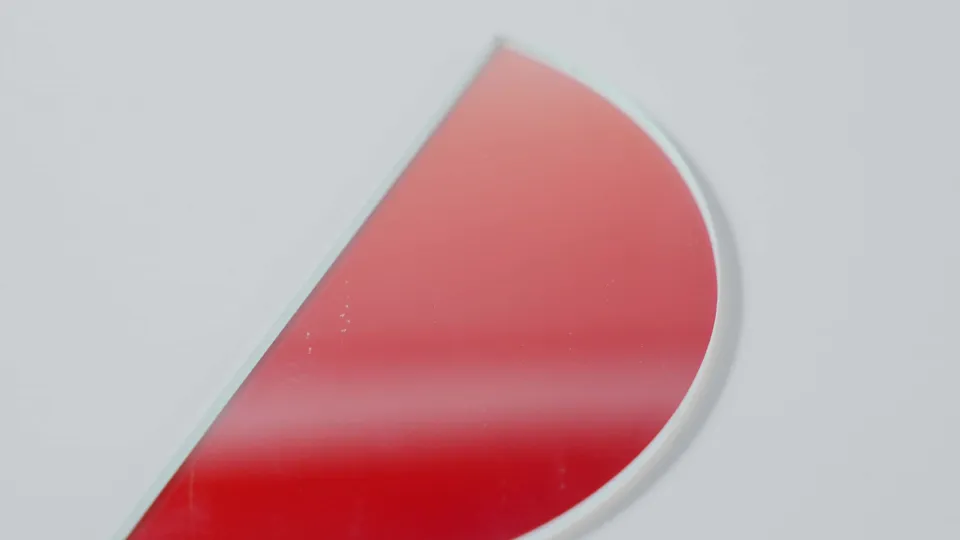
Anti-reflective coatings reduce reflection over a specified wavelength band, while filter coatings transmit, block or reflect selected spectral regions. A valid requirement states the wavelength range, angle of incidence, polarization, illuminated area and whether the value applies to one surface, one finished element or the complete optical path. Film design and thickness uniformity are matched to the substrate geometry and the measurement method.
Low-E and Infrared-Control Coatings
Low-emissivity and solar-control coatings manage infrared radiation while maintaining the required visible appearance. Building glazing, vehicle roofs and heated windows use different coating stacks because their spectral targets, substrate shapes, tempering sequences and environmental loads differ. Requirements are expressed through applicable values such as emissivity, visible transmittance, solar transmittance or reflectance, together with the glass build-up and test standard.
Conductive and EMI-Shielding Coatings
Transparent conductive oxides, thin metal stacks and conductive meshes can support heating, sensing or electromagnetic shielding. Optical transmission and sheet resistance are specified together because improving one may reduce the other. In many automotive touch displays, the conductive electrodes are below the cover glass or inside a laminated sensor stack. Wear of the external anti-fingerprint layer affects cleanability and friction but does not normally expose the buried electrode. Designs with a top-surface conductor require separate review.
Glove operation is a system-level capacitive-sensing issue. It depends on cover thickness and dielectric constant, electrode geometry, controller sensitivity, signal-processing settings, and glove material and thickness. Verification therefore takes place on the assembled display rather than from conductive-film resistance alone.
Hydrophobic, Oleophobic and Protective Coatings
Hydrophobic and oleophobic treatments reduce surface energy, making water and oils easier to remove. Hard oxide, nitride or hybrid layers can add abrasion or chemical resistance. A single initial contact-angle value does not represent durability. Acceptance covers the initial condition, cleaning chemistry, wiping material, load, cycle count and the permitted change in contact angle, haze, appearance or friction after exposure.
Three Questions Before Selecting a Coating
What function must the coating provide?
Start with the system requirement, then translate it into measurable coating criteria. Optical values need a wavelength band, incidence angle, polarization and aperture. Electrical values need sheet resistance, busbar layout and allowable non-uniformity. Surface requirements need a defined liquid, contact-angle method and durability sequence. Avoid specifying the highest available number unless a system calculation shows that the additional performance changes the product outcome.
What environment will the product face?
The environment definition records whether the coated surface is indoor or outdoor, exposed or laminated, and subject to UV, temperature cycling, humidity, salt, disinfectants, solvents, abrasion or repeated handling. Medical applications are validated with the actual disinfectant concentration, dwell time, rinse procedure and sterilization cycle. Generic claims such as a fixed number of autoclave cycles are not transferable between deposition methods, film thicknesses, interlayers, substrates or sterilization conditions.
ISO 13485:2016 is a quality-management-system standard for medical-device organizations. It does not certify that a coating has passed sterilization, chemical-resistance or durability testing. Those performance claims rely on product-specific protocols and evidence.
Which specifications justify the additional cost?
Performance is evaluated at system level. More coating layers, tighter tolerances and larger inspection areas can increase deposition time, monitoring effort and rejection risk. The practical trade-off is the least complex specification that meets the functional requirement with adequate reliability margin. The quotation separates mandatory values from target values and identifies the test method, sampling plan, cosmetic zone and consequences of any permitted edge exclusion.
Glass Coating Process Comparison
| Process | Main strengths | Primary constraints | Typical applications |
|---|---|---|---|
| Magnetron sputtering | Dense films, scalable area, good process control | Line-of-sight coverage, vacuum tooling, geometry-dependent uniformity | Low-E, conductive and optical multilayers |
| Vacuum evaporation | High-purity optical films and flexible material selection | Source-distribution and line-of-sight limits | Optical filters and precision components |
| Sol-gel coating | Accessible wet process and flexible part size | Cure requirements and thickness-uniformity control | Protective, anti-reflective and functional oxide layers |
| PECVD | Reactive films at moderated substrate temperature | Plasma uniformity, chamber and chemistry constraints | Silicon-based barriers and selected protective films |
| ALD | Highly conformal and precise thickness control | Low deposition rate and comparatively high cost | High-value precision parts and barrier layers |
Magnetron Sputtering
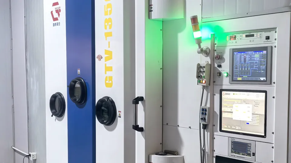
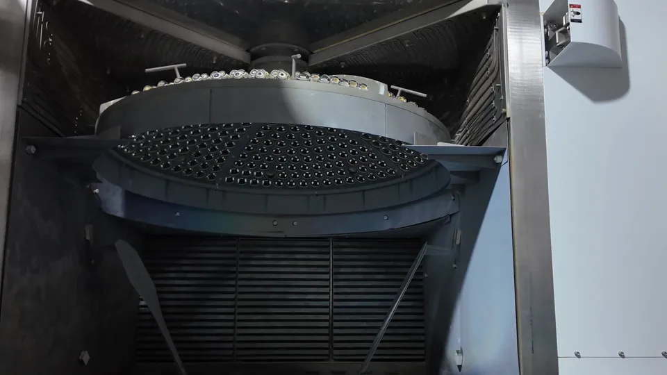
Magnetron sputtering ejects material from a target in a vacuum plasma and deposits it on the substrate. It is widely used for dense metal, oxide and nitride films and can be scaled to large flat glass. Coverage remains geometry-dependent because the arriving flux is directional. Curved surfaces, recesses and fixture shadows require rotation, masks or project-specific uniformity studies.
Vacuum Evaporation
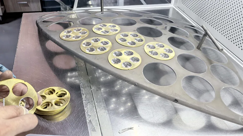
Vacuum evaporation heats a source material until it reaches the substrate as vapour. Electron-beam and thermal sources are common in optical coating. The process supports many optical materials, but thickness distribution depends on source position, substrate distance and planetary motion. Adhesion and film density depend on material, substrate preparation, temperature and any ion assistance, not on the process name alone.
Sol-Gel Coating
Sol-gel methods form an inorganic or hybrid network from a liquid precursor applied by dipping, spinning or spraying. They can accommodate large or irregular parts without a vacuum chamber. Uniformity, edge build-up, solvent control and curing are central design issues. Substrate selection accounts for the drying or heat-treatment sequence, while production validation covers bath ageing and environmental control.
PECVD
Plasma-enhanced chemical vapour deposition uses plasma-activated precursors to form films such as silicon-based dielectrics and selected carbon-containing layers. It can provide better step coverage than directional physical-vapour processes, but uniformity still depends on electrode design, plasma distribution and part loading. Review of each coating stack covers gas chemistry, residual stress, substrate temperature and chamber capability.
ALD
Atomic layer deposition builds a film through sequential self-limiting surface reactions. It provides excellent thickness control and conformal coverage on complex surfaces, but cycle time and equipment cost can limit its use on large, low-value glass. ALD is normally selected when conformality, barrier performance or nanometre-scale control justifies the slower process. Available chamber size and precursor compatibility are confirmed with the selected supplier.
Design Factors That Affect Coating Yield
Yield review takes place before the coating stack and mechanical drawing are released. The following design factors often narrow the production window.
| Design factor | Typical yield risk | Design response |
|---|---|---|
| Complex geometry and shadowing | Non-uniform thickness on steep slopes, recesses and fixture contact areas | Provide non-optical clamping zones and confirm coating-flux access |
| Large, thin or warped substrates | Handling damage, thermal bow and mask or roller contact | Set flatness limits, support strategy and thermal budget |
| Overly tight optical tolerances | Normal process variation becomes rejection | Link limits to system sensitivity and define the measurement aperture |
| Excessive layer count and stress | Accumulated thickness error, particles, cracking and spectral drift | Use the simplest stack that meets required functions |
| Coating-substrate incompatibility | Delayed delamination after humidity or thermal cycling | Validate cleaning, surface activation and transition layers |
Coating Testing and Acceptance Criteria
Optical Performance
Transmission and reflection values are incomplete unless their boundary conditions are stated. Define whether the requirement applies per coated surface, per finished optical element including substrate absorption, or to the complete optical system. Also state the wavelength or band, angle of incidence, polarization, aperture, temperature where relevant, and the measurement instrument or standard.
Across a 15-element optical path, increasing per-element transmittance from 99.0% to 99.5% raises theoretical system transmittance from 0.9915 ≈ 86.0% to 0.99515 ≈ 92.8%. This provides about 8% more transmitted signal under otherwise identical conditions; it does not double the photon count.
This simplified multiplication assumes that 99.0% or 99.5% is the measured transmittance of each complete optical element. If the value applies per surface, a 15-element system with two relevant surfaces per element requires a 30-surface calculation. The example does not separately model scattering, stray-light paths, multiple reflections between elements or detector-response differences.
For laser optics, thermal loading is governed primarily by absorptance rather than total transmission loss. Reflected power leaves the optical path, while absorbed power contributes directly to coating and substrate heating. With incident power P, the approximate absorbed heat is P × A, where absorptance A is measured or otherwise justified. A 1,000 W beam and 99% transmission do not by themselves establish a 10 W thermal load.
What Does a 5B Tape-Test Rating Actually Indicate?
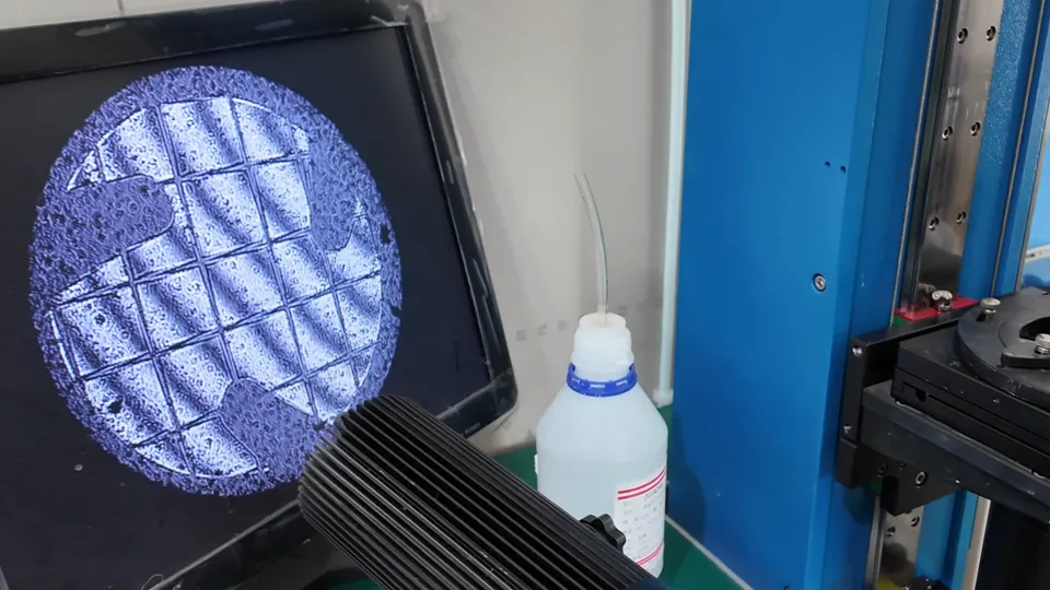
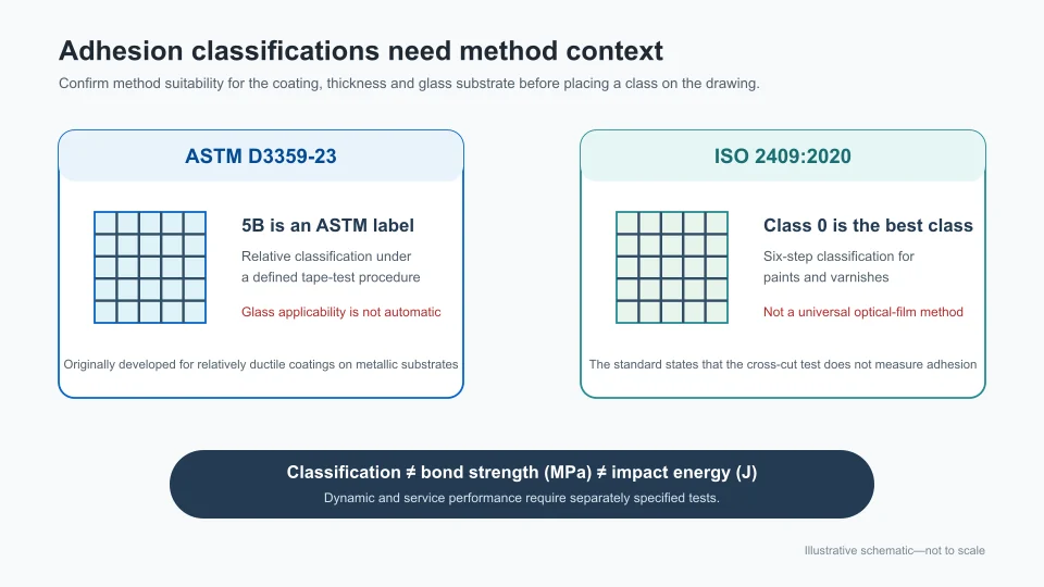
5B is a classification used by ASTM D3359-23. ISO 2409 uses a six-step classification in which Class 0 is the best result. The methods are similar empirical cut-and-separation assessments, but their labels are not interchangeable or technically equivalent. ASTM D3359 also states that the method does not distinguish higher adhesion levels and does not provide an absolute bond-rupture force. ISO 2409:2020 states that its cross-cut test is not a means of measuring adhesion.
ASTM D3359 was developed for relatively ductile coatings on metallic substrates, while ISO 2409 addresses paints and varnishes. Neither method is automatically suitable for every glass substrate, brittle optical film or nanometre-scale coating. A customer request for 5B therefore triggers a method-suitability review covering the coating type, film thickness, glass surface, cutting procedure and failure mode before the rating is placed on the drawing.
Neither result can be converted into MPa, impact energy or a universal service-life value. Final performance is demonstrated with the specified drop-ball, impact, sand and dust, thermal-cycle or complete-assembly test. A complete report states the standard and edition, method, coating thickness, substrate, cut spacing, tape, conditioning, operator procedure, failure location and acceptance class.
Abrasion and Cleaning Durability
Abrasion results depend on the test apparatus, abrasive material, load, stroke length, cycle count, cleaning fluid and endpoint. A statement such as resistant to 10,000 wipes has little value without those conditions. Define the permitted change in haze, transmittance, color, contact angle, electrical performance and appearance after the sequence. For touch products, test the complete cover, sensor and controller assembly when the failure mode involves user interaction.
Salt Spray and Environmental Aging
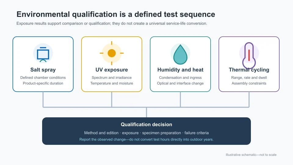
A 1,000-hour salt-spray result is treated as a qualification or comparative result under a defined test method, not as a direct prediction of outdoor service life. ASTM B117-26 defines the salt-spray apparatus, procedure and chamber conditions; it does not prescribe the product specimen, exposure period or interpretation. ASTM also states that stand-alone salt-spray results have seldom correlated with natural-environment performance and that extrapolation is not always predictable. No generic conversion to months or years is used.
| Test report item | Required detail |
|---|---|
| Method | Standard, edition and any deviations |
| Exposure | Solution type, concentration, pH, temperature and duration |
| Specimen preparation | Scribed or unscribed, edge sealing, orientation and conditioning |
| Failure criteria | Corrosion, blistering, discoloration, delamination and adhesion limits |
| Supplementary ageing | Cyclic corrosion, UV, humidity-heat and thermal cycling as required by service conditions |
Common Coating Failures
Failure analysis begins with the observed change and the layer in which it occurs. The matrix below links common symptoms to confirmation methods and practical corrective directions.
| Failure mode | Possible causes | Confirmation method | Improvement direction |
|---|---|---|---|
| Pinholes and particle contamination | Incomplete cleaning, airborne particles, fixture debris, chamber contamination, outgassing or non-uniform film nucleation | Dark-field inspection, defect mapping, optical microscopy and, when justified, cross-section or surface analysis | Improve cleaning, handling, fixture maintenance, chamber conditioning and particle controls; review nucleation and pre-treatment |
| Haze increase | Particle growth, surface roughness, porous film structure, chemical residue, moisture uptake or interfacial reaction | Pre/post haze and transmission measurement, scatter mapping, microscopy and surface-roughness comparison | Control surface preparation, deposition chemistry, film density, cure conditions and environmental sealing |
| Cracking or crazing | Residual stress, excessive film thickness, thermal-expansion mismatch, thermal shock or substrate flexure | Microscopy before and after thermal or mechanical exposure, crack-pattern analysis and substrate-curvature comparison | Rebalance layer stress, reduce thickness, add a compatible transition layer and revise the thermal or handling sequence |
| Electrical resistance drift | Oxidation, microcracking, non-uniform thickness, contact degradation, moisture ingress or busbar damage | Sheet-resistance mapping, continuity and contact-resistance checks, microscopy and controlled environmental ageing | Improve encapsulation, barrier design, contact metallurgy, thickness uniformity and strain isolation |
| Chemical staining or corrosion | Incompatible cleaner, exposed reactive layer, insufficient barrier density, edge ingress or galvanic interaction | Exposure with the actual chemical and dwell time, followed by visual, optical, electrical and microscopic comparison | Change the cleaning specification, strengthen the barrier or edge seal, and remove incompatible material combinations |
| Edge failure after cutting or lamination | Coating in the cut or bond zone, cutting damage, adhesive incompatibility, trapped contamination or lamination stress | Edge and cross-section inspection, failure-location analysis and testing after the actual cutting and lamination sequence | Add edge deletion or keep-out zones, change the process sequence, improve edge preparation and validate the interlayer |
Delamination
Delamination may result from contamination, inadequate surface activation, weak chemical bonding, excessive residual stress, thermal-expansion mismatch or environmental attack. Failure analysis records where separation occurred: within the coating, between coating layers, at the coating-substrate interface or within the substrate. Microscopy, surface analysis and comparison with process records are more reliable than assigning every failure to cleaning or adhesion alone.
Scratching and Packaging Damage
Packaging changes can create a new abrasion mechanism even when the coating process is unchanged. Stacked parts may move under vibration, and trapped particles can produce scratches or local pressure marks. Packaging validation defines separator material, cleanliness, orientation, stack height, load, transport profile and inspection zones. Surface damage is evaluated separately from failure of a buried sensor or conductive layer.
Color or Spectral Shift
Color or spectral shift can be caused by thickness non-uniformity, process drift, angle-dependent interference, material oxidation or changes introduced by tempering and lamination. The acceptance plan defines the measured area, reference illuminant, observer angle, wavelength resolution and allowed lot-to-lot variation. For curved or large glass, a measurement map is usually more informative than a single centre-point value.
Information Required for a Coated-Glass RFQ
| RFQ category | Information to provide |
|---|---|
| Substrate | Glass type, composition if known, dimensions, thickness, flatness, edgework and strengthening state |
| Coated surface | Side designation, coated area, masks, keep-out zones and clamping allowance |
| Optical requirements | Transmission, reflection, haze, color or spectrum with wavelength, angle, polarization and aperture |
| Electrical requirements | Sheet resistance, uniformity, busbars, heating power or shielding target |
| Environment | Temperature, humidity, UV, chemicals, sterilization, abrasion and cleaning sequence |
| Acceptance | Test standards and editions, limits, cosmetic zones, sampling plan and reporting format |
| Production | Prototype and annual volume, packaging, traceability, change control and delivery schedule |
| Supply responsibility | Confirm in-house coating, approved external coating partner or selection support only |
Application-Specific BO-GLASS Resources
Automotive and Electronic Display Glass
BO-GLASS publishes product information for vehicle headlight glass lenses and covers and an industry page for electronics and appliance instrument glass. These pages support discussions about molded or tempered lighting glass, control panels, display covers and related fabrication. They do not by themselves establish qualification for every automotive coating stack. An automotive RFQ still records the complete cover, sensor or lighting construction, applicable OEM test plan, environmental sequence and supply responsibility.
Medical and Laboratory Glass
The healthcare and laboratory glass page describes custom medical components, optical parts and laboratory glassware from prototype through production. For coated parts, the project definition includes the glass grade, coated surface, biological or chemical exposure, cleaning agent, sterilization method and required inspection evidence. The application page describes manufacturing scope; it does not replace coating-specific sterilization, chemical-resistance or regulatory validation.
Aerospace and Airfield Lighting Glass
The aerospace and airfield lighting page covers runway and taxiway optics, signal lenses, glass domes, instrument covers and sensor windows. Coating requirements remain tied to the actual assembly and program specification. Optical bands, viewing angles, colorimetry, thermal cycling, impact, fuel or de-icing-fluid exposure and documentation are agreed at RFQ stage. Publication on the industry page is not a blanket airworthiness or program approval for an unspecified coating.
Standards Referenced
Contact Us
Your feedback fuels our growth, and your questions drive our solutions.
We value your feedback, inquiries, and suggestions. Please feel free to get in touch with us
General inquiries
Please contact us via sales@bo-glass.com, and we will reply to you as soon as possible.
Interested to work with us
Drop your resume at info@bo-glass.com
and we will get back to you shortly.
We uses the contact information you provide to us to contact you about our relevent content, products, and services.