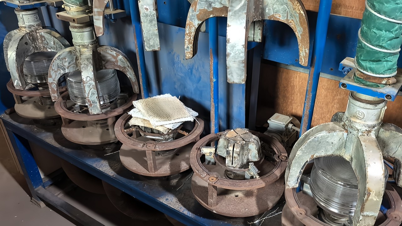
Vertical tempered glass production line

Vertical tempered glass production line is a kind of equipment that transports glass vertically and improves the strength and durability of glass through heating and rapid cooling processes.

Vertical tempered glass production line

Physical tempering equipment is specialized machinery used to strengthen glass by heating it to a high temperature and then rapidly cooling it using air or other cooling mediums. It ensures the glass meets stringent safety standards for automotive, architectural, and industrial applications.The vertical tempered glass production process is shown in the figure
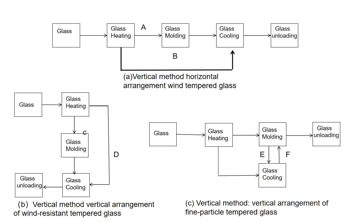
A—curved tempered glass; B—flat tempered glass; C—curved tempered glass;
D—flat tempered glass; E—curved tempered glass; F—flat tempered glass

The glass is lifted vertically along the upper edge and then heated, formed, quenched, and other processes are carried out to produce tempered glass. This production line has two layouts. Special load-bearing molds can be used instead of clamps when producing small pieces of glass. All production lines can be controlled by an integrated control system, which mainly includes the operating computer and the software required for inputting and controlling process parameters.


(1) Vertical method horizontal arrangement of tempered glass production line production equipment includes heating furnace, molding machine, and wind grille. These equipment are arranged on the same horizontal floor, and their layout is shown in Figure (a) and Figure 1. This production line can produce flat tempered glass and curved tempered glass.
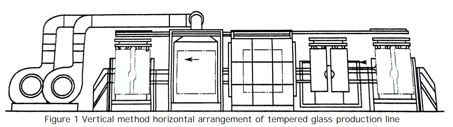
(2) Heating furnace vertical method The heating furnace of the tempered glass production line is arranged horizontally. There are two types of heating furnaces: electric heating furnaces and gas heating furnaces. The glass is hung by a glass-hanging trolley from one end of the heating furnace and sent out from the other end. It is a slit-type furnace with doors on both sides and the top. The slit is as small as possible, generally not more than 40mm.
① Electric heating furnace The electric heating furnace consists of a furnace body, heating elements, furnace door, broken glass groove, roller, and control equipment (see Figure 3-10 for the inner structure). To meet the production and use requirements, according to the output, it can be a heating chamber or several heating chambers connected, and the number of heating chambers can be up to 5. The innermost layer of the furnace body is a furnace wall made of clay refractory bricks. The side of the refractory bricks close to the furnace is tooth-shaped. The electric heating element is placed in the tooth-shaped groove of the refractory bricks. The width of the furnace is 500-650mm. The middle layer is aluminum silicate fiber felt or high-temperature resistant mineral wool felt, the outer layer is a steel plate shell, and the steel plate is outside the steel column. There are two types of furnace bodies: fixed and movable. The fixed furnace body has a steel column as its outer steel frame. The lower part of the column is buried in the ground. The furnace body cannot be opened or moved. Half of the movable furnace body is installed on a trolley. When the heating furnace is inspected, it is pulled apart by a traction machine. The maximum pulling distance is 600mm for maintenance operations. The other side is the same as the fixed furnace body. The specific width of the furnace is 650mm for the fixed type and 500mm for the movable type.
Heating elements use nickel-chromium wire or iron-chromium wire. The nickel-chromium heating wire is wound into a spiral tube with a wire diameter of 2.5~3mm and a spiral tube diameter of 24mm. The pitch is determined by the design according to the area of ​​the heating element required for each heating zone. There are 24 heating zones, and the two ends of the heating wire in each zone are connected to the power wiring board. The furnace doors on both sides and the top door are sliding furnace doors, which are driven by cylinders or oil cylinders to open and close in parallel.
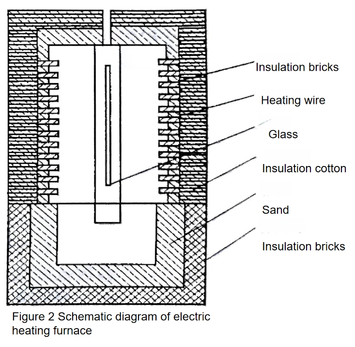
The number of users of movable heating furnaces is gradually decreasing due to the troublesome operation of removing and resetting the movable furnace body, the difficulty of sealing the furnace body, and the high heat loss. At present, most vertical-tempered electric heating furnaces use fixed furnace bodies. When using a fixed furnace body, a pit is set at the bottom of the furnace, and a set of fixed rollers can be set in the pit, on which a steel plate trough for broken glass is placed. During production, the broken glass fragments fall into the trough. There is a covered pit under the ground outside the furnace door, which is connected to the pit of the furnace. However, the pit passage under the furnace door is usually blocked with insulation bricks, and the outside is sealed with asbestos mud. When repairing the heating furnace, the insulation bricks can be removed, and the steel plate trough for broken glass can be pulled out, and people can enter the furnace for repair. At present, most of them use electronic computer programs to control the temperature of the heating furnace, the opening and closing of the furnace door, and the transportation of the glass-hanging trolley. The technical parameters of the heating furnace are shown in the following table.

Technical Parameters of the Heating Furnace

Item Parameter Item Parameter
Maximum Glass Size (mm × mm) 2200 × 1800 Working Temperature (℃) 650 - 680
Glass Thickness (mm) 3 - 12 Heating Zone Division 24 zones
Rated Heating Power (kW) 250 Power Supply Voltage (V) 380 / 220
② Gas-fired heating furnace The combustible gases used in gas-fired heating furnaces are mostly natural gas and butane. The furnace body consists of a furnace wall, insulation layer, steel shell, and steel columns. The furnace wall is built with clay refractory bricks, among which the nozzle bricks are arranged according to the design. The furnace width is 900mm. The furnace wall is the innermost layer of the furnace body. The insulation layer in the middle is aluminum silicate fiber felt or refractory high-temperature mineral wool felt; the outer layer is a steel plate shell, and the outer steel column is used as the skeleton. The exhaust seam width of the furnace top is 30mm.
Flameless nozzles are used. There is a separate valve on the pipeline of each nozzle to adjust the gas supply. Natural gas and air are pre-mixed and connected to each nozzle by pipeline. The main pipe is equipped with a total gas pressure regulating valve. According to the furnace temperature requirements, after the pressure of each flameless nozzle is adjusted, the total regulating valve automatically adjusts the gas supply pressure of the entire route to ensure the stability of the total pressure, thereby stabilizing the furnace temperature.
The furnace body is only equipped with side doors, and there is no door on the top of the furnace. The combustion exhaust gas overflows from the top of the furnace and is discharged to the outside through the exhaust hood and exhaust pipe. The furnace door is a horizontal sliding type and is driven by a cylinder to open and close. The technical parameter range of the gas-fired heating furnace is shown in the following table.
Technical Parameters of Gas Heating Furnace

Technical Parameters of Gas Heating Furnace

Item Technical Performance Item Technical Performance
Glass Processing Size (mm × mm) (1800 × 1050) ~ (1800 × 3000) Working Temperature (℃) 650 - 680
Glass Thickness (mm) 3 - 12 Butane Main Pipe Pressure (kPa) 7.80
Nozzle Pressure (kPa) 1.5 - 2.0
Combustible gas is another heat source for tempered glass production. Compared with electric heating, it is relatively cheap. Combustible gas can meet the process requirements of heating glass to the required temperature for quenching stably, evenly, and quickly. However, it will inevitably produce noise and exhaust gas during combustion, which will affect the environment. This type of heating furnace has 1 to 6 chambers, with a partition wall between the two chambers. The number of chambers is determined according to the designed production capacity.
(3) Moulding machine The Moulding machine is one of the equipments for bending tempered glass. Its characteristics are that the female mold and the male mold are pressed against each other, and the mold surface is made of soft material or pasted with soft material with low thermal conductivity to prevent the glass surface from being scratched and reduce the heat transfer of the glass to the mold, which causes the glass temperature to drop too quickly.
The molding machine is composed of a mold, extrusion device, rail, adjustment device, base, hydraulic system, and control system.
The molds are of two types: solid mold and hollow mold. Solid molds are used in one-step tempering process, and hollow molds can be used in one-step and two-step tempering processes (the one-step process is that the tempered wind grille and the bending mold are connected by docking, and the bending and quenching of the glass are completed at the same station. The two-step process is that a bending device consisting of a front and a rear mold is set between the tempering heating furnace and the tempering wind. When the glass is heated to a temperature close to the softening temperature in the heating furnace, it is quickly moved into the bending device, bent into the required curved surface by the bending device, and then quenched to obtain a curved tempered glass product). When the solid mold is used in the one-step process, the cooling equipment (plate hole wind grille) and the molding press are together, as shown in Figure 3.
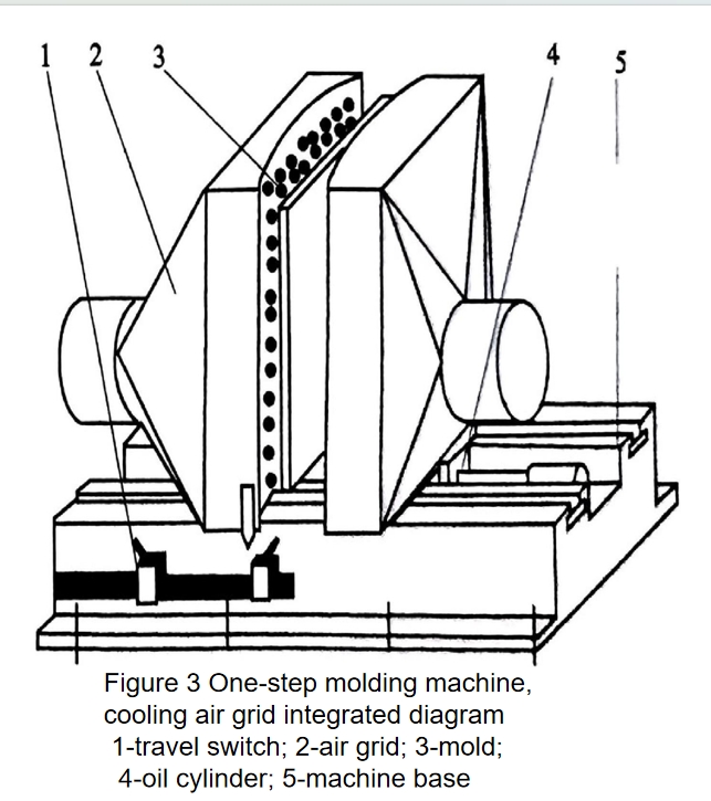
The molding machine device is installed on the frame track in the one-step method and the two-step method. The hydraulic drive device automatically controls the glass molding device to move before and after the glass is formed and controls the glass molding time. In the one-step method, the wind grille and the molding machine are combined into one, which reduces the transportation time after the glass is formed and can improve the tempering degree of the glass. The molding time is generally controlled between 1.5 and 2s, and the molding distance can be automatically adjusted according to the shape of the glass.
The structural forms of the mold include box type, tube type, plate type, etc.
The box-type mold is welded with steel plates into a box with convex and concave curved surfaces. The shape and curvature of the curved surface match the shape and curvature of the finished tempered glass. The curvature of the mold surface needs to consider the compensation amount of rebound during the transportation and quenching process after the glass is bent. Its surface is covered with several layers of soft materials such as glass cloth or ultra-fine cotton paper. When used as a molding wind grille, the box body is connected to the cooling air duct with a hose, and the mold surface is drilled with blowing holes.
The tubular mold is welded into a frame with steel pipes, and the male mold is made completely according to the shape and curvature of the finished tempered glass. The molding mainly relies on the bent steel pipes around the male mold to press the hot glass onto the female mold. This mold can be used in a one-step or two-step tempered glass production line. The wind grille can be used on the same molding machine as the mold, but the wind grille must be used with a wind nozzle or air outlet.
The male mold of the plate mold is bent from an aluminum plate.
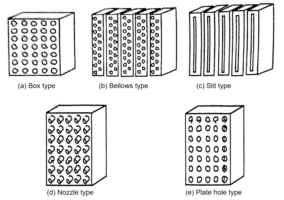
(4) Wind grille cooling wind grilles are divided into box type and wind box type according to the box body; they are divided into nozzle jet type, slit type, plate hole type wind grilles, etc. according to the nozzle form (Figure 3-12). Wind grilles are also divided into fixed type or adjustable type according to the installation form. After the glass is heated to near the softening temperature, it is sent to the wind grille, and the box-shaped, strip-shaped, or tube-shaped wind grilles with nozzles on both sides perform circular motions relatively upward and downward evenly or regularly. Many small nozzles are arranged in the wind grille corresponding to the nozzles on the opposite side, and the cooling air blows from these small nozzles to the glass for quenching or cooling.
① Box-type wind screen [Figure (a)] consists of bellows, nozzles, circular motion or swing mechanism, transmission system, frame, etc. The bellows is a box made of welded steel plates, connected to the cooling air duct with a hose. A pair of bellows stand opposite each other on the frame or hanger, and many nozzles or small holes are arranged on the opposite bellows’ surface. The adjustable nozzle needs to be welded with a short tube on the two-step bellows or the one-step mold, and the rubber nozzle is inserted into this short tube. The nozzle length is generally 83-103mm, the distance between the nozzles on the two opposite bellows is 90-120mm, and the hole diameter is 4-5mm. The arrangement of the nozzles is rectangular or plum blossom-shaped. The former has a spacing of 40mm×40mm or 30mm×30mm, and the latter has a spacing of 44mm×26mm or 25mm×12.5mm. The nozzles of the one-step plate hole windscreen are drilled directly on the bellows, and the hole position corresponds to the opposite bellows. Generally, one type of glass is equipped with a set of one-step plate-hole wind grilles, and an adjustable wind grille can be used for multiple varieties.
② The wind box type wind grille [Figure (b)] is based on the box type wind grille, which divides the two integral wind boxes into several small wind boxes, and the small wind boxes are connected from the main confluence pipe. Each small wind box is arranged and adjusted according to the shape of the product, and flat or curved tempered glass products can be produced. The wind box type wind grille also has two types: nozzle type and plate hole type.
③ Slit type wind grille [Figure (c)] is composed of a slit type wind duct. Generally only flat tempered glass is used.
④ The nozzle-type wind grille [Figure (d)] is composed of a steel tube with a nozzle, which is combined according to the shape of the glass product and arranged corresponding to the shape of the product to produce flat or curved tempered glass.
⑤ Plate hole type wind grille [Figure (e)] is welded from steel plates. Many small holes are drilled on the grid surface with a certain curvature. Several layers of soft materials such as asbestos paper or glass cloth are pasted around the holes to prevent the glass surface from being scratched and reduce the heat of the glass from being transferred to the die, which causes the glass temperature to drop too quickly. The box is installed on the track of the molding machine and connected to the bellows with a hose. When producing fully tempered glass, the blowing holes are arranged regularly. When arranged in a rectangular shape, the spacing between the blowing holes is 25mm×25mm or 30mm×30mm, and the hole diameter is 4~5mm. Plate hole type wind grille is used in the one-step process, and generally does not make circular motion or reciprocating swing. Some manufacturers also use one-step wind grille with circular motion or reciprocating swing.
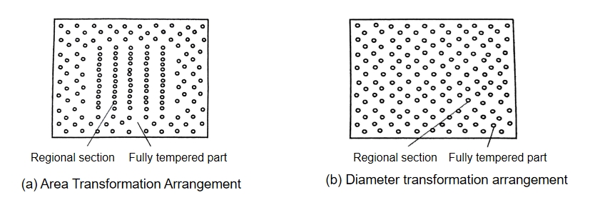
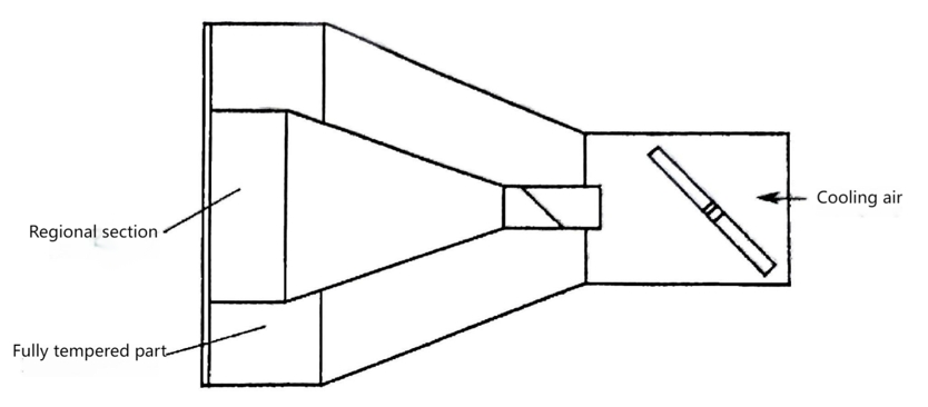
⑥ Regional tempered wind grille The Regional tempered wind grille is divided into three forms. The first is to change the arrangement of the nozzles in the main viewing area [Figure 3-13 (a)]. The ratio of the distance between the nozzles in the main viewing area and the nozzles in the peripheral area is generally 1:2. The second is to change the nozzle aperture of the main viewing area [Figure 3-13 (b)]. The ratio of the nozzle aperture of the main viewing area and the nozzle aperture of the peripheral area is generally 1: (1.5 ~ 2.5). In the above two cases, when the nozzles are arranged in a plum blossom shape, the distance is 44mm × 26mm, and the apertures of the main viewing area and the peripheral area are φ3mm and φ5mm respectively. In actual production, to make the stress distribution on the glass surface gradually change, a transition zone is set between the two areas, and the nozzle aperture is φ4mm. The third is to supply air in different areas inside the wind grille, control the air pressure separately, and set valves on their respective pipelines to control the different cooling air pressures of the main viewing area and the peripheral area, which can ensure the fragmentation requirements of the two areas.

Figure 3-13 Regional Tempered Wind Grille Layout
Contact Us

Your feedback fuels our growth, and your questions drive our solutions.

We value your feedback, inquiries, and suggestions. Please feel free to get in touch with us

General inquiries

Please contact us via sales@bo-glass.com, and we will reply to you as soon as possible.

Interested to work with us

Drop your resume at info@bo-glass.com
and we will get back to you shortly.

    We uses the contact information you provide to us to contact you about our relevent content, products, and services.