
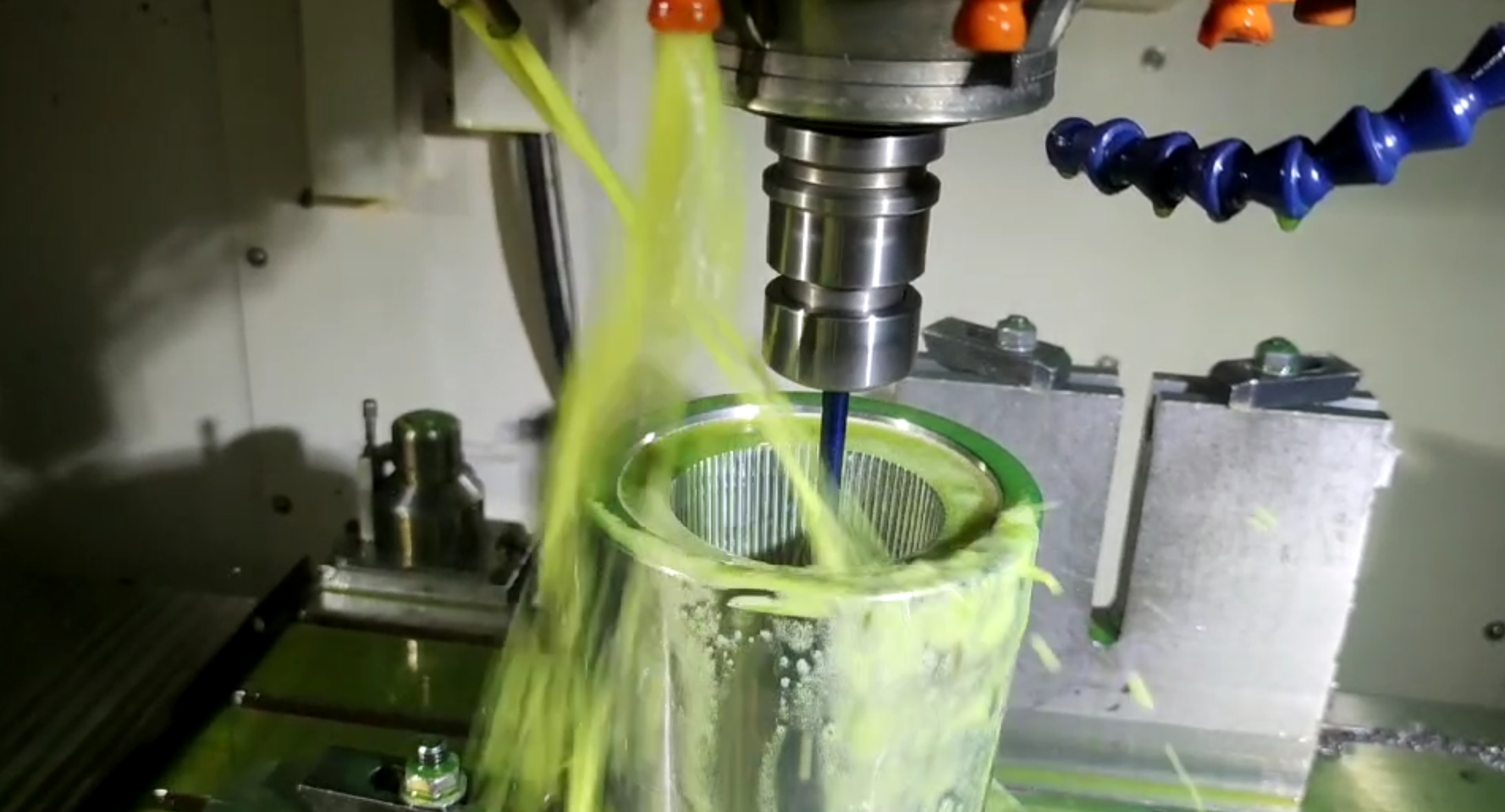
Mould Making
- 20% off first order
- Samples in as little as 3 weeks
- CE RoHS & REACH ISO 4802 EN 12150
All uploads are secure and confidential
Multiple Glass Manufacturing
Capabilities – All Under One Roof
20 years of expertise in all areas of
irregular custom shaped glass!
Nearly 200 types in 5 categories
Over 200 different production technologies
Over 4000 customer service experiences ensure efficient and effective communication, fast and precise fulfillment of specific requirements for custom
20+
Company Establishment
200+
Production Technology
4000+
client


Trustworthy expert in glass manufacturing solutions


The first stage of quality control begins with a comprehensive design review. Our team provides detailed DFM feedback, helping to optimize your design for moldability and reducing potential production issues.
During production, we implement robust in-process quality control measures. From inspecting incoming raw materials to final product checks, our skilled operators and technicians monitor and refine every step to maintain consistency and accuracy. We use advanced inspection tools like CMM, XRF analyzers, and micrometers to ensure precision.
To guarantee the final product’s quality, we conduct First Article Inspections (FAI), dimensional checks, and functional testing. Each part undergoes a thorough final inspection by expert technicians trained to spot even the smallest discrepancies.
With our ISO 9001:2015 certification and commitment to excellence, we ensure that every part leaving our facility upholds the highest standards of quality and reliability.
Blowing mold
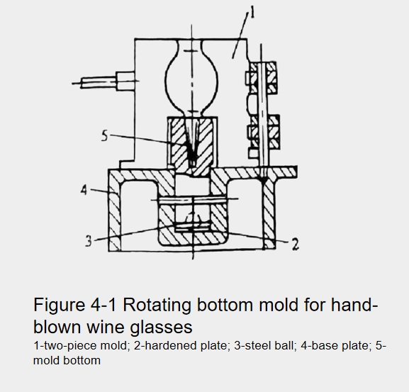
Figure 4-1 shows a more complex bottom-turning mold for artificially blown wine glasses. The two-piece mold 1 is mounted on the pin and tightly fits the seat plate 4. The mold bottom 5 is mounted on the steel ball 3 and the hardened plate 2.
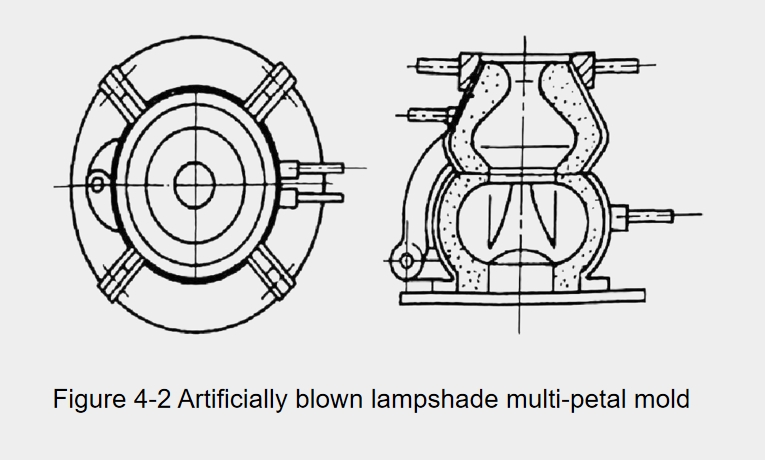
Artificial blow molds can also have several parting surfaces. Figure 4-2 shows a mold for blowing lampshades, the lower part of which consists of 2 parts and the upper part consists of 4 parts. As long as the combination of the molds is appropriately changed, products of various shapes can be blown.
Why———
Choose Us

Pressing die
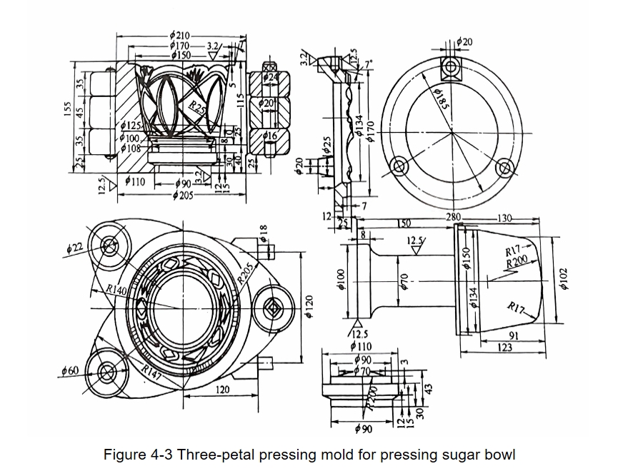
For products with odd-numbered pattern distribution, a three-petal mold with an angle of 120° is often used. For products with even-numbered pattern distribution, a double-petal or four-petal mold is used.
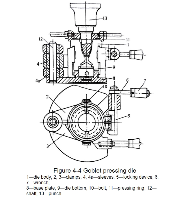
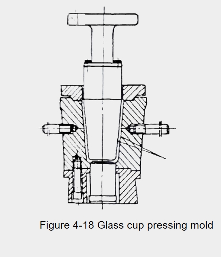
This locking device does not need to be pulled out of the hook ring, because wrench 6 with handle 7 can also be used to open and close the mold. With a fixed base plate 8 with a locking part, the mold can be guaranteed to be symmetrical on the press table, and it is also the base for the mold bottom 9. The die body is fixed in the clamp with two bolts 10. The tail of the bolt has a non-threaded part that extends into the die body so that the die body can automatically align when the two halves of the die are closed. The pressing ring 11 has an inner groove, which can better lock the two halves of the die during pressing and provide for punch 13 to press. Production practice has proved that this structure of the pressing die is also suitable for pressing other products with a height not exceeding 100mm.
Depending on the contour of the product and the molding method, the pouring trough under the storage chamber is either a round trough or a flat trough. When designing the pouring trough, the flow of the glass material in the mold should be considered. In the beginning, the pouring trough can be made smaller. After the mold is tested, the pouring trough can be enlarged according to the results.
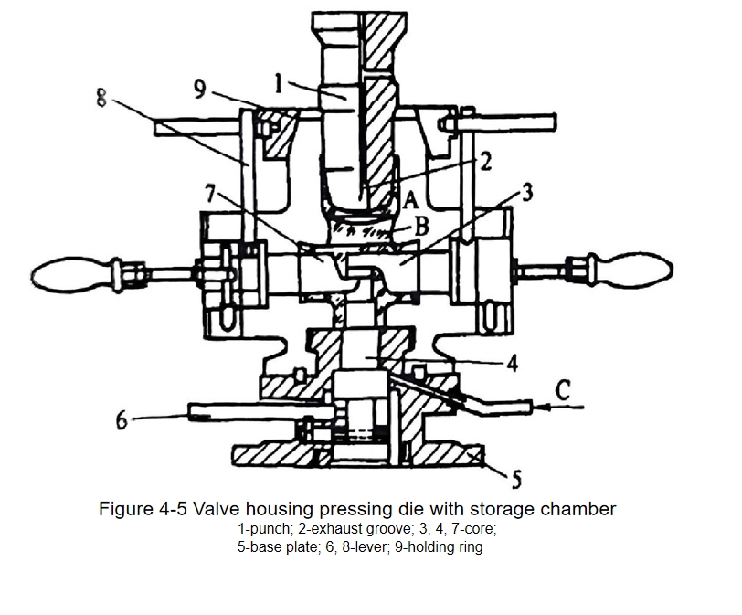
Figure 4-5 shows a valve housing pressing mold with a storage chamber. After the glass material is fed into the storage chamber, punch 1 presses the glass material from chamber A through groove B into the mold cavity. After pressing, lift the punch. To prevent the formation of a vacuum, the punch is provided with an exhaust groove 2. After the mold leaves the working position of the machine, levers 8 and 6 should be turned quickly to pull out cores 7, 3, and 4 from the product, and the passage of cooling air C should be opened so that the cooling air can enter the product and cool the product wall. Remove the ring 9, loosen the tension eccentric device on the mold base plate, and open the two halves of the mold along the guide lugs of the base plate 5.
Bottle making machine mould
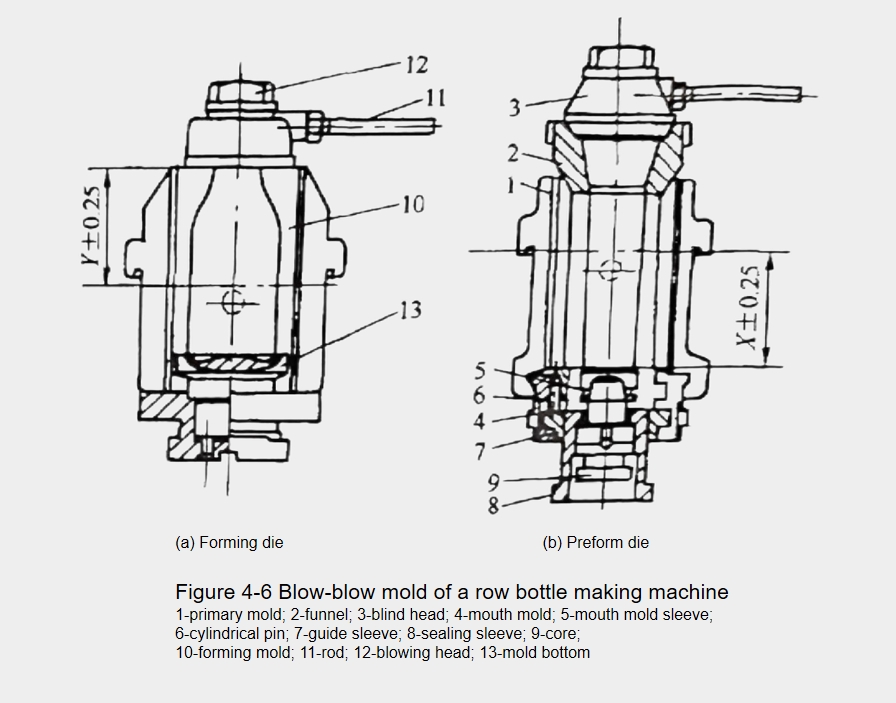
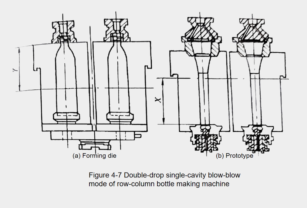
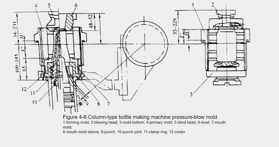
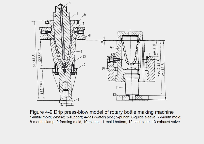
What are the requirements for the performance of the molding machine?
① The molding machine must have the highest productivity under the premise of the best product quality and the best economic effect;
② The molding machine must be easy to operate, convenient to maintain, safe and reliable in operation, and have advanced program control and automation systems;
③ Advanced molding machines, or special equipment that is specially used to mold a certain product to achieve the highest economic and technical indicators; or molding machines that can mold products of various types and specifications and have strong adaptability, one of the two must be selected;
④ The molding machine must be durable, and its maintenance cycle must be compatible with the cold maintenance cycle of the high-age melting furnace;
⑤ The molding machine must have advanced molding technology, reasonable lubrication, and cooling systems, and complete auxiliary facilities.

Complete product samples within 21 day
We have advanced production equipment, the latest tempered glass technology, and strong customized production capabilities. We have a mature logistics team that can transport products to customers in a timely and safe manner.

How do molds and molding machines work together?
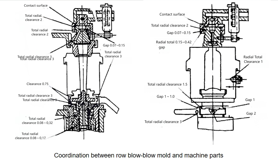
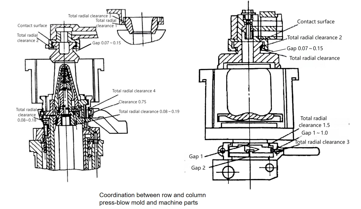
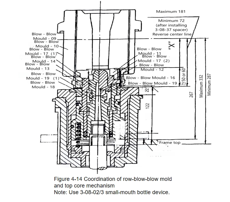
Figure 4-14 shows the assembly relationship between the row-blow mold and the row machine top core mechanism, the matching dimensions, and the mold part
number. The outer diameter (maximum) of the bottle mouth manufactured by the blow-blow method top core mechanism is 50mm. The core stroke is 30mm. The air sealing sleeve stroke is 22mm.
To avoid the “double mouth” problem of bottles and cans, the cylindrical part of the core is required to protrude 0.10-0.15mm into the mouth mold (or mouth mold sleeve). The distance from the inversion center line to the seam line between the mouth mold and the initial mold is called the inversion value “X”. The limit size from the inversion center line to the top surface of the top core mechanism “a maximum of 181mm” refers to the maximum value when the spacer block (3-08-37) is not installed; “minimum 72mm” refers to the minimum value when the spacer block (3-08-37) is installed.
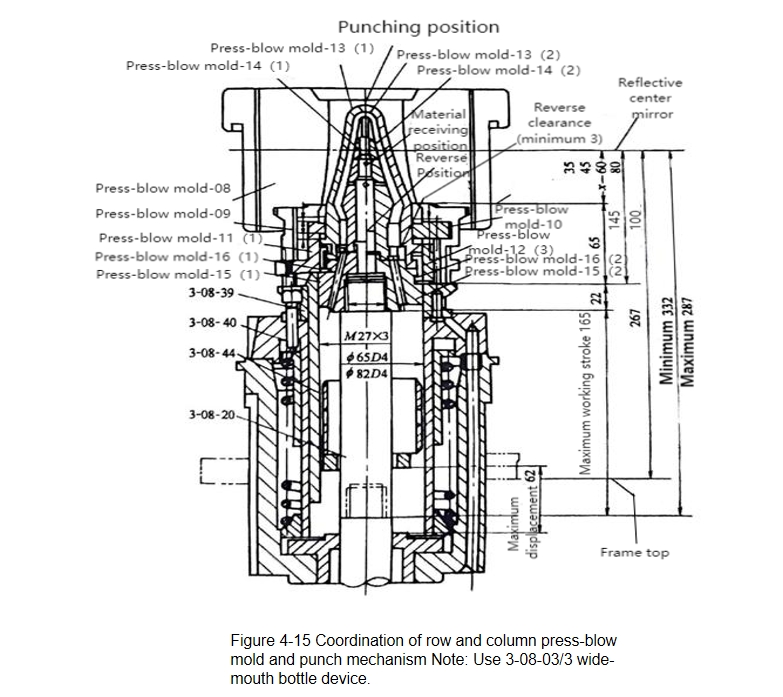
In order to adapt to the deviation of the quality of the glass droplets during production, when designing the punch, it should be considered that its cylindrical part enters the die sleeve 3mm, and ensure that there is a 5mm gap between the punch shoulder and the inner hole shoulder of the die sleeve.
The reversal value “X” can be 35, 45, 60, 80mm, and other four sizes. In order to unify the mold specifications and shorten the mold change time, it is recommended to use X=45mm as much as possible.
The material receiving position can generally be controlled by changing the length of the adjusting screw (3-08-40) and the height of the punch pad tube (3-08-44). The reversal position is determined by the punch pad height, which should ensure that the reversal gap is greater than 3mm.
What are the characteristics of the linear forming machine?
④ The rowing machine can make the formed bottles and cans obtain better glass distribution, especially the various bottles and cans produced by the pressure-blowing method, with uniform wall thickness, which can achieve lightweight glass bottles and cans. Compared with other molding machines, it has higher single-mold production efficiency;
⑤ The main operating mechanism of the row machine does not rotate, the movement is stable, and the operating conditions are good.
The operation process of the row machine blow-blowing method is as follows:
① Loading;
② Air blowing;
③ Backward blowing;
④ Prototype flipping;
⑤ Prototype reheating and extension;
⑥ Positive blowing and initial cooling of bottles and cans;
⑦ Bottle clamping;
⑧ Bottle cooling and transportation.
The operation process of the row machine pressure-blowing method is as follows: ① Loading;
② Pressing the prototype;
③ Prototype flipping.
④ Prototype reheating and extension
⑤ Positive blowing and initial cooling of bottles and cans
⑥ Bottle clamping;
⑦ Bottle cooling and transportation.
What are the design features of blow molds?
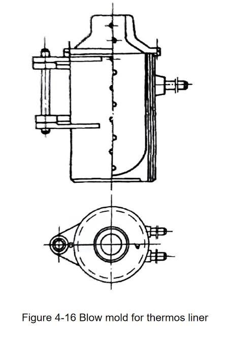
② The cavity consists of the molding and the upper bursting mouth. If the product mouth is small, the neck is thin, and it is particularly long or the shape is complex, to facilitate processing, the molding part can be designed into several parts, and then assembled tightly into one, as shown in Figure 416.
③ Since some blow molds need to be coated with tung oil and sawdust or charcoal powder before use, the inner wall of the cavity does not need to be very smooth. The surface roughness of the inner wall of the cavity is generally Ra6.3μm.
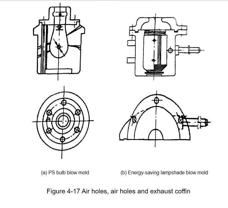
④ The air outlet holes need to be evenly distributed in the mold cavity, and the hole diameter is generally 2-5mm. If it is not blown by rotation, the air outlet hole diameter is φ0.7mm. If the mold is opened and closed, an exhaust groove needs to be opened on the joint surface, as shown in Figure 4-17
⑤ The material requirements of the blow mold are not high. For example, if the iron is loose or there are occasional sand holes below p2mm, it will not affect the quality of the product, but non-rotational blow molding does not allow sand holes. The wall thickness of the mold is generally 14~20mm. The blow mold material can also be made of raw aluminum. If the quantity is small, even a wooden mold can be used.
⑥ The design of the blow mold burst part should consider the appropriate size and convenient burst.
What are the design features of the pressing die?
② The wall thickness of glass products made by the pressing method is generally ≥3mm. The size of the mold body cavity and mold ring should be the actual size of the product plus the shrinkage of the glass. The size of the punch is the size of the cavity minus the wall thickness of the glass product.
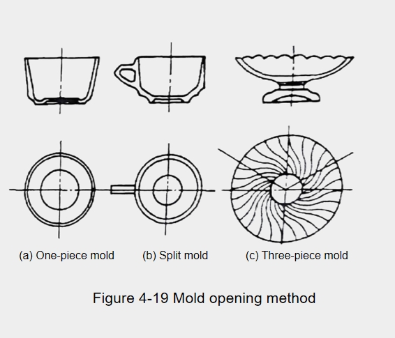
③ The design of the mold body cavity should be based on the shape of the glass product, the complexity of the pattern, and the convenience of demolding the product. It can be designed as an integral mold, a split mold, a three-petal mold, a multi-open mold, etc., as shown in Figure 4-19.
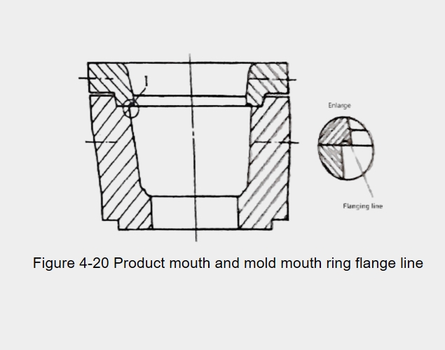
④ The design of the mold ring must have a flanging line, otherwise the glass product will produce burrs and affect the product quality. For example, products such as cathode ray tube glass shells and glass bricks need to be sintered in the subsequent process, so flanging lines are not required, as shown in Figure 4-20.
⑤ The punch and the mold ring must have clearance and interchangeability, and the clearance is generally not less than 0.10mm.
⑥ The surface roughness of the inner wall of the pressing model cavity directly affects the appearance quality of the glass product. Therefore, the surface roughness of the inner cavity of the mold body, mold ring, and punch must be guaranteed to be above Ra0.4μm.
⑦ The wall thickness of the pressing mold is determined by the shape, size, and molding speed of the product. The wall thickness of the mold body should generally be around 30mm. If the wall thickness is too thin, the thermal stability is poor, and the product is prone to cold spots and wrinkles. If the wall is too thick, it is difficult for the mold to reach the required temperature.
⑧ If the temperature of the punch is too high during use, sticky materials will occur. In order to consider cooling, the punch can be hollowed out or cooled with water.
⑨ The pressing mold has high requirements for materials. Casting defects are not allowed in the cavity. The mold cavity of glass products with high requirements needs to be chrome-plated, and the punch is made of stainless steel.
FAQ ——
What are the adjustment measures for scissors print?
② Correct the position of the scissor frame.
③ Replace the scissors in time with the specifications of the sheared products.
④ Increase the drop temperature to improve the scissor mark.
⑤ Increase the amount of atomization lubrication or correct the atomization position.
What are the deformation adjustment measures?
② Improve the removal method and placement method, appropriately extend the cooling time of the product, and delay the demolding time of the product.
What are the inhalation regulation measures?
② Properly extend the holding time of the die.
③ Reduce the die temperature and use air cooling or water cooling for the inner cavity of the die.
④ Reduce the temperature of the cooling medium.
⑤ Properly reduce the glass molding temperature or increase the glass viscosity.
⑥ The inner cavity can be appropriately thinned to accelerate heat dissipation, or air cooling and water cooling can be used. If the effect is still not significant, try to further reduce the temperature of the cooling medium. If the square mold causes air suction at the four corners due to the excessive thickness of the inner cavity, holes can be drilled at the four corners of the inner cavity to reduce the thickness. The diameter and depth of the hole can be determined according to the air suction situation, but it cannot be punched through.
Sometimes a measure is not effective due to the limitations of the process and is difficult to work in time. At this time, several measures can be used at the same time, and small adjustments can be made to the effect. For example: air suction caused by insufficient holding time will increase the probability of product explosion by simply extending the holding time. At this time, measures such as reducing the temperature of the cooling medium and appropriately thinning the mold thickness can also be taken.
What are the cold wrinkle adjustment measures?
② Increase the glass molding temperature or drop temperature.
③ Increase the molding rate per unit time.
What are the methods to adjust the thickness of one side of the product?
② Correct the die so that the centers of the punch, lower die, mouth ring, and die bottom coincide.
What are the adjustment measures for explosive volume?
② Try to change the edges and corners to rounded corners or relax the curvature radius value at the edges and corners to reduce stress concentration, and appropriately increase the insulation measures at the shuttle corners.
③ Reduce the gap between the parting surfaces and heat these parts to increase the temperature at the flash.
④ Shorten the residence time of the glass in the mold after molding, shorten the pressure holding time, and properly insulate and heat the mold and the product.
⑤ Modify the product shape design or mold design, and increase the demoulding slope.
⑥ Improve the cooling speed of the product.
What are the adjustment measures for mold sticking?
② Reduce the drop temperature or extend the cooling time of the product.
③ Improve the cooling conditions of the mold or reduce the temperature of the cooling medium and increase the amount of cooling medium.
④ Improve the mold material
Our other manufacturing capabilities

Glass coating technology
- Heat transfer coefficient (U value) 1.0 – 2.0 W/m²·K
- Visible light transmittance 50% – 80%
See our glass coating technology

Drilling
- Usually between ±0.2-0.5 mm
- The surface roughness after drilling is usually Ra 1.6-3.2 μm
See our drilling technology

Bent glass
- The softening point of the glass is usually between 600-700°C.
- Minimum bending radius: usually 100-150 times the glass thickness